Burkert FLOWave 8098 Quick Start Manual
Flowmeter
Hide thumbs
Also See for FLOWave 8098:
- Operating instructions manual (280 pages) ,
- Quick start manual (68 pages) ,
- Operating instructions manual (241 pages)
Table of Contents
Advertisement
Quick Links
Advertisement
Table of Contents

Subscribe to Our Youtube Channel
Related Manuals for Burkert FLOWave 8098


Summary of Contents for Burkert FLOWave 8098
- Page 1 Type 8098 FLOWave Flowmeter QUICKSTART English...
- Page 2 We reserve the right to make technical changes without notice. © Bürkert SAS, 2015 Quickstart 1511/00_EU-DE 00567159 / Original EN...
-
Page 3: Table Of Contents
Type 8098 About the QuickstArt ................................5 symbols used ..................................5 1.1 Definition of the word "device" ............................5 1.2 Definition of the word "büs" .............................6 1.3 intenDeD use ....................................6 bAsic sAfety informAtion ..............................7 GenerAl informAtion ................................8 manufacturer's address and international contacts ....................8 4.1 Warranty conditions ................................8 4.2 information on the internet ...............................8 4.3 Description .......................................9 5.1 knowing the device ................................9 5.2 understanding the name plates ..........................10 Description of the device status leD ........................12 5.3 technicAl DAtA .....................................13 operating conditions ................................13 6.1 conformity to standards and directives .........................13... - Page 4 user interfAce - DisplAy ..............................34 8.1 safety instructions ................................34 8.2 Description of the user interface ..........................34 8.3 Available login user levels .............................36 8.4 menu structure ..................................39 8.5 how to navigate in the menus and to adjust values ..................40 8.6 Doing the Quick start adjustments when energizing the device for the first time ......44 8.7 changing the type of the output 3 ..........................45 mAintenAnce AnD troubleshootinG ........................46 safety instructions ................................46 9.1 cleaning the device ................................46 9.2 troubleshooting ...................................46 9.3 spAre pArts AnD Accessories ............................47 pAckAGinG, trAnsport ................................47 storAGe ......................................47 DisposAl of the Device .
-
Page 5: About The Quickstart
Fully read the Quickstart. In particular, observe the safety recommendations and intended use. ▶ The quickstart must be read and understood. The full Operating Instructions are on the CD delivered with the product and on the internet at www. burkert.com symbols used danger Warns against an imminent danger. -
Page 6: Definition Of The Word "Büs
Type 8098 AbouttheQuickstart Definition of the word "büs" The word "büS" used in these Operating Instructions refers to the communication bus, developped by Bürkert, based on the CANopen protocol. inTenDeD use use of the device that does not comply with the instructions could present risks to people, nearby installations and the environment. the flowmeter type 8098 is intended to measure the flow rate of clean liquids, non emulsified (homoge- neous liquids) and free of air bubbles and free of gas bubbles and free of solids. ▶ Use the device in compliance with the characteristics and the conditions of commissioning and use specified in the contractual documents and in the Operating Instructions. -
Page 7: Basic Safety Information
Type 8098 Basicsafetyinformation bAsic sAfeTy informATion This safety information does not take into account: • any contingencies or occurrences that may arise during assembly, use and maintenance of the device. • the local safety regulations that the operator must ensure the staff in charge of installation and maintenance observe. -
Page 8: General Information
You may also contact your local Bürkert sales office. The addresses of our international sales offices are available on the internet at: www.burkert.com Warranty conditions The condition governing the legal warranty is the conforming use of the device in observance of the operating conditions specified in this manual. -
Page 9: Description
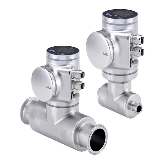
Type 8098 Description DescripTion knowing the device The flowmeter type 8098 is made up of a transmitter type SE98 and a flow sensor type S097. Blind cover, or Display module (type ME31) Device status LED, indicating the status of the device Transmitter housing, including the electronic board(s) Transmitter type... -
Page 10: Understanding The Name Plates
Type 8098 Description The device is delivered with a magnetic key to unlock the display module or the blind cover. See Fig. 2. Fig. 2 : Unlocking magnetic key The device operates on a 4 wire system and needs a 12...35 V DC power supply. The device has three outputs: •... - Page 11 Type 8098 Description SE98 FLOWave Transmitter Supply: 12-35V 5W max. Housing: 304/1.4301 Slot 5: 1AO-1DO-1AO/DO W49MN Made in France 1. Type of the transmitter 2. Power supply and max. power consumption 3. Material the housing is made of 4. Available outputs 5.
-
Page 12: Description Of The Device Status Led
Type 8098 Description Description of the device status leD The LED that indicates the state of the device changes its colour and state based on NAMUR NE 107 standard and usual Bürkert signals. If several states exist simultaneously, the state with the highest priority is displayed. The priority is determined by the severity of the deviation from standard operation (red LED = failure = highest priority). -
Page 13: Technical Data
Type 8098 Technicaldata TechnicAl DATA operating conditions Ambient temperature -10...+70 °C Air humidity < 85%, non condensated Height above see level max. 2000 m Installation category Category II according to UL 61010-1 Pollution degree Degree 2 according to EN 61010-1 Protection class acc. -
Page 14: Fluid Data
Type 8098 Technicaldata fluid data Fluid temperature -20...+110 °C, with clamp process connections. Up to 140 °C for max. 60 minutes for a sterilisation process. Maximum temperature gradient: 10°C/s The maximum fluid temperature can be restricted by the ambient operating temperature. See Fig. 6 Fluid pressure, depending on the pipe diameter •... -
Page 15: Measurement Data
Type 8098 Technicaldata measurement data Refer to the data sheet of type 8098 under www.burkert.com mechanical data Table 2: Materials in contact with the ambient air part material Transmitter housing, sensor housing Stainless steel 304 / 1.4301, outer surface finish Ra < 1.6 µm... - Page 16 Type 8098 Technicaldata Analogue output 1, also output 3 if configured as an • 4...20 mA current; 3.6 mA or 22 mA to indicate an analogue output error • Uncertainty: ±0.04 mA • Resolution: 0.8 µA • Open loop detection through diagnostic software function •...
-
Page 17: Installation And Wiring
Type 8098 Installationandwiring insTAllATion AnD WirinG safety instructions danger Danger due to electrical voltage. ▶ If a 12...35 V DC version is installed either in a wet environment or outdoors, all the electrical voltages must be of max. 35 V DC. ▶ Disconnect the electrical power source for all the conductors and isolate it before carrying out work on the system. -
Page 18: Preparing The Device Before Installation Into The Pipe
Type 8098 Installationandwiring Warning risk of injury if the fluid pressure/temperature dependency is not respected. ▶ Observe the fluid temperature-pressure dependency. Refer to Fig. 6 chap. "6.3 Fluid data". ▶ Observe the Pressure Equipment Directive 97/23/CE. note the device will be damaged if you use a tool to turn the blind cover or the display module. ▶ Do not use a tool to turn the blind cover or the display module. preparing the device before installation into the pipe The device is delivered as described in Fig. - Page 19 Type 8098 Installationandwiring → To change the position of the transmitter as it is described in Fig. 1, chap. 5.1., do the following: For safety reasons and to comply with the UL 61010-1 standard, the blind cover and the display module are locked.
- Page 20 Type 8098 Installationandwiring 6. With an Hex key size 3, loosen the screw that is marked with the arrow and that locks the transmitter to the flow sensor. 7. Hold the flow sensor with one hand and, with the other hand, turn the transmitter by about 20 deg counterclockwise.
- Page 21 Type 8098 Installationandwiring 11. Turn the transmitter in the wanted position. Make sure the cable stays inside the transmitter. 13. Turn the transmitter by about 20 deg counterclockwise. 14. Screw the transmitter clockwise on the flow sensor until the blind cover is perfectly parallel or perpen- dicular to the axis of the pipe.
- Page 22 Type 8098 Installationandwiring 7.2.2 switching positions of the blind cover and the display module The device is delivered with the display module screwed on the top and the blind cover screwed on the housing side. → To switch positions of the display module and the blind cover, do the following: For safety reasons and to comply with the UL 61010-1 standard, the blind cover and the display module are locked.
- Page 23 Type 8098 Installationandwiring 6. Put the magnetic key on the mark related to the blind cover. 7. Turn the blind cover to the unlocked position and remove it. 8. Engage the cable of the display module through the front opening. Connect the cable here 9.
-
Page 24: Recommendations For The Installation Into The Pipe
Type 8098 Installationandwiring recommendations for the installation into the pipe → Protect this device against electromagnetic interference, ultraviolet rays and, when installed outdoors, the effects of the climatic conditions. → To respect the 3A and EHEDG requirements, install the device into a pipe with a minimum angle of 3° against the horizontal. -
Page 25: Installing The Device Into The Pipe
Type 8098 Installationandwiring → Install the device in the pipe in such a way that the upstream and downstream distances are respected according to the design of the pipes, refer to standard ISO 9104:1991 and Fig. 9: flow direction 2 x 90° elbow Control valve joint 40 x DN... - Page 26 Type 8098 Installationandwiring Warning risk of injury due to non-conforming installation. ▶ Fit a circuit breaker or a switch to the electrical installation of the building in which the device is installed. ▶ Install the circuit breaker or the switch in an easily accessible place. ▶ Identify the circuit breaker or the switch as the disconnecting component for the electrical power supply to the device.
- Page 27 Type 8098 Installationandwiring 7.5.2 Assembling and wiring the female m12 connector To assemble and wire the female M12 connector with order code 917116, do the following: → Completely loosen the nut [1]. → Remove the rear part of the connector [2]. →...
- Page 28 Type 8098 Installationandwiring 7.5.5 specifications of the cables for the two m20x1,5 cable glands Table 5: Specifications of the cables for the M20x1.5 cable glands Specification of the cables Recommended value Electromagnetic protection (EMC) shielded Diameter 5 to 14 mm Maximum operating temperature min.
- Page 29 Type 8098 Installationandwiring 7.5.8 opening the front to have access to the terminal block The terminal block can be accessed by opening the front of the transmitter housing, i.e. by removing either the blind cover or the display module. procedure to access the terminal block if the blind cover is on the front of the device 1.
- Page 30 Type 8098 Installationandwiring Push the tab to unlock Carefully pull the display module the cable connector because a cable connects the display module to the transmitter. 5. Push the tab of the cable connector to disconnect the display module from the transmitter. 6.
- Page 31 Type 8098 Installationandwiring 7. If the cable diameter is between 9 and 14 mm, → vertically engage a screwdriver between the two seals, → lift the inner seal and remove it. → Engage the cable through the cable gland. 8. Attach each cable to the functional earth plate. The shield must be in contact with the functional earth plate.
- Page 32 Type 8098 Installationandwiring 7.5.10 connecting the device to a 12...35 V Dc power supply, through the cable glands 1. Disconnect the white wire from terminal no 5. Do not cut the white wire. 2. Insulate the white wire. 3. Connect the power supply as shown in Fig. 16. To connect to the positive 12...35 V DC power supply, through a cable gland To connect to the negative power supply, through a cable...
- Page 33 Type 8098 Installationandwiring 7.5.11 Wiring the output 1 (analogue) and the output 3 configured as an analogue output note risk of short-circuit if the configuration of output 3 is wrong. ▶ Before wiring the output 3 as an analogue output, make sure the output 3 is configured as an analogue out- put in the Parameters menu of the Outputs.
-
Page 34: User Interface - Display
To get detailed information on the display software, refer to the Operating Instructions of the display software type ME31, available on the internet at www.burkert.com The user interface is made up of a display and touch sensitive keys. View 1 of 4... - Page 35 Type 8098 Userinterface-Display 8.2.1 how to use the touch sensitive keys highlighted terms are related to menus or menu items. Table 7: How to use the keys Description Short press: to go back to the parent menu or to the parent view. This key is called BACK in the display messages.
-
Page 36: Available Login User Levels
Type 8098 Userinterface-Display 8.2.2 Description of the display Symbol of the active user level. See chap. „8.3 Available login user levels“. Symbol of the device status Information bar Display parameter Brightness To the DIAGNOSIS Contrast 100% menu, by pressing Screen saver Name of the customized view or of the menu SAW sensor Title of the menu or of... - Page 37 Type 8098 Userinterface-Display Depending on the user level that is active on the device, the following symbols are displayed: Table 8: Possible login user levels symbol Description • Nobody is logged in. No symbol • If the symbol is displayed on a menu item, it is in read-only access. •...
- Page 38 Type 8098 Userinterface-Display 8.3.2 changing the login user level if the adjustment is protected through passwords If the adjustment is protected through passwords, the symbol related to the active user level is displayed in the information bar. Do the following to change the login user level: →...
-
Page 39: Menu Structure
Type 8098 Userinterface-Display menu structure View 1 of 4 CONFIGURATION volume flow 30.1 SAW sensor To navigate through the list of l/min available menu items Configuration view First view, displayed after energizing the device, that can be changed by the user Press to access the dis- played menu item (for example, the item "SAW... -
Page 40: How To Navigate In The Menus And To Adjust Values
Type 8098 Userinterface-Display how to navigate in the menus and to adjust values 8.5.1 Adjusting a percentage or selecting a value in a list Display parameter Brightness Contrast 100% Screen saver Select Confirm Display Save Adjust Brightness Display Contrast Screen saver Save Select Delay... - Page 41 Type 8098 Userinterface-Display 8.5.2 navigating in a wizard and adjusting numbers General settings parameter Alarm limits Quick start Date & Time [1...9] Change language Confirm Parameter Current date/time 1/9 Current date:08/24/15 Current time:08:57:16 Daylight savings Current time zone:+00:London Go back to the previous screen (available at each step of the wizard) Confirm to go to next screens.
- Page 42 Type 8098 Userinterface-Display 8.5.3 entering a name SAW sensor parameter Volume flow Totalizer 1 Totalizer 2 Liquid velocity Confirm SAW sensor volume flow Value name Flow Damping [1...6] Limits Cut-off Confirm Volume flow Confirm selected value name Go to character Go to character Save the name flow...
- Page 43 Type 8098 Userinterface-Display 8.5.4 Activating or deactivating a feature General settings parameter Date & Time [1...9] Change language Passwords Physical units Confirm Parameter passwords Password protection Confirm Passwords password protection Deactivate / Activate Save Fig. 25 : Activating or deactivating a feature English...
-
Page 44: Doing The Quick Start Adjustments When Energizing The Device For The First Time
Type 8098 Userinterface-Display Quick start Doing the adjustments when energizing the device for the first time When the device is energized for the first time, the user is guided to make the following settings, which must be done: • choosing the display language, •... -
Page 45: Changing The Type Of The Output 3
Type 8098 Userinterface-Display changing the type of the output 3 note risk of short-circuit if the configuration of output 3 is wrong. ▶ Before wiring the output 3, make sure the output 3 is correctly configured. The output parameters can be set with the installer user level. By default the output 3 is configured as an analogue output. It can be configured as a digital output. To change the type of the output 3, do the following: →... -
Page 46: Maintenance And Troubleshooting
Type 8098 Maintenanceandtroubleshooting mAinTenAnce AnD TroubleshooTinG safety instructions Danger due to electrical voltage. ▶ Shut down the electrical power source of all the conductors and isolate it before carrying out work on the system. ▶ Observe all applicable accident protection and safety regulations for electrical equipment. risk of injury due to high pressure in the installation. -
Page 47: Spare Parts And Accessories
Type 8098 Sparepartsandaccessories spAre pArTs AnD Accessories attention risk of injury and/or damage caused by the use of unsuitable parts. Incorrect accessories and unsuitable replacement parts may cause injuries and damage the device and the sur- rounding area. ▶ Use only original accessories and original replacement parts from Bürkert. Spare part or accessory Order code Unlocking magnetic key 690309... - Page 48 Type 8098 Sparepartsandaccessories English...
- Page 49 Type 8098 Sparepartsandaccessories English...
- Page 50 Type 8098 Sparepartsandaccessories English...
- Page 52 www.burkert.com...
Need help?
Do you have a question about the FLOWave 8098 and is the answer not in the manual?
Questions and answers