
Related Manuals for Briggs & Stratton 1696423-00


Summary of Contents for Briggs & Stratton 1696423-00
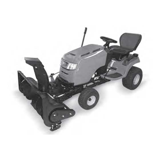
- Page 1 ATTACHMENT OPERATOR’S MANUAL 42” Single-Stage Snowthrower Model No. Description 1696423-00 42” Single Stage Snowthrower Copyright © 2014 Briggs & Stratton Power Products Group, LLC 1756467 Milwaukee, WI USA. All Rights Reserved. Rev: B...
-
Page 3: Table Of Contents
Table of Contents Table of Contents Hardware ..................Hardware Contents ..............Operator Safety ................Operator Safety ................. General ..................Preparation ................Operation .................. Recommended Accessories ............. Decals ..................Features & Controls ..............Control Functions ..............Tractor Controls ................. Assembly ..................Unpacking ................. -
Page 4: Hardware
Hardware Contents - SNOWTHROWER (Not in Hardware Bag /Box) - CHUTE (Not in Hardware Bag /Box) - HITCH ASSEMBLY (Not in Hardware Bag /Box) - LIFT ARM ASSEMBLY (Not in Hardware Bag /Box) - HITCH SUPPORT SHAFT - COTTER PIN - HITCH LATCH PIN G - HAIR PIN - LIFT ROD ASSEMBLY... - Page 5 Hardware Contents J - SAFETY CLIP (Qty. 2) K - SPRING L - TURNBUCKLE - AXLE CLAMP - SWITCH - UPPER WIRE HARNESS - CLIPS (Qty. 4) - EXTENSION WIRE HARNESS - 26” - REFLECTORS (Qty. 2)
-
Page 6: Operator Safety
Operator Safety This snowthrower is capable of amputating hands and feet and throwing objects. Failure to observe the following safety instructions could result in serious injury. Read these safety rules, and the safety rules in your tractor Operator’s Manual, and follow them closely. Failure to obey these rules could result in loss of control of vehicle, severe personal injury to yourself, or damage to property or equipment. -
Page 7: Recommended Accessories
Operator Safety Recommended Accessories WARNING Tire chains are recommended when installing this Perform the Safety System Interlock test found in your attachment to your unit. tractor Operator’s Manual. If tractor does not pass the Safety Decals test, do not operate the tractor. See your authorized dealer. -
Page 8: Features & Controls
Features and Controls Control Functions Tractor Controls The information below briefly describes the function of Before you begin operating the tractor and attachment, individual controls. Operating the tractor and attachment make certain you have: requires the combined use of these controls and additional •... -
Page 9: Assembly
Assembly Hardware / Parts Identification Chute Assembly 1. Remove gear cover (a, Figure 2) from the snowthrower Lower case letters identify pre-assembled and / or pre- assembly (A) by removing hex screw (b) and tilting the existing hardware / parts. gear cover to disengage tab on opposite side of box. -
Page 10: Install Hitch Assembly
Assembly Install Hitch Assembly 4. Rotate chute 180 degrees to front. Chute (B, Figure 4) opening should be facing front / center of machine. 1. Remove the mower deck. Refer to Tractor Operator Manual. 2. Turn the front wheels fully to the left. 3. - Page 11 Assembly 4. On underside of tractor frame, locate 11/16” holes 6. Lift front of the hitch assembly (C, Figure 8) up to tractor approximately 14” forward from rear tire. Insert hitch hook-hitch (c). support shaft (D, Figure 7). Secure with the cotter pin 7.
-
Page 12: Attach Snowthrower To Tractor
Assembly Attach Snowthrower to Tractor 5. Rotate the belt tension lever (e, Figure 11) upwards and towards the back of the tractor into the locked position 1. Position snowthrower assembly in front of tractor. (f). 2. Remove both saftey clips and mounting pins from the snowthrower. - Page 13 Assembly 2. Attach lift arm assembly (H, Figure 13) to the tractor 5. Assemble lift assist parts. Attach spring (K, Figure 15) frame using the four hex bolts (b) and nuts from the to turnbuckle (L) and axle clamp (M). previous step.
-
Page 14: Attach Chute Motor Wiring Harness (Non-Electric Deck Lift Models)
Assembly Attach Chute Motor Wiring Harness 4. Locate the tractor power leads (Figure 21), red with yellow stripe (b) and black (c), at the base of steering (Non-Electric Deck Lift Models) column. Connect these leads, color to color, to the NOTE: Open hood on tractor for installing the wire harness. -
Page 15: Attach Chute Motor Wiring Harness (Electric Deck Lift Models)
Assembly 7. Secure wiring harness in place with clips (P, Figure 23) 2. Plug white female connector end of 26” extension wire to the frame rails. harness (R, Figure 25) into existing tractor wire harness. NOTE: Wire harness slack should be secured and not interfere with moving parts. -
Page 16: Install Reflectors
Assembly Install Reflectors 4. Connect chute rotation wire harness (c, Figure 27) to the 26” extension wire harness (R). Install the two reflectors (Q, Figure 29) on the rear of the tractor seat deck Figure 27 7. Secure wiring harness in place with clips (P, Figure 28) to the frame rails. -
Page 17: Operation
Operation WARNING WARNING If auger does not start and stop when engaging/ Perform the Safety System Interlock test found in your disengaging electric clutch, see your authorized tractor Operator’s Manual. If tractor does not pass the dealer. Under no circumstances should you attempt to test, do not operate the tractor. -
Page 18: Snow Removal Suggestions
Operation Storage Snow Removal Suggestions Daily Storage • Determine the best snow removal pattern before 1. Run the snowthrower a few minutes after blowing snow beginning. to prevent freeze-up of auger. • Wind direction is an important factor to consider. Rotate 2. -
Page 19: Troubleshooting, Adjustments & Service
Troubleshooting Troubleshooting Chart WARNING While normal care and regular maintenance will extend To avoid serious injury, perform maintenance on the the life of your equipment, prolonged or constant use may tractor or snowthrower only when the engine is stopped eventually require that service be performed to allow it to and the parking brake engaged. -
Page 20: Skid Shoe Adjustment
Troubleshooting Skid Shoe Adjustment Lift Adjustment On smooth surfaces such as concrete or asphalt, the In the fully raised position the attachment should be 4”-5” scraper bar should scrape the surface. On surfaces such as off the ground. gravel, the scraper bar should be set high enough so that it 1. -
Page 21: Maintenance
Maintenance WARNING To avoid serious injury, perform maintenance on the unit only when the engine is stopped and all moving parts have stopped. Always remove the ignition key before beginning maintenance or adjustments to prevent accidental starting of the engine. Maintenance Schedule Care Required Schedule... -
Page 22: Warranty
Warranty BRIGGS & STRATTON PRODUCTS WARRANTY POLICY January 2014 LIMITED WARRANTY Briggs & Stratton warrants that, during the warranty period specified below, it will repair or replace, free of charge, any part that is defective in material or workmanship or both. Transportation charges on product submitted for repair or replacement under this warranty must be borne by purchaser. This warranty is effective for and is subject to the time periods and conditions stated below.
Need help?
Do you have a question about the 1696423-00 and is the answer not in the manual?
Questions and answers