
Subscribe to Our Youtube Channel
Related Manuals for Elba EHS 948 S NK


Summary of Contents for Elba EHS 948 S NK
- Page 1 Instructions for the use - Installation advices BUILT-IN COOKING HOBS EHS 948 S NK EHS 945 SB NK EHS 935 SB NK ELBA QUALITY MADE IN ITALY Made in Italy...
- Page 2 Dear Customer, Thank you for having purchased and given your preference to our product. The safety precautions and recommendations reported below are for your own safety and that of others. They will also provide a means by which to make full use of the features offered by your appliance.
-
Page 3: Important Safety Precautions And Recommendations
IMPORTANT SAFETY PRECAUTIONS AND RECOMMENDATIONS IMPORTANT: This appliance is designed and manufactured solely for the cooking of domestic (household) food and is not suitable for any non domestic application and therefore should not be used in a commercial environment. The appliance guarantee will be void if the appliance is used within a non domestic environment i.e. - Page 4 • Do not use a steam cleaner because the moisture can get into the appliance therefore making it unsafe. • Do not touch the appliance with wet or damp hands (or feet). • Do not use the appliance whilst in bare feet. •...
- Page 5 • WARNING: Unattended cooking on a hob with fat or oil can be dangerous and may result in fire. NEVER try to extinguish a fire with water, but switch off the appliance and then cover flame e.g. with a lid or a fire blanket. •...
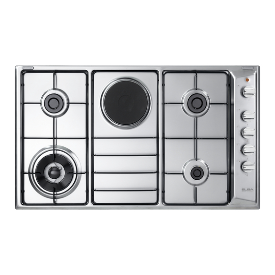
- Page 6 FEATURES AND HOW TO USE THE COOKTOP Model: EHS 935 SB NK Fig. 1.1 Model: EHS 945 SB NK Fig. 1.2 Model: EHS 948 S NK Fig. 1.3...
-
Page 7: Gas Burners
GAS BURNERS Auxiliary (A) 1,00 kW Semirapid (SR) 1,75 kW Triple-ring (TR) 3,50 kW CAST IRON ELECTRICAL HOTPLATE Ø 145 mm, Normal 1000 W CONTROL PANEL DESCRIPTION 10. Burner control knob (A - rear central) 11. Burner control knob (TR - front left) 12. - Page 8 GAS BURNERS Gas flow to the burners is adjusted by turning the knobs (illustrated in fig. 1.4) which control the safety valves. Turning the knob, so that the indicator line points to the symbols printed on the panel, achieves the following functions: –...
-
Page 9: Lighting The Burners
LIGHTING THE BURNERS CHOICE OF THE BURNER ignite burner, following On the control panel, near every knob instructions are to be followed: there is a diagram that indicates which burner is controlled by that knob. Press in the corresponding knob and The suitable burner must be chosen turn counter-clockwise (fig. - Page 10 SPECIAL WOK GRILLE (figs. 1.7a - 1.7b) This special grille for woks should be placed over the pan-rest for the triple ring burner. Warning: • Using woks without this special grille may cause the burner to malfunction. • Do not use the grille for ordinary, flat-bottomed saucepans. IMPORTANT: The special grille for wok pans MUST BE PLACED ONLY over the pan-rest for the triple-ring burner.
- Page 11 ELECTRIC HOTPLATE PROPER USE OF THE ELECTRIC (Model: EHS 948 S NK) HOTPLATE (fig. 1.9) To switch on the hotplate, turn the knob (fig. When the pan comes to the boil, turn the 1.8) onto the desired position; the numbers heat down to the level desired.
- Page 12 ELECTRIC HOTPLATE USAGE TABLE Position TYPE OF COOKING of switch Switched OFF For melting operations (butter, chocolate). To maintain food hot and to heat small quantities of liquid (sauces, eggs). To heat bigger quantities; to whip creams and sauces. (vegetables, fruits, soups). Slow boiling, i.e.: boiled meats, spaghetti, soups, continuations of steam,...
-
Page 13: Cleaning And Maintenance
CLEANING AND MAINTENANCE GLASS LID - optional INSTALLATION OF THE GLASS LID Remove gently the 2 hole-cover plates (T) from the rear edge of the cooking hob, being careful not to chip the enamel (fig. 2.2). Thread the 4 holes (H) with the screws (F) (fig. 2.1). Lubricate the screws with an oil drop to make easy the screwing. - Page 14 SET THE CORRECT BALANCE CLEANING • To clean, it is easy to remove the lid • Close the lid and check the correct by pulling it upwards once it is fully balance; if laid on 45° position it should open. If the hinges ought to slip out, stay hanging.
- Page 15 BATTERY FOR ELECTRIC IGNITION (some models only) In some models the battery is the power supply for the electronic ignition of gas burners. Batteries last on average for about two years (alkaline battery) depending on how often the electronic ignition is used.
- Page 16 FITTING THE BATTERY IGNITION Important notes: SUPPLY • Remove the battery if the cooking hob is not going to be used for a long time. • Remove pan supports and burners from the cooktop. • battery leaks, replace immediately. Avoid touching •...
-
Page 17: General Advice
GENERAL ADVICE • Before you begin cleaning, you must ensure that the appliance is switched off and disconnected from the electrical power supply. • Important: The use of suitable protective clothing/gloves is recommended when handling or cleaning of this appliance. Under no circumstances should any external covers be removed for servicing or •... - Page 18 HOT PLATE (MODELS WITH CAST IRON ELECTRICAL HOTPLATE ONLY) Foods burned on the hot plates must always be cleaned dry. Do not use water to avoid the forming of rust. After its use, pour a bit of oil onto the warm plate and rub with a cloth. BURNERS AND PAN SUPPORTS These parts can be removed and cleaned with appropriate products.
- Page 19 Fig. 2.8 Fig. 2.9 Fig. 2.10 Fig. 2.11 Fig. 2.12...
- Page 20 Advice for the installer IMPORTANT : • The appliance is designed and approved for domestic use only and should not be installed in a commercial, semi commercial or communal environment. Your product will not be guaranteed if installed in any of the above environments and could affect any third party or public liability insurances you may have.
-
Page 21: Installation
INSTALLATION TECHNICAL INFORMATION FOR THE INSTALLER In order to install the cooker top into the kitchen fixture, a hole with the dimensions shown in fig. 3.2 has to be made, bearing in mind the following: • within the unit, between the bottom of the cooktop and the upper surface of a shelf there must be a clearance of at least 30 mm. - Page 22 FASTENING THE INSTALLATION BRACKETS (fig. 3.4) • Each cooker top is provided with an installation kit including brackets and screws for fastening the top to fixture panels from 2 to 4 cm thick. • Turn the cooker top upside down and fasten the brackets “A” to the appropriate socket holes, without tightening the screws “B”...
-
Page 23: Ventilation Requirements
VENTILATION REQUIREMENTS The appliance must be installed in compliance with applicable local regulations concerning ventilation and the evacuation of exhaust gases. Intensive and prolonged use may require extra ventilation, e.g. opening a window, or more efficient ventilation increasing the mechanical suction power if this is fitted. CHOOSING SUITABLE SURROUNDINGS The room where the gas appliance is to be installed must have a natural flow of air so that the gas can burn (in compliance with applicable local regulations). -
Page 24: Gas Section
GAS SECTION GAS INSTALLATION REQUIREMENTS Important ! • Before installation, make sure that the local distribution conditions (gas type and pressure) and the adjustment of this appliance are compatible. The appliance adjustment conditions are given on the plate or the label. •... - Page 25 GAS CONNECTION WITH A RUBBER HOSE Important ! A rubber hose connection shall only be made if permitted by the applicable local regulations. The gas connection fitting (fig. 4.1) is made up of: • the appliance inlet pipe; • the floating nut; •...
- Page 26 Connecting the appliance to LPG If not already fitted, fit the TOWN GAS/NATURAL GAS hose holder on the inlet pipe, making sure that you place the sealing washer between them (as shown in fig. 4.1); then fit the LPG adaptor to the TOWN GAS/NATURAL GAS hose holder, making sure that you place the sealing washer between them (as shown in fig.
- Page 27 After connecting the appliance to the gas supply, make sure that you • check that the connections are correctly sealed using a soapy solution, but never a naked flame. • check whether the injectors are correct for the type of gas being used. If not, follow the instructions under “GAS MAINTENANCE”.
-
Page 28: Testing Operation
When connecting the appliance to the gas supply with rigid pipes or a flexible hose, make sure that • you use rigid pipes or a flexible hose complying with applicable local regulations. The flexible hose shall be of the correct construction for the type of gas being used and of the correct size to maintain the heat output of the appliance. -
Page 29: Lubrication Of The Gas Taps
GAS MAINTENANCE TABLE FOR THE CHOICE OF THE INJECTORS Natural Gas Town Gas G110 Nominal Reduced 28 mbar 20 mbar 8 mbar BURNERS power power [kW] [kW] Ø injector Ø injector Ø injector [1/100 mm] [1/100 mm] [1/100 mm] Auxiliary (A) 1,00 0,30 72 (X) - Page 30 REPLACEMENT OF THE INJECTORS Auxiliary and Select the injectors to be replaced according semi-rapid to the “TABLE FOR THE CHOICE OF THE burners INJECTORS”. nozzle diameters, expressed hundredths of a millimetre, are marked on the body of each injector. If the injectors are not supplied they can be obtained from the “Service Centre”.
-
Page 31: Electrical Section
ELECTRICAL SECTION • If the appliance is to be connected Before effecting any intervention directly to the mains, it must be placed on the electrical parts the appliance with an omnipolar switch with minimum must be disconnected from the opening between the contacts of 3 mm network. -
Page 32: Power Supply Cable
POWER SUPPLY CABLE TYPE “H05V2V2-F” (resistance to temperatures of 90°C) 230 V 50 Hz 3 x 0,75 mm (*) (**) Connection possible with plug and outlet (**) Connection with wall box connection. WARNING: If the power supply cable is damaged, it must be replaced only by an authorised service agent in order to avoid a hazard. - Page 36 The manufacturer cannot be held responsible for possible inaccuracies due to printing or transcription errors in the present booklet. The manufacturer reserves the right to make all modifications to its products deemed necessary for manufacturer commercial reasons at any moment and without prior notice, without jeopardising the essential functional and safety characteristics of the appliances.
Need help?
Do you have a question about the EHS 948 S NK and is the answer not in the manual?
Questions and answers