
Subscribe to Our Youtube Channel
Related Manuals for Elba EHS 311D1 S


Summary of Contents for Elba EHS 311D1 S
- Page 1 Instructions for the use - Installation advices DOMINO COOKING HOBS EHS 311D1 S EHS 321D1 S ELBA QUALITY MADE IN ITALY Made in Italy...
- Page 2 Dear Customer, Thank you for having purchased and given your preference to our product. The safety precautions and recommendations reported below are for your own safety and that of others. They will also provide a means by which to make full use of the features offered by your appliance.
-
Page 3: Important Safety Precautions And Recommendations
IMPORTANT SAFETY PRECAUTIONS AND RECOMMENDATIONS IMPORTANT: This appliance is designed and manufactured solely for the cooking of domestic (household) food and is not suitable for any non domestic application and therefore should not be used in a commercial environment. The appliance guarantee will be void if the appliance is used within a non domestic environment i.e. - Page 4 • CAUTION: this appIiance must only be installed in a permanently ventilated room in compliance with the applicable regulations. • Do not carry out cleaning or maintenance operations on the appliance without having previously disconnected it from the electric power supply. • Do not use a steam cleaner because the moisture can get into the appliance therefore making it unsafe.
- Page 5 Care should be taken to avoid touching heating elements on – the hob. To avoid burns and scalds, young children should be kept – away. • Make sure that electrical cables connecting other appliances in the proximity of the cooktop cannot come into contact with the hob.
- Page 6 ADVICE for the INSTALLER...
- Page 7 IMPORTANT : • The appliance is designed and approved for domestic use only and should not be installed in a commercial, semi commercial or communal environment. Your product will not be guaranteed if installed in any of the above environments and could affect any third party or public liability insurances you may have.
-
Page 8: Installation
INSTALLATION TECHNICAL INFORMATION FOR THE INSTALLER In order to install the cooker top into the kitchen fixture, a hole with the dimensions shown in fig. 1.2 has to be made, bearing in mind the following: • A 30 mm ventilation gap must be provided between the bottom of the appliance and any cabinetry, draw unit or appliance. - Page 9 (figs. 1.3a, 1.3b, 1.3c) FASTENING THE INSTALLATION BRACKETS Each cooktop is provided with an installation kit including brackets and screws for fastening the cooktop to benches from 20 to 40mm thick. The kit includes two “F” type brackets (for the front of the cooktop), two “R” type brackets (for the rear of the cooktop) and four self-threading screws “S”.
-
Page 10: Ventilation Requirements
VENTILATION REQUIREMENTS The appliance must be installed in compliance with applicable local regulations concerning ventilation and the evacuation of exhaust gases. Intensive and prolonged use may require extra ventilation, e.g. opening a window, or more efficient ventilation increasing the mechanical suction power if this is fitted. CHOOSING SUITABLE SURROUNDINGS The room where the gas appliance is to be installed must have a natural flow of air so that the gas can burn (in compliance with applicable local regulations). The flow of air must come directly from one or more openings made in the outside walls with a free area of at least 100 cm (or refer to applicable local regulations). -
Page 11: Gas Section
GAS SECTION GAS INSTALLATION REQUIREMENTS Important ! • Before installation, make sure that the local distribution conditions (gas type and pressure) and the adjustment of this appliance are compatible. The appliance adjustment conditions are given on the plate or the label. •... - Page 12 GAS CONNECTION WITH A RUBBER HOSE (NATURAL GAS OR LPG ONLY) Important ! A rubber hose connection shall only be made if permitted by the applicable local regulations. The gas connection fitting (fig. 2.1) is made up of: • the appliance inlet pipe; •...
- Page 13 Connecting the appliance to LPG If not already fitted, fit the NATURAL GAS hose holder on the inlet pipe, making sure that you place the sealing washer between them (as shown in fig. 2.1); then fit the LPG adaptor to the NATURAL GAS hose holder, making sure that you place the sealing washer between them (as shown in fig.
- Page 14 After connecting the appliance to the gas supply, make sure that you • check that the connections are correctly sealed using a soapy solution, but never a naked flame. • check whether the injectors are correct for the type of gas being used. If not, follow the instructions under “GAS MAINTENANCE”.
- Page 15 When connecting the appliance to the gas supply with rigid pipes or a flexible hose, make sure that • you use rigid pipes or a flexible hose complying with applicable local regulations. The flexible hose shall be of the correct construction for the type of gas being used and of the correct size to maintain the heat output of the appliance. •...
- Page 16 Important! ■ If fitted, remove the hose holder from the terminal fitting of the inlet pipe. ■ The brass conical connector is not already fitted on the appliance (it is supplied in a separate kit); screw that connector to the brass elbow, interposing the sealing washer provided, before starting the connection to the gas supply. Be sure to fit the conical connector as indicated in figure 2.3. Pay special attention to not loosen the elbow and floating nut connection when fitting the brass connector. When connecting the cooktop to the town gas supply, make sure that •...
- Page 17 Gas connection for Town gas only Note: if already fitted, remove the rubber hose holder. Important: fit the brass conical connector (supplied in a separate kit) to the brass elbow. Floating nut Brass elbow Appliance inlet pipe 1/2” G cylindrical (ISO 228-1) male Sealing washer Sealing washer (()
-
Page 18: Testing Operation
TESTING OPERATION (FOR ALL GASES AND ALL TYPES OF CONNECTIONS) The operation of the appliance MUST be tested before leaving. Turn on the gas and light each burner. Check for a well-defined blue flame without any yellow tipping. If any abnormailty is evident, check that the burner cap is located properly and the injector nipple is aligned correctly. - Page 19 REPLACEMENT OF THE INjECTORS Semi-rapid If the injectors are not supplied they can and rapid be obtained from the “Service Centre”. burners Select the injectors to be replaced according to the “TABLE fOR ThE ChOICE Of ThE INjECTORS”. nozzle diameters, expressed hundredths of a millimeter, are marked on the body of each injector.
- Page 20 ADjUSTMENT OF THE EXTERNAL Details of the regulator: GAS REGULATOR (TOWN GAS) MDG ELITRE GVN-01 • For Town Gas (TG) installation, external Model number: EL-12550 (EL-125) gas pressure regulator must be installed. • Gas inlet/outlet connection: ½ inch The TG regulator (provided with the BSP internal thread appliance) has the specifications as per •...
-
Page 21: Electrical Section
ELECTRICAL SECTION – connect the blue wire to the IMPORTANT: The appliance must be terminal marked with the letter “N” installed by a qualified technician or coloured black; according with the current local – connect the brown wire to the regulations and in compliance with terminal marked with the letter “L”... - Page 22 REPLACING THER POWER SUPPLY CABLE WARNING: If the power supply cable is damaged, it must be replaced only by an authorized service agent in order to avoid a hazard. Use the same type of power supply cable. This cable must be connected to the terminal block following the diagram in fig. 3.1. NOTE: The earth conductor must be left about 3 cm longer than the others.
- Page 23 ADVICE for the USERS...
-
Page 24: Control Panel Description
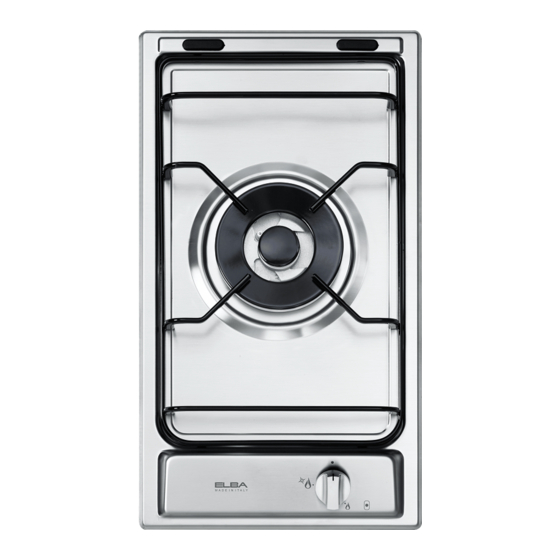
FEATURES Fig. 1.1a Fig. 1.1b Fig. 1.2a Fig. 1.2b COOKING POINTS Semirapid burner (SR) 1,75 kW Rapid burner (R) 3,00 kW Triple ring burner (TR) 3,50 kW CONTROL PANEL DESCRIPTION Rapid burner control knob (2) Semirapid burner control knob (1) Triple-ring burner control knob (3) NOTE: •... -
Page 25: Gas Burners
GAS BURNERS GAS BURNERS NOTE: The knob and symbols may vary. Gas flow to the burners is adjusted by turning the knobs (illustrated in fig. 2.1) which control the safety valves. Turning the knob, so that the indicator line points to the symbols printed on the panel, achieves the following functions: –... - Page 26 LIGHTING GAS BURNERS CHOICE OF THE BURNER FITTED WITH SAFETY VALVE On the control panel, near every knob DEVICE there is a diagram that indicates which burner is controlled by that knob. ignite burner, following The suitable burner must be chosen instructions are to be followed: according to the diameter and the capacity Press in the corresponding knob and...
- Page 27 CORRECT USE OF TRIPLE-RING BURNER- OPTIONAL • To use the WOK you need to place the proper stand (if the the wok pan adapter is not supplied with the appliance, it is available as an accessory at extra cost) in order to avoid any faulty operation of the triple-ring burner (figs.
-
Page 28: Cleaning And Maintenance
CLEANING AND MAINTENANCE GENERAL ADVICE COOKING HOBS WITH • Before you begin cleaning you must GLASS LID (optional) ensure that the hob is switched off. • It is advisable to clean when the appliance is cold and especially when cleaning the enamelled parts. -
Page 29: Control Knob
GAS TAPS CORRECT REPLACEMENT OF THE SEMIRAPID AND RAPID BURNERS Periodic lubrication of the gas taps must be carried out by specialist personnel only. It is very important to check that the burner flame spreader “F” and the cap “C” have In the event of operating faults in the gas been correctly positioned (see figs. - Page 30 Fig. 3.1 Fig. 3.2 Fig. 3.3 Fig. 3.4 Fig. 3.5...
- Page 32 The manufacturer cannot be held responsible for possible inaccuracies due to printing or transcription errors in the present booklet. The manufacturer reserves the right to make all modifications to its products deemed necessary for manufacturer commercial reasons at any moment and without prior notice, without jeopardising the essential functional and safety characteristics of the appliances.
Need help?
Do you have a question about the EHS 311D1 S and is the answer not in the manual?
Questions and answers