Sign In
Upload
Download
Table of Contents
Contents
Add to my manuals
Delete from my manuals
Share
URL of this page:
HTML Link:
Bookmark this page
Add
Manual will be automatically added to "My Manuals"
Print this page
×
Bookmark added
×
Added to my manuals
Manuals
Brands
Elba Manuals
Hob
E95-565 XD
Instructions for the use - installation advices
Elba E95-565 XD Instructions For The Use - Installation Advices
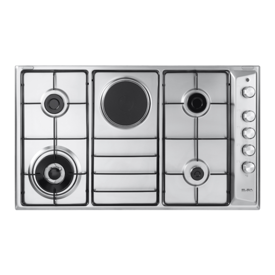
Built-in cooking hobs
Hide thumbs
1
2
3
4
5
6
7
8
9
10
11
12
13
14
15
16
17
18
19
20
21
22
23
24
25
26
27
28
29
30
31
32
33
34
35
36
37
38
39
40
Table Of Contents
41
page
of
41
Go
/
41
Contents
Table of Contents
Bookmarks
Table of Contents
Declaration of Ce Conformity
Important Safety Precautions and Recommendations
Installation
Gas Section
Gas Installation Requirements
Lubrication of the Gas Taps
Electrical Section
Replacing the Power Supply Cable
Features and Technical Data
Control Panel Description
How to Use the Cooktop
Gas Burners
Lighting the Burners
Choice of the Burner
Electric Hotplate/S
Cleaning and Maintenance
General Advice
Advertisement
Quick Links
Download this manual
BUILT-IN COOKING HOBS
GB
Instructions for the use - Installation advices
KEEP IN A SAFE PLACE
Before operating this appliance,
please read these instructions carefully
Table of
Contents
Previous
Page
Next
Page
1
2
3
4
5
Advertisement
Table of Contents
Need help?
Do you have a question about the E95-565 XD and is the answer not in the manual?
Ask a question
Questions and answers
Related Manuals for Elba E95-565 XD
Hob Elba E95-545 XND Instructions For The Use - Installation Advices
Built-in cooking hobs (41 pages)
Hob Elba EH321 Instructions For Use Manual
Domino hobs installation advice (33 pages)
Hob Elba EGH-B8242G(BK) Owner's Manual
Built-in glass hob (10 pages)
Hob Elba E74-200 Instructions For Use - Installation Advice
Elba e74-200; e74-201; e74-300; e74-301; e74-210; e74-211 built-in hobs (60 pages)
Hob Elba ELIO 75-300 Manual
Built-in cooking hobs (33 pages)
Hob Elba EHS 635 SB Instructions For The Use - Installation Advices
Built-in cooking hobs (29 pages)
Hob Elba E30-800 X Instructions For The Use
Domino cooking hobs (40 pages)
Hob Elba EGH-K8943G Owner's Manual
(19 pages)
Hob Elba EHS 935D1 SB Instructions For The Use
Built-in cooking hobs (37 pages)
Hob Elba EHS 945D1 SB Instructions For The Use
Built-in cooking hobs (37 pages)
Hob Elba EGH-E9522G Owner's Manual
(10 pages)
Hob Elba EGH-F9542G Owner's Manual
(10 pages)
Hob Elba EICH-K7072ST Owner's Manual
Induction ceramic hob (25 pages)
Hob Elba ELIO 95-565 CG Instructions For The Use - Installation Advices
Built-in gas on glass cooking hobs (44 pages)
Hob Elba ELIO 65-445 CG Instructions For The Use - Installation Advices
Built-in gas on glass cooking hobs (44 pages)
Hob Elba ELIO 95-545 CG Instructions For The Use - Installation Advices
Built-in gas on glass cooking hobs (44 pages)
This manual is also suitable for:
E95-420 xnd
E90-410 xd
E95-545 xnd
Table of Contents
Print
Rename the bookmark
Delete bookmark?
Delete from my manuals?
Login
Sign In
OR
Sign in with Facebook
Sign in with Google
Upload manual
Upload from disk
Upload from URL


Need help?
Do you have a question about the E95-565 XD and is the answer not in the manual?
Questions and answers