
Subscribe to Our Youtube Channel
Related Manuals for Elba EHS 635 SB


Summary of Contents for Elba EHS 635 SB
- Page 1 Instructions for the use - Installation advices BUILT-IN COOKING HOBS EHS 635 SB ELBA QUALITY MADE IN ITALY Made in Italy...
- Page 2 Dear Customer, Thank you for having purchased and given your preference to our product. The safety precautions and recommendations reported below are for your own safety and that of others. They will also provide a means by which to make full use of the features offered by your appliance.
-
Page 3: Important Safety Precautions And Recommendations
IMPORTANT SAFETY PRECAUTIONS AND RECOMMENDATIONS IMPORTANT: This appliance is designed and manufactured solely for the cooking of domestic (household) food and is not suitable for any non domestic application and therefore should not be used in a commercial environment. The appliance guarantee will be void if the appliance is used within a non domestic environment i.e. - Page 4 • Do not touch the appliance with wet or damp hands (or feet). • Do not use the appliance whilst in bare feet. • If you should decide not to use this appliance any longer (or decide to substitute another model), before disposing of it, it is recommended that it be made inoperative in an appropriate manner in accordance to health and environmental protection regulations, ensuring in particular that all potentially hazardous parts be made...
- Page 5 • WARNING: Danger of fire: do not store items on the cooking surfaces. • WARNING: When correctly installed, your product meets all safety requirements laid down for this type of product category. However special care should be taken around the underneath of the appliance as this area is not designed or intended to be touched and may contain sharp or rough edges, that may cause injury.
-
Page 6: Control Panel Description
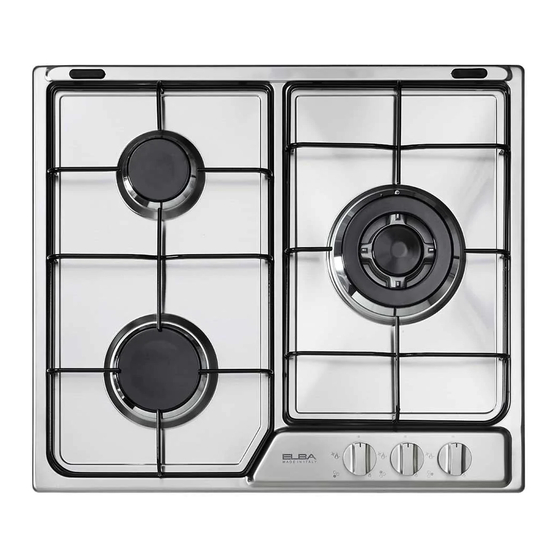
FEATURES AND HOW TO USE THE COOKTOP Fig. 1.1 GAS BURNERS Semirapid (SR) 1,75 kW Rapid (R) 3,00 kW Triple-ring (TR) 3,50 kW CONTROL PANEL DESCRIPTION Triple-ring burner control knob (3) Semirapid burner control knob (1) Rapid burner control knob (2) NOTES: ■... -
Page 7: Gas Burners
GAS BURNERS Gas flow to the burners is adjusted by turning the knobs (illustrated in fig. 1.2) which control the safety valves. Turning the knob, so that the indicator line points to the symbols printed on the panel, achieves the following functions: –... -
Page 8: Lighting The Burners
LIGHTING THE BURNERS CHOICE OF THE BURNER ignite burner, following On the control panel, near every knob instructions are to be followed: there is a diagram that indicates which burner is controlled by that knob. Press in the corresponding knob and The suitable burner must be chosen turn counter-clockwise (fig. - Page 9 SPECIAL WOK GRILLE (figs. 1.5a - 1.5b) This special grille for woks should be placed over the pan-rest for the triple ring burner. Warning: • Using woks without this special grille may cause the burner to malfunction. • Do not use the grille for ordinary, flat-bottomed saucepans. IMPORTANT: The special grille for wok pans MUST BE PLACED ONLY over the pan-rest for the triple-ring burner.
-
Page 10: Cleaning And Maintenance
CLEANING AND MAINTENANCE GENERAL ADVICE COOKING HOBS WITH • Before you begin cleaning, you must GLASS LID (optional) ensure that the appliance is switched off and disconnected from the electrical power supply. • Important: The use of suitable protective clothing/gloves is recommended when handling or cleaning of this appliance. -
Page 11: Stainless Steel Surfaces
ENAMELLED SURFACES All the enamelled parts must be cleaned with a sponge and soapy water only or other non- abrasive products. Dry preferably with a microfibre or soft cloth. If acid substances such as lemon juice, tomato conserve, vinegar etc. are left on the enamel for a long time they will etch it, making it opaque. - Page 12 Fig. 2.1 Fig. 2.2 Fig. 2.3 Fig. 2.4 Fig. 2.5...
- Page 13 BATTERY FOR ELECTRIC IGNITION In some models the battery is the power supply for the electronic ignition of gas burners. Batteries last on average for about two years (alkaline battery) depending on how often the electronic ignition is used. Fig. 2.6 Fig.
- Page 14 FITTING THE BATTERY IGNITION Important notes: SUPPLY • Remove the battery if the cooking hob is not going to be used for a long time. • Remove pan supports and burners from the cooktop. • battery leaks, replace immediately. Avoid touching •...
- Page 15 ADVICE for the INSTALLER IMPORTANT The appliance should be installed, regulated and adapted to function by a QUALIFIED • INSTALLATION TECHNICIAN. • Failure to comply with this condition will render the guarantee invalid. • The appliance must be installed in compliance with the regulations in force in your country and in observation of the manufacturer’s instructions.
-
Page 16: Installation
INSTALLATION TECHNICAL INFORMATION FOR THE INSTALLER In order to install the cooker top into the kitchen fixture, a hole with the dimensions shown in fig. 3.2 has to be made, bearing in mind the following: • within the unit, between the bottom of the cooktop and the upper surface of a shelf there must be a clearance of at least 30 •... - Page 17 INSTALLATION IN KITCHEN Fig. 3.3 CABINET WITH DOOR (fig. 3.3) It is recommended that a 30mm clearance be left between to base of the cooktop and the separator. The separator shall be heat resistant, made Clearance of low thermal conductivity material and shall be removable with the use of a tool for Door installation and service.
-
Page 18: Ventilation Requirements
VENTILATION REQUIREMENTS The appliance must be installed in compliance with applicable local regulations concerning ventilation and the evacuation of exhaust gases. Intensive and prolonged use may require extra ventilation, e.g. opening a window, or more efficient ventilation increasing the mechanical suction power if this is fitted. CHOOSING SUITABLE SURROUNDINGS The room where the gas appliance is to be installed must have a natural flow of air so that the gas can burn (in compliance with applicable local regulations). -
Page 19: Gas Section
GAS SECTION GAS INSTALLATION REQUIREMENTS Important ! • Before installation, make sure that the local distribution conditions (gas type and pressure) and the adjustment of this appliance are compatible. The appliance adjustment conditions are given on the plate or the label. •... - Page 20 GAS CONNECTION WITH A RUBBER HOSE Important ! A rubber hose connection shall only be made if permitted by the applicable local regulations. The gas connection fitting (fig. 4.1) is made up of: • the appliance inlet pipe; • the floating nut; •...
- Page 21 Connecting the appliance to LPG If not already fitted, fit the TOWN GAS/NATURAL GAS hose holder on the inlet pipe, making sure that you place the sealing washer between them (as shown in fig. 4.1); then fit the LPG adaptor to the TOWN GAS/NATURAL GAS hose holder, making sure that you place the sealing washer between them (as shown in fig.
- Page 22 After connecting the appliance to the gas supply, make sure that you • check that the connections are correctly sealed using a soapy solution, but never a naked flame. • check whether the injectors are correct for the type of gas being used. If not, follow the instructions under “GAS MAINTENANCE”.
-
Page 23: Testing Operation
When connecting the appliance to the gas supply with rigid pipes or a flexible hose, make sure that • you use rigid pipes or a flexible hose complying with applicable local regulations. The flexible hose shall be of the correct construction for the type of gas being used and of the correct size to maintain the heat output of the appliance. •... -
Page 24: Lubrication Of The Gas Taps
GAS MAINTENANCE TABLE FOR THE CHOICE OF THE INJECTORS Natural Gas Town Gas G110 Nominal Reduced 28 mbar 20 mbar 8 mbar BURNERS power power [kW] [kW] Ø injector Ø injector Ø injector [1/100 mm] [1/100 mm] [1/100 mm] Semi-rapid (SR) 1,75 0,45 97 (Z) - Page 25 REPLACEMENT OF THE INJECTORS Semi-rapid Select the injectors to be replaced according and rapid to the “TABLE FOR THE CHOICE OF THE burners INJECTORS”. nozzle diameters, expressed hundredths of a millimetre, are marked on the body of each injector. If the injectors are not supplied they can be obtained from the “Service Centre”.
- Page 28 The manufacturer cannot be held responsible for possible inaccuracies due to printing or transcription errors in the present booklet. The manufacturer reserves the right to make all modifications to its products deemed necessary for manufacturer commercial reasons at any moment and without prior notice, without jeopardising the essential functional and safety characteristics of the appliances.
Need help?
Do you have a question about the EHS 635 SB and is the answer not in the manual?
Questions and answers