Table of Contents
Advertisement
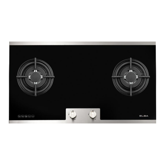
BUILT-IN GLASS HOB
MODEL: EGH-B9230G(BK)
EGH-B9330G(BK)
Owner's Manual
Please read this manual carefully before
operating your set.
Retain it for future reference.
Record model number and serial number
of the set.
See the label attached on the set and
quote this information to your dealer when
you require service.
For The Warranty Terms & Conditions, Please Refer To Warranty Certificate
Advertisement
Table of Contents

Related Manuals for Elba EGH-B9230G


Summary of Contents for Elba EGH-B9230G
- Page 1 BUILT-IN GLASS HOB MODEL: EGH-B9230G(BK) EGH-B9330G(BK) Owner’s Manual Please read this manual carefully before operating your set. Retain it for future reference. Record model number and serial number of the set. See the label attached on the set and quote this information to your dealer when you require service.
-
Page 2: For Your Safety
These instructions have been drawn up for your safety and that of others. You are therefore requested to read them carefully before installing and using the appliance. Keep this instruction manual for future reference as necessary. If the appliance is sold or moved, make sure that the manual is handed over to the new user. -
Page 3: For The User For Your Safety
CHILDREN’S SAFETY This appliance must only be used by adults. Make sure that children do not touch the controls or play with the appliance. The exposed parts of this appliance heat up during cooking and remain hot for some time even after it is switched off. Keep children well away until the appliance has cooled down. -
Page 4: Table Of Contents
Contents For the User For your safety………………………………………………………………… 2 Description of the hob………………………………………………………… Instructions for use …………………………………………………………… 4 Cleaning and maintenance……………………………………………………… 6 For The Installation Technician Technical data………………………………………………………………… Instructions for the installation technician…………………………………… Electrical connection…………………………………………………………… 11 Adapting to the different types of gas………………………………………… 12 Building into fitted kitchen units………………………………………………... -
Page 5: Description Of The Hob
DESCRIPTION OF THE HOB INSTRUCTIONS FOR USE The symbols on the control knobs mean the following: ● no gas flow maximum gas flow Minimum gas flow All operating positions must be set between the maximum and minimum flow settings, and never between the maximum setting and the closed position. -
Page 6: Lighting The Burners
LIGHTING THE BURNERS To obtain a flame more easily, light the burner before placing a cooking utensil on the pan stand To light a burner, proceed as follow: for Version with lighting integrated in the control knob push the knob of the burner fully down and turn it anticlockwise to the “maximum flow”... -
Page 7: Cleaning And Maintenance
CLEANING AND MAINTENANCE Before each operation, disconnect the appliance from the electrical mains and allow it to cool down. GENERAL CLEANING Wash enameled parts with lukewarm water and detergent: do not use abrasive products which might damage them. Wash the flame caps and burner caps often with boiling water and detergent, taking care to remove all deposits The hob pan stands can also be washed in a dishwasher For stubborn dirt, use ordinary non-abrasive detergents or specific commercial... -
Page 8: Warranty Conditions
ROUTINE MAINTENANCE Have the condition and efficiency of the gas pipe and the pressure regulator (if installed) checked periodically. If anomalies are found, do not repairs but have the faulty part replaced. To ensure good performance and safety, the gas regulator taps must be greased periodically. -
Page 9: Technical Data
TECHNICAL DATA Dimensions in mm: Installation opening L x P 1、 550 x 470 2、 550 x 470 3、 750 x 470 OUTPUT OUTPUT 20mbar 28-30mbar 50mbar BURNER Nozzle Nozzle Nozzle TYPE Cons Cons Cons Making Making Making Small Auxiliary 1.00 0.35 0.72... -
Page 10: Discharge Of Flue Gases
INSTALLATION PREMISES For proper operation of a gas appliance, the air necessary for the combustion of the gas must be able to flow into the room naturally. The air must flow into the room directly through openings in the outside walls. These openings must have an unobstructed cross-section not less than 2m /hfor each kw of power (see total power in kw on the appliance nameplate). - Page 11 CONNECTION TO THE GAS SUPPLY The gas Connection must be made in accordance with the local standards. When installing, fit a safety tap at the end of the pipeline. The appliance leaves the factory tested and set for the type of gas indicated on the plate inside the bottom guard, close to the gas connection pipe.
-
Page 12: Electrical Connection
ELECTRICAL CONNECTION The appliance is profited to operate with a power supply voltage of 230Vsingle-phase. The connection must be made in accordance with the regulations and laws in force. Before making the connection, make sure that: 1) the safety circuit-breaker and the electrical system are able to withstand the load of the appliance(see nameplate). -
Page 13: Adapting To The Different Types Of Gas
ADAPTING TO THE DIFFERENT TYPES OF GAS Changing the nozzles Remove the pan standee. 2) Remove the burner caps and flame caps from the burners. 3) Use a size 7 socket wrench to unscrew and remove the nozzles, replacing them with those corresponding to the type of gas to be used (see the table ). -
Page 14: Building Into Fitted Kitchen Units
BUILDING INTO FITTED KITCHEN UNITS These hobs are designed for installation in fitted kitchen units up to 600mm deep with suitable characteristics. Any cabinet side panels taller than the height of the hob itself must be at least 150mm away from the opening into which the hob is inserted. The dimensions of the hob and the installation opening are shown in the illustration. -
Page 15: Installation Options
INSTALLATION OPTIONS On base cabinet with door When constructing the cabinet, suitable precautions must be taken to prevent contact with the casing of the hob, which becomes very during operation. recommended method for overcoming this problem is illustrated in fig.1 The panel underneath the hob must be easily removable to allow the hob to be locked in position and released in case of servicing work On base cabinet with oven... - Page 16 MAIN SPECIFICATION Gas Source : LPG Rated Gas Pressure: 2,800 (Pa) Burner Rating : 3.8kW (Left), 3.8kW (Right), 1.75kW (Middle)* * Only applicable to 3-burner model Built-in Dimension(mm): 750(W) x 470(D) Product Dimension(mm): 860(W) x 510(D)
Need help?
Do you have a question about the EGH-B9230G and is the answer not in the manual?
Questions and answers