
Related Manuals for Elba E74-200


Summary of Contents for Elba E74-200
- Page 1 Built-in hobs Tables encastrables Instructions for the use - Installation advices Mode d’emploi - Conseils pour l’installateur...
- Page 2 ENGLISH Instructions for the use - Installation advices Page The manufacturer cannot be held responsible for possible inaccuracies due to printing or transcription errors in the present booklet. The manufacturer reserves the right to make all modifications to its products deemed necessary for manufacture or commercial reasons at any moment and without prior notice, without jeopardising the essential functional and safety characteristics of the appliances.
-
Page 3: Instructions For The Use
ENGLISH Instructions for the use Dear Customer, Thank you for having purchased and given your preference to our product. The safety precautions and recommendations given below are for your own safety and for others’. This manual will also provide the necessary information to make full use of the features offered by your appliance. -
Page 4: Tips For The User
IMPORT NT PREC UTIONS ND RECOMMEND TIONS After having unpacked the appliance, check to ensure that it is not damaged. If you have any doubts, do not use it and consult your supplier or a professionally qualified technician. Packing elements (i.e. plastic bags, polystyrene foam, nails, packing straps, etc.) should not be left around within easy reach of children, as these may cause serious injuries. - Page 5 4. Burner 1 (SR) control knob NOTE: The model E74-200 .. has a safety valve system fitted. The flow of gas will be stopped if and when the flame should accidentally go out. All the appliances are fitted with an automatic ignition switch incorporated into the knob.
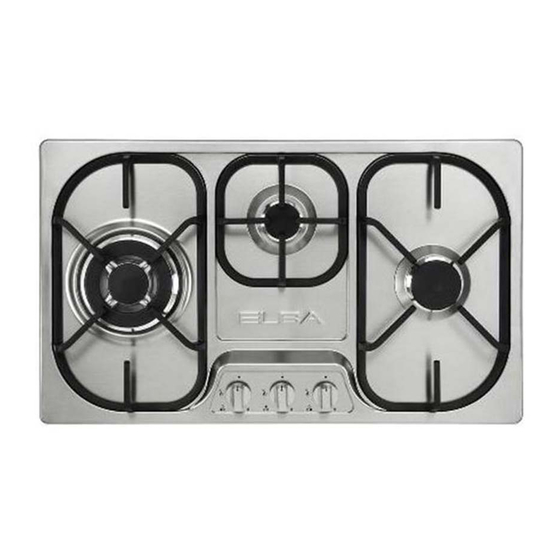
- Page 6 E74-300 .. mod. with safety valve E74-301 .. mod. without safety valve Fig. 1.2 “3 G S” COOKING HOB (Fig. 1.2) COOKING SPOTS 1. Semirapid burner (SR) - 1,75 kW 2. Auxiliary burner (A) - 1,00 kW 3. Triple ring burner (TR) - 3,50 kW CONTROL P NEL DESCRIPTION 4.
- Page 7 E74-210 .. mod. with safety valve E74-211 .. mod. without safety valve Fig. 1.3 “2 G S + 1 ELECTRIC PL TE” COOKING HOB (Fig. 1.3) COOKING SPOTS 1. Semirapid burner (SR) - 1,75 kW 2. Rapid electric plate Ø 145 - 1500 W 3.
- Page 8 G S BURNERS G S BURNERS Models without safety cut-off valves The gas flow to the burners is achieved by turning the knob (illustrated in figs. 2.1a - 2.1b) which controls the safety tap. By turning the knob so that the indicator line points at the symbols printed on the panel we obtain the following settings: full circle...
- Page 9 LIGHTING G S BURNERS LIGHTING G S BURNERS Models with safety valve device Models without safety valve device In order to light the burner, you must: To light one of the gas burners, push in and turn the relative knob to the maxi- 1 –...
-
Page 10: Choice Of Burner
CHOICE OF BURNER DIAMETERS OF PANS WHICH MAY BE USED (fig. 2.3) ON THE HOB The symbols printed on the panel beside the knobs indicate the correspondence BURNERS MINIMUM MAX. between the knob and the burner. Auxiliary 12 cm 14 cm The most suitable burner is to be chosen Semirapid 16 cm... - Page 11 SPECI L WOK GRILLE (figs. 2.4, 2.5) This special grille for woks should be placed over the pan-rest for the triple ring burner. Warning: Using woks without this special grille may cause the burner to malfunction. Do not use the grille for ordinary, flat-bottomed saucepans. IMPORTANT: The special grille for wok pans (figs.
- Page 12 ELECTRIC PL TES R PID HOTPL TE (red dot) PROPER USE OF THE ELEC- TRIC HOTPL TE (fig. 3.2) The characteristics of this hotplate, which is also equipped with a thermo- While using the electric hotplate, you static cut-off device, make it possible to: must: –...
- Page 13 ELECTRIC HOTPL TE US GE Hob controlled by 7-position T BLE 0 - 6 switch Position Type of cooking of switch Switched OFF For melting operations (butter or chocolate) To keep foods warm or heat small quantities of water. To heat greater quantities of water and to whip creams and sauces.
- Page 14 CLE NING ND M INTEN NCE ST INLESS STEEL ELEMENTS GENER L DVICE Stainless steel parts must be rinsed Before you begin cleaning you with water and dried with a soft and must ensure that the hob is clean cloth. switched off.
- Page 15 G S T PS In the event of operating faults in the gas taps, call the Service Department BURNERS ND GRIDS These parts can be removed and cleaned with appropriate products. After cleaning, the burners and their flame spreaders must be well dried and correctly replaced.
- Page 16 CORRECT REPL CEMENT OF THE BURNERS It is very important to check that the burner flame spreader F and the cap C have been correctly positioned (see figs. 4.1 and 4.2). Failure to do so can cause serious problems. In appliances with electric ignition, check that the electrode S (fig. 4.1) is always clean to ensure trouble-free sparking.
-
Page 17: Installation Advice
Installation advice IMPORT NT The appliance should be installed, regulated and adapted to function by a QUALI- FIED INSTALLATION TECHNICIAN. Failure to comply with this condition will render the guarantee invalid. The appliance must be installed in compliance with regulations in force and following the manufacturer's instructions. - Page 18 INST LL TION TECHNIC L INFORM TION FOR THE INST LLER Before installing the hob, remove the protective film. This hob may be built into a worktop of 30 to 40 mm thick and 600 mm deep. In order to install the hob into the kitchen cabinet, an aperture with the dimensions shown in fig.
- Page 19 CUPBO RD DOORS (fig. 5.3) Fig. 5.3 It is recommended that a 30 mm clear- ance be left between the hob and the partition surface underneath. Clearance Cupboard door Space for connections F STENING THE COOKTOP (fig. 5.4 - 5.5) Each hob is supplied with a set of tabs and screws to fasten it on units with a worktop 3 to 4 cm deep.
- Page 20 CHOOSING SUIT BLE Installation technicians must comply SURROUNDINGS to current laws in force concerning ventilation and the evacuation of (for gas models) exhaust gases. The room where the gas appliance is to Intensive and prolonged use may be installed must have a natural flow of require extra ventilation, e.g.
- Page 21 G S SECTION G S INST LL TION REQUIREMENTS Important ! Before installation, make sure that the local distribution conditions (gas type and pres- sure) and the adjustment of this appliance are compatible. The appliance adjustment conditions are given on the plate or the label. This appliance must be installed and serviced only by a suitably qualified, registered installer with technical knowledge of both gas installation and electricity.
- Page 22 CONNECTING THE COOKTOP TO THE G S SUPPLY The gas connection fitting (Figs. 6.1-6.2) is made up of: the floating nut; the elbow; the gaskets; the hose holder for Natural gas or LPG - to be used for gas connection with a rubber hose.
- Page 23 Gas connection with a rubber hose Gasket ISO 228-1 (male) Floating nut 1/2” G cylindrical Elbow Appliance ISO 228-1 (male) inlet 1/2” G cylindrical Gasket pipe Hose holder Hose holder for Natural gas only for LPG only Hose clamp (not supplied) Hose clamp (not supplied) Rubber hose...
- Page 24 DDITION L G S CONNECTION REQUIREMENTS When connecting the cooktop to the gas supply with a rubber hose, make sure that: If not already fitted, you fit the Natural gas or LPG hose holder on the inlet pipe, mak- ing sure that you place the sealing washer between them (as shown in Fig. 6.1). If the hose holder is not supplied with the appliance it can be purchased by contacting the After-Sales Service.
- Page 25 D PTING THE PPLI NCE TO FUNCTION WITH DIFFERENT TYPES OF G S If a different gas from that one indicated on the label is used, you need to adapt the cooktop to this new situation. If the injectors are not supplied they can be obtained from the “Service Centre”.
- Page 26 TABLE FOR THE CHOICE OF THE INJECTORS Cat: II 2H 3+ G30/G31 G 20 28-30/37 mbar 20 mbar Nominal Reduced Ø injector Ø injector Power Power BURNERS [1/100 mm] [1/100 mm] [Hs - kW] [Hs - kW] Auxiliary (A) 1,00 0,30 72 (X) Semi-rapid (SR)
- Page 27 REGUL TING THE BURNER LUBRIC TING THE G S T PS MINIMUM SETTING If one of the gas taps becomes hard to turn, dismantle it, thoroughly clean with When switching from one type of gas to petrol and apply special high-tempera- another, the minimum flow rate must be ture grease.
- Page 28 ELECTRIC L SECTION – connect the brown wire to the ter- IMPORTANT: Installation has to be minal marked with the letter L or carried out according to the instruc- coloured red. tions provided by the manufacturer. It is possible to connect the appliance Incorrect installation might cause directly to the mains by means of a harm and damage to people, ani-...
- Page 29 REPL CING THE POWER SUPPLY C BLE The cable must be replaced with a cable of the same type. 220-240 V The electrical cable must be connect- ed to the terminal block following the diagrams of Fig. 7.1. FEEDER SPECI L C BLE Fig.
- Page 31 FR NÇ IS Mode d’emploi Cher Client Vous venez d’acquérir une de nos tables de cuisson et nous vous remercions de votre choix. Celle-ci a été soigneusement conçue, fabriquée et testée pour votre plus grande satisfaction. Pour être à même de l’utiliser dans les meilleures conditions et pour obtenir ce que vous êtes en droit d’en attendre, nous vous conseillons de lire très attentivement cette notice d’utilisation.
- Page 32 PREC UTIONS ET CONSEILS IMPORT NTS Après avoir éliminé l’emballage, vérifier que l’appareil est en bon état. En cas de doute, ne pas l’utiliser et s’adresser au fournisseur le plus proche ou à un technicien qualifié. Les éléments de l’emballage (sacs en plastique, mousse, clous, feuillards, etc.) doi- vent être laissés hors de portée des enfants, car ils constituent une source potentielle de danger.
- Page 33 4. Manette commande du brûleur 1 (SR) REM RQUE: Le modèle E74-200 .. est équipé d’un système de sécurité. La sortie du gaz est bloquée, si la flamme venait à s’éteindre accidentellement. Le modèle est équipé d’allumage électronique incorporé dans les manettes.
- Page 34 E74-300 .. mod. avec système de sécurité E74-301 .. mod. sans système de sécurité Fig. 1.2 T BLE ENC STR BLE “3 FEUX G Z” (Fig. 1.2) DESCRIPTION DES FEUX 1. Brûleur semi-rapide (SR) - 1,75 kW 2. Brûleur auxiliaire (A) - 1,00 kW 3.
- Page 35 E74-210 .. mod. avec système de sécurité E74-211 .. mod. sans système de sécurité Fig. 1.3 T BLE ENC STR BLE “2 FEUX G Z + 1 PL QUE ELECTRIQUE” (Fig. 1.3) DESCRIPTION DES FEUX 1. Brûleur semi-rapide (SR) - 1,75 kW 2.
- Page 36 BRULEURS BRULEURS Modèles sans système de sécurité L’arrivée du gaz dans les brûleurs est commandée par le bouton illustré sur le figs. 2.1a - 2.1b qui commande les robi- nets munis d’une fermeture de sûreté. En faisant coïncider le symbole du bou- ton avec ceux qui se trouvent sur le tableau, on obtient: disque plein...
- Page 37 LLUM GE ELECTRIQUE LLUM GE ELECTRIQUE DES BRULEURS DES BRULEURS Modèles avec système de sécurité Modèles sans système de sécurité Pour allumer un brûleur: Pour allumer l’un des brûleurs, appuyer sur la manette correspondante (fig. 1 – Faire tourner la manette du robinet 2.1a), et la faire tourner jusqu’à...
- Page 38 CHOIX DU BRULEUR DIAMETRE CASSEROLES (fig. 2.3) Les symboles imprimés sur le tableau à BRULEURS MINIMAL MAXIMAL côté du bouton montrent la correspon- Auxiliaire 12 cm 14 cm dance entre bouton et brûleur. Le brûleur approprié doit être choisi Semirapide 16 cm 24 cm selon le diamètre et la capacité...
- Page 39 GRILLE SPECI LE POUR M RMITES “WOK” (figs. 2.4, 2.5) Cette grille spéciale pour marmites “WOK” se pose sur la grille du brûleur à triple couronne. ATTENTION: L’utilisation de marmites "WOK" sans cette grille spéciale peut causer de graves ano- malies au brûleur.
- Page 40 PL QUE ELECTRIQUE PL QUE R PIDE (point rouge) UTILIS TION CORRECTE DE L PL QUE ELECTRIQUE (fig. 3.2) Les caractéristiques de cette plaque dotée d’un limiteur de réchauffement Lorsqu’on utilise la plaque électrique, il permettent: faut: – d’atteindre rapidement la température éviter à...
- Page 41 CONSEILS POUR L’UTILIS TION DES PL QUES ELECTRIQUES Zone de cuisson commandée 0 - 6 par un bouton à 7 positions Position Type de cuisson manette Eteint Pour faire fondre (beurre, chocolat) Pour garder des plats au chaud et faire chauffer de petites quantités de liquides.
- Page 42 NETTOY GE ET ENTRETIEN CONSEILS GENER UX CIER INOXYD BLE Important: avant toute opération Nettoyer avec des produits spéciaux d’entretien, déconnecter l’appareil que l’on trouve dans le commerce. du réseau et attendre qu’il soit Séchez de préférence avec une refroidi. microfibre ou un tissu mou.
- Page 43 ROBINETS DE G Z En cas de mauvais fonctionnement des robinets de gaz, appeler le Service Après- Vente. BRULEURS ET GRILLES Ces pièces peuvent être enlevées et lavées avec des produits appropriés. Après le nettoyage, les brûleurs et leurs répartiteurs de flamme doivent être bien séchés et remis parfaitement à...
- Page 44 MISE EN PL CE CORRECTE DES BRULEURS Il est très important de vérifier la mise en place parfaite du répartiteur de flamme F et du chapeau C sur le brûleur (voir fig. 4.1 et 4.2), car un déplacement hors du siège peut causer de graves anomalies.
-
Page 45: Instructions Pour L'installation
Instructions pour l’installation IMPORT NT L’installation, le réglage et la transformation de la table de cuisson pour l’utilisation d’autres gaz, doivent être effectués par un installateur qualifié. La non observation de cette règle annule la garantie. L’installation gaz et électrique doit être effectuée correctement, en conformité aux prescriptions locales en vigueur et aux instructions du fabricant. - Page 46 INST LL TION INFORM TION TECHNIQUES POUR L'INST LL TEUR Avant d'installer la table de cuisson, retirer la pellicule de protection éventuelle. Cette table de cuisson peut être encastrée dans un plan de travail de 30 à 40 mm d’épaisseur ayant une profondeur de 600 mm. Pour l’encastrement de la table de cuisson dans le meuble, il faut pratiquer une ouvertu- re aux dimensions indiquées sur la figure 5.1, ben se rappelant que: A l’intérieur du meuble entre le fond de la table de cuisson et la partie supérieure d’un...
- Page 47 INST LL TION SUR DES Fig. 5.3 MEUBLES VEC PORTE (fig. 5.3) Il est conseillé de laisser un espace de dépression de 30 mm entre le fond de la table de cuisson et la partie supérieure du meuble sous-jacent. Espace de FIX TION DE L T BLE DE dépression CUISSON...
- Page 48 LOC L D’INST LL TION Une utilisation intensive et prolongée La pièce dans laquelle l’appareil à gaz peut nécessiter une aération supplé- est installé doit avoir un apport d’air mentaire, par exemple l'ouverture naturel, nécessaire à la combustion du d'une fenêtre ou une aération plus gaz (conformément aux normes locales efficace en augmentant la puissance en viguer).
- Page 49 P RTIE G Z CONDITIONS L’EG RD DE L’INST LL TION U G Z Important ! Avant l’installation, s’assurer que le réseau de distribution local (type de gaz et pression) et les caractéristiques de l’appareil sont compatibles. Les caractéris- tiques sont indiquées sur la plaque ou étiquette. Cet appareil doit être installé...
- Page 50 R CCORDEMENT U G Z Le groupe raccordement (Figs. 6.1-6.2) se compose de: écrou; raccord coudé; rondelles d’étancheité; embout-réduction pour Gaz Naturel ou Butane/Propane - à utiliser pour le raccorde- ment au gaz avec un tuyau en caoutchouc. Important! Raccorder au gaz avec un tuyau en caoutchouc seulement si les normes locales en vigueur le permettent.
- Page 51 Raccordement au gaz avec tuyau en caoutchouc Rondelle ISO 228-1 (mâle) Écrou 1/2” G cylindrique Raccord coudé Collecteur ISO 228-1 (mâle) 1/2” G cylindrique Rondelle l’appareil Embout-réduction Embout-réduction pour pour Gaz Naturel Gaz Butane/Propane Collier de serrage (non fourni) Collier de serrage (non fourni) Tuyau en caoutchouc Tuyau en caoutchouc...
- Page 52 CONDITIONES SUPPLEMENT IRES POUR LE R CCORDEMENT U G Z Lors de la connexion au gaz avec un tuyau en caoutchouc assurez-vous que: S’il n’est pas installé dans l’appareil, Vous connectez l’embout-réduction (pour Gaz Naturel ou Butane/Propane) sur le raccord coudé en interposant la rondelle d’étan- cheité...
- Page 53 D PT TION UX DIFFERENTS TYPES DE G Z Au cas où l’on utilise un gaz différent de celui indiqué sur la plaque signalétique, il faut adap- ter la table de cuisson à cette nouvelle fonction. Les injecteurs sont disponibles aprés des Services Après-Vente. Choisir les injecteurs suivant le tableau injecteurs ci-après.
- Page 54 T BLE U DES INJECTEURS Cat: II 2H 3+ G30/G31 G 20 28-30/37 mbar 20 mbar Débit Débit Ø injecteur Ø injecteur BRULEURS nominal réduit [1/100 mm] [1/100 mm] [Hs - kW] [Hs - kW]] Auxiliaire (A) 1,00 0,30 72 (X) Semi-rapide (SR) 1,75 0,45...
- Page 55 REGL GE DU MINIMUM LUBRIFIC TION DES DES BRULEURS ROBINETS DE G Z En passant d’un type de gaz à un autre, Si un robinet de gaz montre une certaine il faut veiller à ce que le débit réduit soit résistance quand on veut le tourner, il correct.
- Page 56 P RTIE ELECTRIQUE – le fil bleu doit être relié à la borne IMPORTANT: L’installation doit être portant la lettre N ou colorée en effectuée suivant les instructions noir; du constructeur. – le fil marron doit être relié à la Une installation erronée peut cau- borne portant la lettre L ou colorée ser des dommages aux personnes,...
- Page 57 REMPL CEMENT DU CÂBLE D’ LIMENT TION Le câble d’alimentation doit être rem- placé par un câble du même type que 220-240 V celui monté sur l’appareil. Le câble électrique doit être relié au bornier suivant le schéma de la fig. 7.1.
- Page 60 Cod. 1103364 - ß3...
Need help?
Do you have a question about the E74-200 and is the answer not in the manual?
Questions and answers