Table of Contents
Advertisement
Quick Links
Advertisement
Table of Contents

Related Manuals for Advantech UNO-410


Summary of Contents for Advantech UNO-410
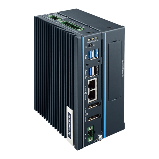
- Page 1 User Manual UNO-410 電腦 Explosion-Proof DIN-Rail Gateway...
- Page 2 No part of this manual may be reproduced, copied, translated, or transmitted in any form or by any means without the prior written permission of Advantech Co., Ltd. The information provided in this manual is intended to be accurate and reliable.
- Page 3 Product Warranty (2 years) Advantech warrants the original purchaser that each of its products will be free from defects in materials and workmanship for two years from the date of purchase. This warranty does not apply to any products that have been repaired or altered by persons other than repair personnel authorized by Advantech, or products that have been subject to misuse, abuse, accident, or improper installation.
- Page 4 This product has passed the CE test for environmental specifications when shielded cables are used for external wiring. We recommend the use of shielded cables. This type of cable is available from Advantech. Please contact your local supplier for ordering information.
- Page 5 IEC 60079-0 and only accessible by the use of a tool. – Transient protection shall be provided that is set at a level not exceeding 140% of the peak rated voltage value at the supply terminal to the equip- ment. UNO-410 User Manual...
- Page 6 This equipment is not suitable for use in locations where children are likely to be present. If the equipment is used in a manner not specified by the Advantech, the protec- tion provided by the equipment may be impaired. UNO-410 User Manual...
- Page 7 UNO-410 is intended to be DIN rail mounted and must be installed in a tool accessible enclosure.” or equivalent. UNO-410 is suitable for use in Class I, Division 2, Groups A, B, C and D or non- hazardous locations only.
- Page 8 ATTENTION: Danger d'explosion si la batterie est mal remplace. Remplacer unique- ment par le meme type ou equivalent recommandé par le fabricant. Jeter les piles usagées selon les instructions du fabricant. 安全指示 請仔細閱讀此安全操作說明。 請妥善保存此用戶手冊供日後參考。 用濕抹布清洗設備前,請確認拔除電源線。請勿使用液體或去污噴霧劑清洗設 備。 對於使用電源線的設備,設備周圍必須有容易接觸到的電源插座。 請勿在潮濕環境中試用設備。 請在安裝前確保設備放置在可靠的平面上,意外摔落可能會導致設備損壞。 設備機殼的開孔適用於空氣對,從而防止設備過熱。請勿覆蓋開孔。 當您連接設備到電源插座前,請確認電源插座的電壓符合要求。 請將電源線佈置在人們不易絆倒的位置,請勿在電源線上覆蓋任何雜物。 請注意設備上所有的警告標示。 UNO-410 User Manual viii...
- Page 9 損壞。 請勿讓任何液體流入通風口,以免引起火灾或短路。 請勿自行打開設備。為了確保您的安全,請透過經認證的工程師來打開設備。 如遇下列情况,請由專業人員維修: 電源線或插頭損壞。 設備內部有液體流入。 設備曾暴露在過度潮濕環境中使用。 設備無法正常工作,或您無法透過用戶手冊來正常工作。 設備摔落或損壞。 設備有明顯外觀損。 請勿將設備放置在超出建議溫度範圍的環境,即不要低於 -40 °C(-40 °F) 或高於 55 °C(131 °F),否則可能會造成設備損壞。 注意:若電池更換不正確,將有爆炸危險。因此,只可以使用製造商推薦的同一 種或者同等型號的電池進行替換。請按照製造商的指示處理舊電池。 根據 IEC 704‐1: 1982 規定,操作員所在位置音量不可高於 70 分貝。 限制區域:請勿將設備安裝於限制區域使用。 免責聲明:請安全訓示符合 IEC 704‐1 要求。研華公司對其內容之準確性不承 擔任何法律責任。 消费者若使用电源适配器供电,则应购买配套使用获得 CCC 认证并满足标准要 求的电源适配器。 UNO-410 User Manual...
- Page 10 UNO-410 User Manual...
-
Page 11: Table Of Contents
Figure 1.1 UNO-410 Dimensions..........5 Chapter Hardware Functionality.......7 Introduction ....................8 Figure 2.1 Diagram of Connector Locations on UNO-410 (Top Side) ................8 Figure 2.2 Diagram of Key Component Locations on UNO-410 (Bottom Side).............. 8 Table 2.1: Key components, Connectors on Board..... 9 External I/O Connector................ - Page 12 Connecting Power................... 21 Storage Installation (optional) ..............22 3.3.1 Installing a 2.5” HDD/SSD (2.5"SSD is default in UNO-410-E1HX) 3.3.2 Installing M.2 SSD ..............27 Din-Rail Installation ................. 28 Wireless Module Installation (Optional) ..........30 iDoor Installation ..................34 Installing lockable kit ................35 3.7.1...
-
Page 13: Chapter 1 Overview
Chapter Overview This chapter overviews specifica- tions for UNO-410. Introduction Safety Precautions Accessories Hardware Specifications Dimensions... -
Page 14: Introduction
The UNO-410 is designed to be safely operated in these locations and are UL listed for hazardous locations with Class I, Division 2, groups A, B, C, D, T4, and ATEX/ IECEx zone 2 certification. -
Page 15: Packing List
1 x M2x4L screw for mPCIe card installation 2 x Lockable kit 1 x Earth-Ground cable 1 x SATA cable (It will be installed with 2.5" SSD inside UNO-410 unit in UNO- 410-E1HX sku) Quick Start Guide Simplified Chinese manual ... -
Page 16: System Hardware
3 x USB 3.2 Gen1, and 1 x USB 2.0 (Type A) 8-ch digital input, 8-ch digital output (Isolation Protection: Isolated DIO 2500Vdc) Displays 2 x DP 1.2, up to 4096x2306@60Hz (Support DP++) Power Connector 1 x 2 Pin (terminal block) UNO-410 User Manual... -
Page 17: Environment
1.4.5 Certifications CE; FCC; CCC; UL 61010-2-201 Certification Class I, Division 2, Groups A, B, C, D ATEX/IECEx Zone 2 Dimensions 70 x 105 x 150 mm (2.8 x 4.1 x 5.9 in) Figure 1.1 UNO-410 Dimensions UNO-410 User Manual... - Page 18 UNO-410 User Manual...
-
Page 19: Chapter 2 Hardware Functionality
Chapter Hardware Functionality This chapter details setup instruc- tions for UNO-410’s hardware functions. It includes connecting peripherals and indicators. Introduction External I/O Connector Internal I/O Connector LED Indicators Reset Buttons Antenna Hole... -
Page 20: Introduction
Introduction The following diagram shows the location of UNO-410’s motherboard’s key compo- nents and internal/external connectors. Figure 2.1 Diagram of Connector Locations on UNO-410 (Top Side) Figure 2.2 Diagram of Key Component Locations on UNO-410 (Bottom Side) UNO-410 User Manual... - Page 21 USB 3.0 Connector 8DI/ 8DO Terminal Connector COM Port Terminal Connector (RS232/422/485) SATA Power Connector SATA1 SATA Signal Connector MINI1 MiniPCIe Connector Internal CN13 Reserved for connector expansion CN15 M.2 B key for 2242/3042/3052 Connector CN12 Memory slot UNO-410 User Manual...
-
Page 22: External I/O Connector
Figure 2.4 Top View of UNO-410 2.2.1 Power Connector UNO-410 comes with a Phoenix connector that carries 10 - 36 external power input, and features reversed wiring protection. Therefore, the system will not accrue damage from reversed polarity of ground lines and power lines. (Please refer to User Manual - Appendix A.1 for pin assignments.) -
Page 23: Usb Connector
2.2.3 USB Connector UNO-410 features 4 x USB ports that comply with USB EHCI, 3 x for Rev. 3.0, 1 x for Rev. 2.0 specifications. The USB connectors support plug-and-play and hot-swap- ping functionality for external devices. Additionally, this can be enabled/disabled in the BIOS menu. -
Page 24: Digital Input And Output (Cn7)
– Logic 1: 0~3 Input voltage (dry contact), configure SW6 to setting 1 – Logic 0: Shorted to GND – Logic 1: Open Isolation protection 2,500 Over-voltage protection 30 Opto-Isolator response 50 μs UNO-410 User Manual... - Page 25 5 mA max/ch (UL testing conditions), the board's current will sink from the external voltage source. The following figure shows how to connect an external output load to the isolated outputs on UNO-410. Figure 2.7 Isolated DO Connection Diagram...
-
Page 26: Internal I/O Connectors And Switches
Internal I/O Connectors and Switches The following figure shows the locations of internal connectors and switches on the UNO-410’s motherboard. Figure 2.8 Locations Internal I/O Connectors/Switches for UNO-410 Table 2.3: Internal Connectors and Jumper Switches Label Function MINI1 MiniPCIe connector CN15 M.2 B key for 2242/3042/3052 connector... -
Page 27: Sata Connector/Sata Power Connector
Configure the UNO-410 to match the needs of your application by setting switches, The following diagram shows switch setting definitions: 2.3.1 SATA Connector/SATA Power Connector There are two required onboard connectors that need to connect with 2.5" SATA SSD/HDD. The location labeled “SATA1” is for SATA connector, and the location labeled “CN9”... -
Page 28: Others
BTR (RTC Battery): Red indicates a low RTC battery. Check the RTC battery. RUN (Programmable): Users can configure the LED indicator’s behavior through GPO signal controls. Green indicates under programming. 2.4.2 Reset Buttons Press the “Reset” button to initiate a hardware reset. UNO-410 User Manual... -
Page 29: Antenna Hole
LTE or wireless functions. Note! Please be aware of the maximum OD value of the antenna hole when selecting an antenna. Figure 2.10 Diagram of Maximum OD Value for Antenna Hole UNO-410 User Manual... - Page 30 UNO-410 User Manual...
-
Page 31: Chapter 3 Initial Setup
Chapter Initial Setup This chapter explains how to Ini- tialize the UNO-410. Chassis Grounding Connecting Power Storage Installation (Optional) Din-Rail Installation Wireless Module Installation (Optional) Expansion Module Installation (Optional) Remote Power/On & Reset Set- ting ... -
Page 32: Chassis Grounding
Chassis Grounding The UNO-410 provides good EMI protection and a stable grounding base. There is an easy-to-connect chassis grounding point. Figure 3.1 Chassis Grounding Connection Diagram Use the Grounding cable (16 AWG) from the accessory bag to connect the chassis ground with the Earth ground. -
Page 33: Connecting Power
This product is intended to be supplied by an approved power adapter or DC power source. This adapter is rated at 10 - 36Vdc, 7.7A max and has a Tmax of 55 °C (131 °F). If you need further assistance or information, please contact Advantech. Note! Please choose the Power Adapter with UL certification in Class I, Divi- sion 2, Groups A, B, C,D T4. -
Page 34: Storage Installation (Optional)
Storage Installation (optional) UNO-410 supports the installation of one 2.5” HDD/SDD and one M.2 2242 SSD. The installation is demonstrated in the following steps. 3.3.1 Installing a 2.5” HDD/SSD (2.5"SSD is default in UNO-410- E1HX) Remove 2 screws from the back cover. - Page 35 Disassemble the 1 stack and 2 stack screws on UNO-410. UNO-410 User Manual...
- Page 36 Detach the HDD bracket from 2 stack. Fix the 2.5” HDD/SSD to the HDD bracket with the 4 x M3x4L screws from the accessory bag. UNO-410 User Manual...
- Page 37 Attach the HDD bracket back to the 2 stack with the provided screws from step 3. UNO-410 User Manual...
- Page 38 Reassemble 1 stack and 2 stack of UNO-410. (1) Plug in SATA cable onto the board of UNO-410 and connect with SSD/HDD. (2) Fix extension kit with 5 x M3x4L screws from the accessory bag. UNO-410 User Manual...
-
Page 39: Installing M.2 Ssd
Return the back cover of UNO-410. 3.3.2 Installing M.2 SSD Remove 2 screws from UNO’s back cover. Disassemble 1st stack and 2nd stack of UNO-410. Remove the provided screws from the board. UNO-410 User Manual... -
Page 40: Din-Rail Installation
Insert the M.2 card on the location: “CN15”. Secure it with the provided screws from Step 3. Din-Rail Installation Install UNO-410 on the rail and secure it to the rail. UNO-410 User Manual... - Page 41 Pull down the “Release Latch” for disassembly using a screwdriver. UNO-410 User Manual...
-
Page 42: Wireless Module Installation (Optional)
Wireless Module Installation (Optional) UNO-410 supports a WiFi iDoor/M.2 3042/M.2 3052 module. Follow the steps below for installation: Remove 2 screws from the back cover of UNO. Disassemble 1 stack and 2 stack of UNO-410. Remove the plug of antenna pre-cut hole(s) on the top panel for antenna instal- lation. - Page 43 (2) Insert the M.2 card to the location: “CN15” and secure it with the provided screws from Step 4-1. Install the SMA connector of *Antenna cable to the Antenna hole. UNO-410 User Manual...
- Page 44 Connect the MHF of Antenna cable with module. Reassembly 1 stack and 2 stack of UNO-410. Assemble the *Antenna on the SMA connector of the Antenna cable. *Wireless Module, Antenna cable, Antenna are optional. Please use the modules that were controlled by the certification and refer to UNO- 410 Data Sheet for more ordering details.
- Page 45 Note! If you need to install M.2 3052 Module, please follow the following steps. Remove the on-board “bracket”. Use the provided screws from Step1 to fix the M.2 3052 module. UNO-410 User Manual...
-
Page 46: Idoor Installation
Installation: (1) Connect the mPCIe connector of iDoor module onto the board of UNO-410. (2) Fix it with the M2x4L screw from the accessory bag. (3) Install and secure the iDoor module with the provided screws from step 2. -
Page 47: Installing Lockable Kit
UNO System to make sure the USB cables have been secured tightly on the system to prevent unintentional disconnection. 3.7.2 Part number UNO-2000-LKAE (with 10 sets inside, UNO-410 has 2 sets as default package). 3.7.3 Lockable kit configuration Lockable screw is used to plug into Lockable screw the hole between USB ports on UNO. -
Page 48: Assembly With The Uno System
3.7.4 Assembly with the UNO System Follow the 4 steps to fix the USB cable with the lockable kit: Find the lockable hole on UNO System near the USB Port. UNO-410 User Manual... -
Page 49: Remote Power & Reset Settings
(SW8) on the motherboard. The default setting is for DI6/DI7 function- ality. If you want to configure UNO-410 for remote control functions, configure SW8- Bit 2 to “on”, then DI6 can be used for remote power settings, and DI7 can be used for remote reset setting. - Page 50 UNO-410 User Manual...
-
Page 51: Appendix A System Settings/Pin Assignments
Appendix System Settings/Pin Assignments... -
Page 52: Power Connector (Cn1)
1000BASE-T: In MDI and in MDI-X configuration, MDI2- MDI[2]+/- corresponds to BI_DC+/- and MDI[3]+/ - MDI3+ corresponds to BI_DD+/-. 100BASE-TX: Unused. MDI3- 10BASE-T: Unused. Left LED Right LED 100 Link 1000 Link Active 10Link Orange Green Green UNO-410 User Manual... -
Page 53: Usb Connector (Cn5,Cn6)
Table A.4: USB 3.0 Connector Pin Assignments Signal Name Description VBUS Power (+5.0V) USB 2.0 differential pair Ground for power return StdA_SSRX- SuperSpeed receiver differential pair StdA_SSRX+ GND_DRIAN Ground for signal return StdA_SSTX- SuperSpeed transmitter differential pair StdA_SSTX+ UNO-410 User Manual... -
Page 54: Display Connector (Cn2,Cn3)
Signal Name ML_Lane 0 (p) ML_Lane 0 (n) ML_Lane 1 (p) ML_Lane 1 (n) ML_Lane 2 (p) ML_Lane2 (2) ML_Lane 3 (p) ML_Lane 3 (n) CONFIG1 CONFIG2 AUX CH (p) AUX CH (n) Hot Plug Return DP_PWR UNO-410 User Manual... -
Page 55: Sata Connector/Sata Power Connector
Table A.6: SATA Connector Pin Assignments Signal Name SATA0_C_TX+ SATA0_C_TX- SATA0_RX- SATA0_RX+ A.5.2 SATA Power Connector (CN9) Table A.7: SATA Power Connector Pin Assignments Signal Name Description +V5SATA Power (+5.0V) Ground for power return Ground for power return Reserved UNO-410 User Manual... -
Page 56: Connector (Cn15)
Mechanical notch B Mechanical notch B Mechanical notch B Mechanical notch B Mechanical notch B Mechanical notch B WAKE_ON_WAN# M2_LTE_W2_DISABLE_N USB_Z_SSRX1- M2_SIM1_RESET USB_Z_SSRX1+ M2_SIM1_CLK M2_SIM1_DATA USB_C_SSTX1- M2_SIM1_PWR USB_C_SSTX1+ M2_SIM2_DET SATA1_RX+ SATA1_RX- SATA1_C_TX- SATA1_C_TX+ M2_SIM1_DET LTE_RST#_P67 +V3.3_M2 +V3.3_M2 +V3.3_M2 UNO-410 User Manual... -
Page 57: Mpcie Connector (Mini1)
Connector (MINI1) Table A.9: mPCIe Connector Pin Assignments Signal Name Signal Name PCIE_WAKE#_3.3 +V3.3_MINI +V1.5 +V3.3 CLK_PCIE_mPCIe1- CLK_PCIE_mPCIe1+ WIFI_DISABLE# MINI_PLTRST# PCIE_mPCIe_RX4- +V3.3_MINI PCIE_mPCIe_RX4+ +V1.5 PCIE_TX2-_Z PCIE_TX2+Z USB_Z_P0- USB_Z_P0+ +V3.3_MINI +V3.3_MINI MPCIE_PWRSEL +V1.5 +V3.3_MINI UNO-410 User Manual... -
Page 58: Com Port Rs232/422/485 Settings
Mode Bit 1,3,6,7,8,9,10 OFF RS422 Bit 1,2,4,5 ON Mode Bit 3,6,7,8,9,10 OFF RS232 Bit 6 ON Mode Bit 1,2,3,4,5,7,8,9,10 OFF RS485 Bit 7,9,10 ON COM2 Mode Bit 1,2,3,4,5,6,8 OFF RS422 Bit 6,7,9,10 ON Mode Bit 1,2,3,4,5,8 OFF UNO-410 User Manual... -
Page 59: Com Port Rs422/485 Termination Resistor Setting
AT/ATX Setting (SW8) SW8 can be used for AT/ATX setting. The default setting is AT mode. See the follow- ing table for switch configuration. SW8 Default Description Instruction AT Mode Bit 1 off (Default) ATX Mode Bit 1 on UNO-410 User Manual... -
Page 60: Board To Board Connector (Reserved For Expansion) (Cn13)
Table A.10: Expansion Board to Board Connector Pin Assignments Signal Name Signal Name eDP_HPD# eDP_TX0+ eDP_TX0- eDP_TX1+ eDP_TX1- eDP_AUX+ eDP_AUX- PLTRST_B2B# PMU_SLP_S3# eDP_VDDEN_1V8 eDP_BKLTEN_1V8 eDP_BKLCTL_1V8 EC_LVDS_BKLT_EN EC_LVDS_BKLT_CTL ouch_EN_1V8 PCIE_WAKE#_3.3 CLK_PCIE_mPCIe0+ CLK_PCIE_mPCIe0- PCIE_TX2+ PCIE_TX2- PCIE_RX2+ PCIE_RX2- USB2_P2+ USB2_P2- PCIE_MINI1_CLKREQ# UNO-410 User Manual... -
Page 61: Tpm 2.0 Bios Setting
A.11 TPM 2.0 BIOS Setting The UNO-410 systems support TPM 2.0 functionality. This can be enabled or dis- abled in the BIOS menu by following the instructions provided below: Power on the UNO-410 system and press “Delete” to enter the BIOS configura- tion menu. - Page 62 Then select the “Security Device Support” item. Choose “enable/disable” to enable or disable the TPM 2.0 function. (The default setting is to enable this function.) UNO-410 User Manual...
-
Page 63: Cpu Turbo Mode Bios Setting
A.12 CPU Turbo Mode BIOS Setting The UNO-410 systems support CPU Turbo mode. This can be enabled or disabled in the BIOS menu by following the instructions : Power on the UNO-410 system and press “Delete” to enter the BIOS configura- tion menu. - Page 64 Then select the “CPU Power Management” item. Choose “enable/disable” to enable or disable the CPU Turbo mode. (The default setting is to enable this function.) UNO-410 User Manual...
- Page 65 UNO-410 User Manual...
- Page 66 No part of this publication may be reproduced in any form or by any means, electronic, photocopying, recording or otherwise, without prior written permis- sion from the publisher. All brand and product names are trademarks or registered trademarks of their respective companies. © Advantech Co., Ltd. 2021...
Need help?
Do you have a question about the UNO-410 and is the answer not in the manual?
Questions and answers