
Subscribe to Our Youtube Channel
Related Manuals for RDZ DA 2001


Summary of Contents for RDZ DA 2001
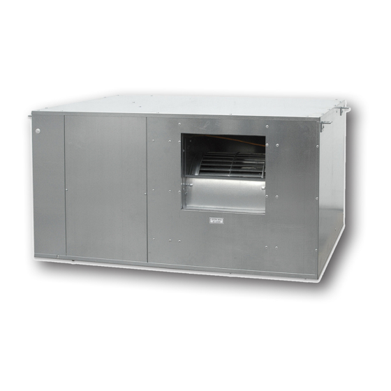
- Page 1 Air Handling Units Unità Trattamento Aria DA 2001 Dehumidifier horizontal ceiling mounted - Commercial Units Terziario - Deumidificatore orizzontale a soffitto INSTALLATION / TECHNICAL MANUAL MANUALE INSTALLAZIONE / TECNICO...
-
Page 3: Avvertenze Generali
Il suo utilizzo è raccomandato, entro i limiti di funzionamento, in ambienti civili e/o del applications and/or commercial ones (e.g. offices). Any other different use MUST be agreed in advance with RDZ technical settore terziario (uffici, ...), per climatizzazione finalizzata department. -
Page 4: Avvertenze Per La Sicurezza
SAFETY WARNINGS | AVVERTENZE PER LA SICUREZZA Read this manual carefully before installing and/or using the Le g g e re co n at te n z i o n e q u e s to l i b re t to p r i m a equipment and keep it in an accessible place. -
Page 5: Smaltimento
DISPOSAL | SMALTIMENTO In accordance with the provisions of the following In base a quanto previsto dalle seguenti direttive European directives 2011/65/EU, 2012/19/EU and europee 2011/65/UE, 2012/19/UE e 2003/108/ 2003/108/EC, regarding reducing the use of CE, relative alla riduzione dell’uso di sostanze hazardous substances in electrical and electronic pericolose nelle apparecchiature elettriche ed equipment, in addition to waste disposal. -
Page 6: Table Of Contents
INDEX | INDICE Description Descrizione GENERAL WARNINGS AVVERTENZE GENERALI SAFETY WARNINGS AVVERTENZE PER LA SICUREZZA DISPOSAL SMALTIMENTO PRELIMINARY OPERATIONS OPERAZIONI PRELIMINARI GENERAL OVERVIEW PANORAMICA GENERALE Description Descrizione Machine Components Componenti Apparecchiatura Package Content Contenuto Imballo Complements Complementi Unit circuit description Descrizione circuiti macchina Internal component description Descrizione componenti interni... -
Page 7: Preliminary Operations
PRELIMINARY OPERATIONS | OPERAZIONI PRELIMINARI TESTING, TRANSPORT AND UNPACAKGING ISPEZIONE, TRASPORTO E DISIMBALLO Upon receipt, check immediately that the packaging is intact: All’atto del ricevimento verificare immediatamente l’integrità the machine has left the factory in perfect working order and any dell’imballo: la macchina ha lasciato la fabbrica in perfetto stato, damage must be notified to the carrier immediately and noted on eventuali danni dovranno essere immediatamente contestati... -
Page 8: General Overview
1 GENERAL OVERVIEW | PANORAMICA GENERALE 1.1 DESCRIPTION | DESCRIZIONE Deumidificatore DA 2001 per impianti di climatizzazione radiante, DA 2001 dehumidifier shall be combined with radiant cooling, and it adatto all’installazione nel terziario, provvede al trattamento dell’aria is suitable for medium-sized commercial applications and medium di locali con media volumetria e discreto livello di affollamento. - Page 9 FLUSSI ARIA - AIR FLOWS Supply Air Recirculation Air Immissione Aria Ricircolo Aria coarse 1” F ½” F ½” F 1” F Hydraulic connection Wiring Box Ø 20 mm Condensation Drain Attacchi idraulici Quadro Elettrico Scarico Condensa Ø 20 mm AIR FILTERS - FILTRI ARIA Classes, Minimum E ciency, Type Of Particulate / Classi, E cienza Minima, Tipo Di Particolato e(PM10) min ≥...
-
Page 10: Contenuto Imballo
SF-P Condensate drain kit with casing, designed for wall installation. It can be used in combination with RDZ air handling units, and it is suitable for Ø 20-32 mm piping. The external shell can be adjusted considering the thickness of the wall. Washable Internal Cartridge. -
Page 11: Descrizione Circuiti Macchina
REPLACEMENTS RICAMBI AIR FILTERS KIT - KIT FILTRI ARIA Cod. DA 2001 FILTER KIT Kit for complete replacement of unit filters containing: • 1 ISO Coarse 60% filter - Size 815x490x50 mm 7044185 KIT FILTRO DA 2001 Kit per la sostituzione completa dei filtri dell’unità contenente: •... -
Page 12: Descrizione Componenti Interni
1.6 INTERNAL COMPONENTS DESCRIPTION | DESCRIZIONE COMPONENTI INTERNI COMPONENTS COMPONENTI Components Componenti Component Description Componente Descrizione Compressor Rotative Compressore Di tipo rotativo Pre-treatment NTC sensor to detect the supply water Sonda acqua Sensore NTC che rileva la temperatura water sensor temperature to the unit pre-trattamento dell’acqua in ingresso alla macchina... -
Page 13: Installazione
2 INSTALLATION - INSTALLAZIONE 2.1 DISTRIBUTION EXAMPLE | ESEMPIO DI DISTRIBUZIONE... -
Page 14: Posizionamento E Fissaggio A Soffitto
2.2 POSITIONING AND FIXING TO THE CEILING | POSIZIONAMENTO E FISSAGGIO A SOFFITTO CAUTION ATTENZIONE Installation and maintenance must be carried out by qualified L’installazione e la manutenzione vanno eseguiti solo personnel only. Throughout installation, make sure that the da personale qualificato. Durante tutte le procedure di equipment is not connected to the electrical mains. - Page 15 ø8mm [mm] Rubber mounts Gommino antivibrante Washer Rondella Fixing to ceiling Fissaggio a so tto min. min. 40 cm 20 cm Trap door Botola d’ispezione...
-
Page 16: Collegamenti Idraulici
(SF-P / SF-M 20). According to kit di scarico condensa RDZ disponibili (SF-P / SF-M the model chosen, respect the installation instructions 20). Rispettare, in base al modello scelto, le indicazioni di installazione riportare di seguito. - Page 17 SF-P Cod. Condensate drain kit with casing, designed for wall installation. It can be used in combination with RDZ air handling units, and it is suitable for Ø 20-32 mm piping. The external shell can be adjusted considering the thickness of the wall. Washable Internal Cartridge. For information see the dedicated technical sheet.
- Page 18 RDZ air handling units. 3600400 Kit di scarico condensa composto da sifone con membrana in silicone, tubo e raccordo, da utilizzare in abbinamento alle unità di trattamento dell’aria RDZ. NOTE AGGIUNTIVE PER INSTALLAZIONE KIT SCARICO RDZ ADDITIONAL NOTES FOR RDZ DRAIN KIT INSTALLATION •...
- Page 19 HYDRAULIC CONNECTION ALLACCIAMENTO IDRAULICO Hydraulic connection to a refrigerating unit capable L’allacciamento idraulico ad un gruppo frigo in grado of supplying chilled water is indispensable. In this case, the di fornire acqua refrigerata risulta indispensabile. dehumidifier can operate without varying the temperature of In tale caso il deumidificatore potrà...
- Page 20 WIRING DIAGRAM FOR COMPLETE HYDRAULIC CONNECTION SCHEMA DI COLLEGAMENTO IDRAULICO COMPLETO Invalid diagram if DA modulating valve is used; in this case Schema non valido con valvola modulante per DA, in tal consider the relevant diagram in the relevant section. caso seguire lo schema nell’apposito capitolo.
-
Page 21: Collegamento Valvola H 2 0 Opzionale
2.4 OPTIONAL H 0 VALVE CONNECTION | COLLEGAMENTO VALVOLA H 0 OPZIONALE WARNING: The use of the valve is compulsory in case ATTENZIONE: è obbligatorio installare la valvola nel of combination between DA and SR units. caso di abbinamento DA+SR. WARNING: The optional valve must be installed in the ATTENZIONE: la valvola opzionale va installata solo pre-treatment line only and should not interfere with... -
Page 22: Collegamenti Elettrici
2.5 ELECTRICAL CONNECTIONS | COLLEGAMENTI ELETTRICI The dehumidifier must be connected to a disconnected, Il deumidificatore deve essere collegato ad una earthed power socket. The electrical system must be protected presa di corrente sezionata provvista di terra. L’impianto against overloads, short circuits and direct and indirect elettrico di alimentazione deve essere protetto contro i contacts and comply with the laws and regulations in force in sovraccarichi, i cortocircuiti, i contatti diretti ed indiretti,... - Page 23 ALIMENTAZIONE POWER SUPPLY Connect the 3 terminals with 3x2,5mm² cable: Portare e collegare con cavo 3x2,5 mm i 3 morsetti: phase (F) fase (F) neutral (N) neutro (N) earth terra The terminal of the tension line is provided with 25 A Il morsetto di linea dell’alimentazione elettrica è...
- Page 24 Information about the main electrical connections which Le indicazioni sui principali collegamenti elettrici che must be made by the installer is shown on the back of the devono essere effettuati da parte dell’installatore sono electrical panel cover. riportati sul dorso del coperchio del quadro elettrico. SEASON CONSENT CONSENSO STAGIONE There are two clamps set up that allow the unit to be set for summer...
- Page 25 CONNESSIONE MODBUS MODBUS CONNECTION A B - serial card 1 “+” and “-” not used “+” e “-” non utilizzati UNIT MODBUS ADDRESS INDIRIZZO MODBUS MACCHINA serial card 1 WI-SA Serie Design Unit 1 Unit 2 Unità 1 Unità 2...
-
Page 26: Avviamento E Collaudo
3 START-UP AND TESTING - AVVIAMENTO E COLLAUDO 3.1 FILLING OF THE HYDRONIC CIRCUITS / CARICAMENTO CIRCUITI IDRONICI Water filling in DA 2001 dehumidifiers is very important, since Il caricamento del DA 2001 risulta fondamentale, in quanto la the presence of air bubbles inside the finned coils and/or in the presenza di sacche d’aria all’interno del pacco alettato e/o dello... - Page 27 WATER FILLING FOR PRE-TREATMENT COIL WITH CARICAMENTO PRE-TRATTAMENTO CON VALVOLA MODULATING VALVE MODULANTE Open until Totaly open water ows Totalmente aperto Aperto nché non esce acqua Max speed Velocità massima WATER FILLING FOR PLATE CONDENSER CARICAMENTO CONDENSATORE A PIASTRE Max speed Totaly open Velocità...
-
Page 28: Collaudo
- Con condizioni esterne di 33 °C 50 % U.R. la temperatura di should be about 18 °C uscita dovrà essere di circa 18 °C Portate insufficienti causano malfunzionamenti Low flow rate values will cause malfunctioning in the DA 2001 unit. all’unità DA 2001. -
Page 29: Set Ventilatore Immissione In Ricircolo
Do not use air flow rates inferior to 1800 m³/h because Non scendere a portate inferiori a 1800 mc/h d’aria the unit DA 2001 will activate alarm block with manual reset. in quanto l’unità DA 2001 potrebbe attivare allarmi con blocco macchina a riarmo manuale. -
Page 30: Funzionamento Estivo
3.5 SUMMER FUNCTIONING | FUNZIONAMENTO ESTIVO On summer season, there are 2 main types of operation: Nella stagione estiva sono previsti due funzionamenti pricipali: - Dehumidification - Deumidificazione - Integration - Integrazione Dehumidification starts when the dehumidification contact is La Deumidificazione entra in funzione quando viene chiuso il contatto di deumidificazione (vedere cap. -
Page 31: Controllore A Bordo
4 CONTROLLER ON BOARD - CONTROLLORE A BORDO 4.1 CONTROLLER DESCRIPTION / DESCRIZIONE CENTRALINA DISPLAY DISPLAY By using the controller screen it is possible: Tramite il display del controllore è possibile: - To change the parameter; - Effettuare la modifica dei parametri; - To read the status of inlets and outlets at any moment;... -
Page 32: Utilizzo Dei Menu
BUTTONS TASTI Buttons description Descrizione tasti Button Description Descrizione Tasto Si ottiene l’uscita da menù, da elenco parametri, da valore Exit menus, list of parameters and parameter value (without parametro (senza salvataggio valore) e ritorno a livello saving the value) and go back to the previous level precedente Not used Non utilizzato... - Page 33 PI parameters of the modulating valve Parametri PI della valvola modulante 10-5 p085 (change only if instructed technical RDZ) (modificare solo se su indicazione ufficio tecnico RDZ) PI parameters of the modulating valve Parametri PI della valvola modulante 10-6 p086...
- Page 34 BUS MENU MENU BUS It is possible to read and set the following functioning values E’ possibile leggere e impostare, tramite questo menu, i seguenti through the this menu valori di funzionamento. (Parameters visible after entering the password: 11) (Parametri visibili dopo inserimento della password: 11) Bus menu Menu Bus Screenshot...
-
Page 35: Allarmi
5 ALARMS - ALLARMI In case of malfunctioning the screen of the unit shows an alarm In caso di problemi di funzionamento sul display della macchina symbol and from “all” menu you can see the alarm code. Codes compare l’icona di allarme e dal menu “all” sarà possibile are described in the following chart. -
Page 36: Manutenzione
Vacuum cleaning is allowed. After 3 consecutive cleaning filtri a bordo macchina). È consentito pulire i filtri a vapore. operations, filters must be replaced. Contact RDZ to purchase new Dopo un ciclo di 3 pulizie consecutive i filtri devono essere filters. -
Page 37: Manutenzione Straordinaria
6.2 EXTRAORDINARY MAINTENANCE / MANUTENZIONE STRAORDINARIA REMOVING THE FAN RIMOZIONE VENTILATORE Caution! To replace the fan you must remove the lower dehumidifier Attenzione! La sostituzione del ventilatore avviene rimuovendo panel. il pannello inferiore del deumifìdificatore. In order to replace the electric fan condenser (at the side of the motor), it is not necessary to remove the fan. -
Page 38: Dati Tecnici E Prestazioni
7 TECHNICAL DATA AND PERFORMANCE - DATI TECNICI E PRESTAZIONI 7.1 DIMENSIONS AND TECHNICAL DATA / DIMENSIONI E DATI TECNICI [mm] Table I – technical characteristics | Tabella I - Caratteristiche tecniche Technical specifications Specifiche tecniche l/day Condensation (26° - 65%) Umidità... -
Page 39: Limiti Di Funzionamento
7.2 OPERATING LIMITS / LIMITI DI FUNZIONAMENTO The graphs shown below describe the operating range of the unit. I grafici sotto riportati descrivono il campo operativo The maximum permitted temperature of the water for operation dell’unità. La massima temperatura dell’acqua ammessa nel in summer mode is 18 °C. -
Page 40: Prestazioni
Resa in deumidificazione e integrazione in funzione della temperature, relative humidity and temperature of the chilled temperatura in ingresso all’unità, umidità relativa. water. Only DA 2001 - Performance in dehumidification/integration mode Solo DA 2001 - Resa in deumidificazione/integrazione Cooling power to be supplied Min. inflow Sens. -
Page 41: Perdita Di Carico Circuito Idraulico
ON WINTER INVERNALI Maximum sensible heating capacity according to the temperature Resa integrazione invernale massima in base alla differenza di difference between inflow air into the unit and water. temperatura tra aria in ingresso alla macchina e temperatura dell’acqua. Twater inlet - Troom [°C] Tacqua mandata - Tambiente [°C] 7.4 PRESSURE LOSS OF THE HYDRAULIC CIRCUIT | PERDITA DI CARICO CIRCUITO IDRAULICO Pretrattamento... -
Page 42: Prevalenze Alla Bocchetta Di Immissione
7.5 AVAILABLE PRESSURES TO THE INTAKE OUTLET | PREVALENZE ALLA BOCCHETTA DI IMMISSIONE Virc = 100 % Virc = 80 % Virc = 50 % Operating range Range di funzionamento 1000 1500 2000 2500 3000 Air ow rate [m Portata aria [m 7.6 HEAT RECOVERY SR PRESSURES DROP | PERDITA DI CARICO RECUPERATORE SR Pressure drop value in SR units, which should be subtracted from Valore di perdita di carico dell’unità... -
Page 43: Schema Elettrico
8 WIRING DIAGRAM | SCHEMA ELETTRICO DA 2001 - Rev 00 GND-GND BLACK-NERO SIGN. 0-10V INLET FAN REC.-SIGN. 0-10V VENT. MANDATA REC. YELLOW-GIALLO SIGN. 0-10V EXPULSION FAN REC.-SIGN. 0-10V VENT. ESPULSIONE REC. GREY-GRIGIO RENEWAL CONTROL REC. +24V DC-COMANDO RINNOVO REC. +24V DC... - Page 44 NOTES - ANNOTAZIONI...
- Page 45 NOTES - ANNOTAZIONI...
- Page 48 FAG0CA018AB.03 10/2021...
Need help?
Do you have a question about the DA 2001 and is the answer not in the manual?
Questions and answers