Table of Contents
Advertisement
Quick Links
For use with machines having Code Numbers:
Safety Depends on You
Lincoln equipment is designed
and built with safety in mind.
However, your overall safety can
be increased by proper installa-
tion ... and thoughtful operation
on your part. DO NOT INSTALL,
OPERATE OR REPAIR THIS
EQUIPMENT WITHOUT READ-
ING THIS MANUAL AND THE
SAFETY PRECAUTIONS CON-
TAINED THROUGHOUT. And,
most importantly, think before
you act and be careful.
NOTICE
The
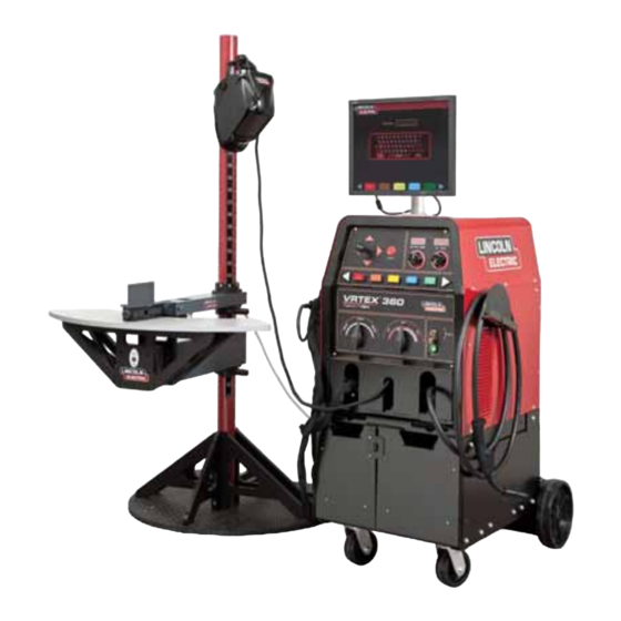
is a virtu-
VRTEX
360
®
al reality arc welding
training machine only
and NOT a real arc
welder. When welding
with arc welding equip-
ment, be aware of all
standard safety practices
associated with arc weld-
ing.
Some standard
warnings are included in
this manual.
• Sales and Service through Subsidiaries and Distributors Worldwide •
Cleveland, Ohio 44117-1199 U.S.A. TEL: 888.935.3878 FAX: 216.383.8823 WEB SITE: www.VRTEX360.com
VRTEX
AD1332-1
AD1332-2
AD1332-4
AD1332-5
OPERATOR'S MANUAL
• World's Leader in Welding and Cutting Products •
360
®
Software Version 1.2.4
Copyright © Lincoln Global Inc.
IM10046-E
October 2012
Advertisement
Table of Contents

Subscribe to Our Youtube Channel
Related Manuals for Lincoln Electric VRTEX 360 AD1332-1


Summary of Contents for Lincoln Electric VRTEX 360 AD1332-1
- Page 1 IM10046-E VRTEX October 2012 ® AD1332-1 Software Version 1.2.4 For use with machines having Code Numbers: AD1332-2 AD1332-4 AD1332-5 Safety Depends on You Lincoln equipment is designed and built with safety in mind. However, your overall safety can be increased by proper installa- tion ...
- Page 3 THANK YOU FOR SELECTING A QUALITY PRODUCT BY KEEP YOUR HEAD OUT OF THE FUMES. DON’T get too close to the arc. LINCOLN ELEC TRIC. Use corrective lenses if necessary to stay a reasonable distance away from the arc. READ and obey the Safety Data PLEASE EXAMINE CARTON AND EQUIPMENT FOR Sheet (SDS) and the warning label DAMAGE IMMEDIATELY...
- Page 4 W117.2-1974. A Free copy of “Arc Welding Safety” booklet E205 is available from the Lincoln Electric Company, 2.d. All welders should use the following procedures in order to 22801 St. Clair Avenue, Cleveland, Ohio 44117-1199.
- Page 5 SAFETY ELECTRIC SHOCK ARC RAYS CAN BURN. CAN KILL. 3.a. The electrode and work (or ground) circuits are 4.a. Use a shield with the proper filter and cover plates to protect your electrically “hot” when the welder is on. Do eyes from sparks and the rays of the arc when welding or not touch these “hot”...
- Page 6 SAFETY WELDING AND CUTTING CYLINDER MAY EXPLODE IF SPARKS CAN CAUSE DAMAGED. FIRE OR EXPLOSION. 7.a. Use only compressed gas cylinders containing the correct shielding gas for the process used 6.a. Remove fire hazards from the welding area. If and properly operating regulators designed for this is not possible, cover them to prevent the welding sparks the gas and pressure used.
- Page 7 SAFETY 5. Toujours porter des lunettes de sécurité dans la zone de PRÉCAUTIONS DE SÛRETÉ soudage. Utiliser des lunettes avec écrans lateraux dans les zones où l’on pique le laitier. Pour votre propre protection lire et observer toutes les instructions et les précautions de sûreté...
- Page 8 SAFETY Do not place objects on the VR Table, Arm or Seizures may cause loss of consciousness or convul- sions that can lead to injury from falling down or strik- Weld Machine. ing nearby objects. Handle the Face Mounted Display (FMD) integrat- Do not use the FMD when you are drowsy or fatigued.
- Page 9 SAFETY Recycling Welding Equipment at End of Life Waste Electrical and Electronic Equipment (WEEE) Recycling Recycling and reclamation of used electrical and electronic equipment is important to many nations and localities. Lincoln Electric provides information to assist in the recycling of welding equipment. This parts list contains a “WEEE”...
-
Page 10: Table Of Contents
viii viii TABLE OF CONTENTS Page Installation .......................Section A Graphic Symbols ........................A-1 Technical Specifications .......................A-2 Safety ...........................A-3 Location ..........................A-3 Environmental Area ......................A-3 Stacking/Tilting/Lifting ......................A-3 High Frequency Interference Protection................A-3 General Description......................A-4 Design Features ........................A-4 Hardware Uncrating & Set-up ..................A-4/A-7 ________________________________________________________________________________ Operation ......................Section B Product Description ......................B-1 User Interface Overview .......................B-2 Hardware Specifications ....................B-3/B-5... - Page 11 INSTALLATION GRAPHIC SYMBOLS THAT APPEAR ON THIS MACHINE OR IN THIS MANUAL INPUT POWER INPUT VOLTAGE INPUT CURRENT PROTECTIVE GROUND WARNING or CAUTION CIRCUIT BREAKER Documentation must be con- sulted in all cases where this symbol is displayed. INPUT POWER Explosion SINGLE PHASE ALTERNATING CURRENT...
-
Page 12: Installation
INSTALLATION TECHNICAL SPECIFICATIONS: AD1332-1,-4 (STD. FREQ.) / AD1332-2, -5 (ALT. FREQ.) ™ VRTEX 360 - VIRTUAL REALITY WELDING TRAINER INPUT MAKE/MODEL DESCRIPTION INPUT VOLTAGE INPUT CURRENT +/- 10% (MAX.) AD1332-1, -4 Standard Frequency 115-230 VAC (50-60 HZ) 4A-2A Single Phase AD1332-2, -5 Alternate Frequency 115-230 VAC (50-60 HZ) -
Page 13: Safety
INSTALLATION READ ENTIRE INSTALLATION SECTION BEFORE STACKING STARTING INSTALLATION. The VRTEX 360 cannot be stacked. ® Safety Precautions TILTING WARNING Place the VRTEX 360 directly on a secure, level sur- ® face. ELECTRIC SHOCK can kill. • Only qualified personnel should per- LIFTING form this installation. -
Page 14: General Description
INSTALLATION HARDWARE UNCRATING: GENERAL DESCRIPTION TOOLS NEEDED 3/8” (9.5 mm) Wrench The VRTEX 360 is a Virtual Welding Training System ® 3/16” (4.8 mm) Allen Wrench and VRAW (Virtual Reality Arc Welding) Solution. ® Phillips Screwdriver This computer controlled interactive system simulates arc welding through the use of realistic puddle graph- 1. - Page 15 INSTALLATION 2. Using the 3/8” (9.5 mm) wrench, remove the screws 7. Carefully cut and remove plastic wrapping. from the upper and lower front panels on the ship- 8. Remove the monitor from the front of the machine. ping crate. NOTE: Do not remove rear panel.
- Page 16 INSTALLATION 5. Obtain the three post T pins from the factory pack- Screws aging of the VRTEX 360. ® Table Swing Arm Post Table Base Pins Weights TABLE & SWING ARM SET-UP: 6. Insert one of the pins into the post at the #6 loca- tion.
- Page 17 INSTALLATION BACK OF MACHINE 9. Carefully slide swing-arm onto post with the letters (on the collar) “ABC” up and the grey cable located on the bottom of the swing arm assembly. 10. Insert a third T pin at a convenient height for hold- ing the helmet.
-
Page 18: Product Description
OPERATION PRODUCT DESCRIPTION The VRTEX 360 is a virtual reality arc welding train- ® Access panels are not to be removed except by quali- ing machine only and NOT a real arc welding fied service personnel due to risk of electric shock machine. -
Page 19: User Interface Overview
OPERATION USER INTERFACE OVERVIEW 10. The key switch is located on the lower right of the control panel. When the system is in the login The VRTEX 360 is a virtual reality arc welding train- ® screen the instructor may insert the key shipped er. - Page 20 OPERATION HARDWARE SPECIFICS: In order to strike an arc with the VR SMAW device, strike or tap the tip of the rod (of the VR SMAW device) on the coupon being welded. To break the VR GMAW/FCAW GUN arc, move the VR SMAW device rod away from the The VR gun has a trigger that is used during the simu- work piece.
- Page 21 FMD for approxi- ment. Run mately 10 minutes to clear The coupons along with the VR SMAW device and VR up moisture from the lenses. GMAW/FCAW gun have been factory calibrated at LENSES Lincoln Electric. VRTEX ®...
- Page 22 OPERATION Stand SWING ARM ROTATION The stand is comprised of the post, arm, table, Three pins, base and two weights. Users should position themselves at the stand during virtual welding. Post The arm and table slide up and down and rest on the collar pins that are inserted into the post.
-
Page 23: Login Screen
OPERATION However, users can set and use their own tolerances Powering Up Your System: for teaching beginner welders. The tolerances also 1. After you have set up the hardware and have determine how the user is scored on such parameters become familiar with the user controls, you will be as work angle, travel angle, travel speed, position, ready to use your system. - Page 24 OPERATION Press the orange language menu button again to exit Login Screen: the language menu. The system stores the language Overview selection and will automatically start up in the same lan- This page allows the user to: guage the next time. •...
- Page 25 OPERATION Joint Configuration Selection Screen: 7. Theory Button Screen Overview Overview The user selects which joint configuration they want to The THEORY button has been implemented to assist virtually weld. First, the user selects the joint and users with additional content, images and information position.
- Page 26 OPERATION Process Selection Screen: Stand Set-Up Screen: Overview Overview The correct VR stand information must be put into This screen allows the user to select the welding the software for the VRTEX 360 to operate prop- ® processes. To change among VR GMAW, VR FCAW, erly in all virtual welding applications.
- Page 27 B-10 B-10 OPERATION Table/Arm Rotation Pin Positions Move the physical VR table and arm to the desired When the physical stand is in the desired position, location for the position and joint configuration select- proceed with the following: Use the joystick and red ed.
- Page 28 B-11 B-11 OPERATION Indicate the coupon orientation used on the physical ENVIRONMENT SCREEN stand in the coupon rotation area of the stand setup screen. The red arrow indicates which side of the coupon that the weld will be made. For pipe configu- rations, the coupon rotation is replaced with arm angle.
- Page 29 B-12 B-12 OPERATION Weld Machine Settings Screen: The user will then have to change any settings that Overview are not correct. If the settings are correct and the green check settings button is pressed, the welderʼs The user must enter the proper welding procedure view screen will appear on the monitor and in the hel- and process settings, including wire feed speed, metʼs stereo visor.
-
Page 30: Push Buttons
B-13 B-13 OPERATION Upper Overlays The “Cheater” Lens magnifies the image as seen by the user in the helmet and in the welderʼs view. The The welding technique set in the tolerance editor and user can toggle between Off, 1.25X, 1.5X, 1.75X, 2X other process details are displayed on the upper right select their option with the red select button. -
Page 31: Travel/Work Angle
B-14 B-14 OPERATION The Arc Length cue is similar to the CTWD cue but The Whip cue can be used with the E6010 VR SMAW represents arc length distance for the VR SMAW process. This cue helps the student use correct spac- process. -
Page 32: Instructors View
B-15 B-15 OPERATION LASER SCREEN New Coupon (Live Action Student Evaluation Report) Pressing the blue new coupon menu button instantly replaces the current coupon with a fresh, unwelded Overview coupon. Note that this is a quick way to start over on This screen summarizes the studentʼs welding perfor- the same configuration and process but that it will mance. -
Page 33: Technique Parameters
B-16 B-16 OPERATION LASER SCREEN (GRAPH, DEFECTS, DISCONTINUITIES, ETC.) TECHNIQUE PARAMETERS The upper left area of the screen shows the technique parameters being tracked and the graph of these parame- ters is located to the right. When the user welds, each parameter is graphed using a line that is of the same color as the technique parameter box. - Page 34 B-17 B-17 OPERATION Position is the userʼs ideal weld root location. This Travel Angle is the angle between the electrode and location can change with each pass. When weaving, the workpiece in the direction of travel. The upper right the ideal location is considered the centerline of the area of the screen displays if the user should be push- weave.
- Page 35 B-18 B-18 OPERATION Travel Speed is how fast the electrode is traveling in Bead Render respect to the workpiece. An image of the completed pass appears in the mid- dle of the screen. Dime Spacing is the distance from one solidified weld puddle to the next.
-
Page 36: Instructor Mode
B-19 B-19 OPERATION End Pass This can be done on most screens by pressing menu, logout, and selecting yes. Then the user must place the When the user presses the green “End Pass” menu button, key into the turn key slot at the front of the weld machine the pass is scored, a snapshot of the weld is taken, and the and rotate the key 90 degrees to the right. -
Page 37: License Information
® For more information on the VRTEX 360 Upgrade ® the MAC Address, or computer address of each Program, please contact your Lincoln Electric sales machine specifically. representative or the Lincoln Electric Automation Division. TEL: 1-216-481-8100, Ask for the LICENSE INFORMATION SCREEN Automation Division. -
Page 38: Tolerance Editor
B-21 B-21 OPERATION Base Metal tracks how many virtual coupons have Tolerance Editor been used and their cumulative weight. Note that Overview plate 3/8” includes groove joints as well as T-joints, The tolerance editor allows users to modify the sys- while plate 10GA. -
Page 39: Choosing Tolerance Set-Up
B-22 B-22 OPERATION Choose Tolerance Set-up USB Edit This displays the list of all tolerance settings currently stored on the unit. All units ship with default settings. This menu relates only to the files on the USB memo- If the user creates multiple tolerance files, the file in ry device. - Page 40 B-23 B-23 OPERATION TOLERANCES SELECTED (DEFAULTS) Back Pressing Back goes back to the previous screen. Continue Pressing Continue goes to the tolerance process selection screen. Tolerances Process Selection Screen Overview The user selects which process to modify. TOLERANCES PROCESS SELECTION SCREEN Back Pressing back returns the user to the previous page screen.
- Page 41 B-24 B-24 OPERATION Next Pass Modifying Tolerances The next pass button changes the pass being modi- Overview fied to the next pass in the series. If this is the last The user can modify the tolerance values. This is pass, this option will not be available. done by: 1) Use the joystick to highlight the equipment setting Tolerances Equipment Settings...
- Page 42 B-25 B-25 OPERATION Tolerances Welding Technique Tolerances Pattern and Aim Screen Parameters Screen Overview This screen allows the user to change the type of pat- Overview tern being used (stringer, box weave, straight weave, This screen allows the modification of: whip, triangle weave) and the position of the root of •...
-
Page 43: Tolerances Whip & Travel Speed
B-26 B-26 OPERATION Tolerances Whip and Travel Speed Screen Overview This screen allows for the modification of technique parameter relating to the whipping welding technique and travel speed including: • Dime Spacing • Whip Time • Puddle Time • Travel Speed WHIP &... -
Page 44: Vrtex Vrtex
360. The VRTEX 360 Upgrade ® ® Program can be purchased from Lincoln Electric. The upgrade packages are sent directly to customers who purchase them with supporting literature, materials and curriculum components to be used in any welding train- ing environment. For more information on the VRTEX ®... - Page 45 B-28 B-28 OPERATION Selecting Root or Face: Once the first sample has been bent, use the white NEXT or PREV arrow buttons to select the next tab to bend. Use the joystick to highlight and toggle between the GREEN TO BEND ROOT and FACE bend.
- Page 46 B-29 B-29 OPERATION Failed The bent sample can also be rotated for further visual inspection by using the joystick. FaceBend visual inspection Passed. FaceBend Visual Passed Percentages of RootBend Failure BEND TEST FAILURE: The VRTEX 360 will visually inspect the weld before ®...
- Page 47 B-30 B-30 OPERATION EXITING THE BEND TEST: THE CERTIFICATE: To exit the bend test application, press the red MENU The BEND TEST CERTIFICATE is located in the button and use the joystick to toggle to YES then STUDENT REPORT, which can be saved and press the red SELECT button.
- Page 48 B-31 B-31 OPERATION SCORING MODULES: Scoring Modules Select Button Overview: After welding a pass, the user can now see whether each defect/discontinuity was within acceptable stan- dards (passed) or not (failed). The acceptable stan- dards implemented in VRTEX 360 are known as ®...
- Page 49 B-32 B-32 OPERATION Overview: Selects Visual Cues or Action The Visual Cues and Actions that have been selected by the user will now appear as icons on the LASER screen below the Discontinuities window. The icons will remain ghosted until the user selects the option to use the Visual Cue or Action.
- Page 50 B-33 B-33 OPERATION PANNING MODE: Overview: The panning view function enhances the instructor’s ability to view a weldment as a student welds to better train the student on proper welding technique. Three modes that include rotate, zoom and pan are now available.
- Page 51 Overview: The License Screen: The License Agreement is an agreement to the terms and conditions on which Lincoln Electric grants to the The License screen allows the user to view the business entity registered with Lincoln on the pur- upgrades that are unlocked with a brief description for chase of the Software (“Software Licensee”), a non-...
- Page 52 B-35 B-35 OPERATION GETTING TO THE EULA Material Selection Arrows Saving the EULA to a USB can be done by plugging a USB memory device into the USB port next to the Instructor Key slot and selecting the blue “Save to USB”...
- Page 53 B-36 B-36 OPERATION The gas selection for the aluminum welding process is REPLAY MODE: 100% Argon. To select this gas use the joystick up Overview: motion to highlight 100% Argon and press the red “Select” button. The next step is to set the gas flow The Video Replay feature in your VRTEX 360 pro- rate.
- Page 54 B-37 B-37 OPERATION LEARNING LEVELS: Entry Level Tolerance Selection Overview: The Learning Levels, or Tolerance Level, feature in your VRTEX 360 provides 3 skill levels (Entry Level, Intermediate and Advanced) for students in your weld- ing training program. As the progression of skills and capabilities progress, you can enable different levels to keep students challenged, excited and engaged in learning.
- Page 55 B-38 B-38 OPERATION Advanced: Any additional tolerance settings that have been cre- The “Advanced” Learning Level is designed to be the ated by the user will also appear in this box. Those most challenging. This level is for the student that has tolerance settings can still be accessed and changed more welding experience.
- Page 56 B-39 B-39 OPERATION VRTEX ®...
-
Page 57: Maintenance
MAINTENANCE CLEANING & MAINTENANCE Taking proper care of the FMD (Face Mounted Display) is important for optimal functioning of the equipment. Occasionally, the FMD lens should be wiped with the lint free lens wipe that is provided. This can be done to remove fingerprints from the lens- es. -
Page 58: Troubleshooting
HOW TO USE TROUBLESHOOTING GUIDE WARNING Service and Repair should only be performed by Lincoln Electric Factory Trained Personnel. Unauthorized repairs performed on this equipment may result in danger to the technician and machine operator and will invalidate your factory warranty. For your safety and to avoid Electrical Shock, please observe all safety notes and precautions detailed throughout this manual. -
Page 59: Wiring Diagrams
TROUBLESHOOTING Observe all Safety Guidelines detailed throughout this manual PROBLEMS POSSIBLE RECOMMENDED (SYMPTOMS) CAUSE COURSE OF ACTION There is jitter, shake or wobble in the Make sure the helmet is close to the Check for loose or faulty connections Helmet display and Monitor. work piece. - Page 60 TROUBLESHOOTING Observe all Safety Guidelines detailed throughout this manual PROBLEMS POSSIBLE RECOMMENDED (SYMPTOMS) CAUSE COURSE OF ACTION Previous weld pass data is not “End Pass” must be activated before Use the joystick to go to pass num- accessible on the LASER screen. starting a new pass.
- Page 61 DIAGRAMS VRTEX ®...
- Page 62 DIAGRAMS VRTEX ®...
- Page 63 Do not touch electrically live parts or Keep flammable materials away. Wear eye, ear and body protection. WARNING electrode with skin or wet clothing. Insulate yourself from work and ground. Spanish No toque las partes o los electrodos Mantenga el material combustible Protéjase los ojos, los oídos y el AVISO DE bajo carga con la piel o ropa moja-...
- Page 64 Keep your head out of fumes. Turn power off before servicing. Do not operate with panel open or WARNING Use ventilation or exhaust to guards off. remove fumes from breathing zone. Spanish Los humos fuera de la zona de res- Desconectar el cable de ali- No operar con panel abierto o AVISO DE...
- Page 65 • World's Leader in Welding and Cutting Products • • Sales and Service through Subsidiaries and Distributors Worldwide • Cleveland, Ohio 44117-1199 U.S.A. TEL: 216.481.8100 FAX: 216.486.1751 WEB SITE: www.lincolnelectric.com...
Need help?
Do you have a question about the VRTEX 360 AD1332-1 and is the answer not in the manual?
Questions and answers