
Subscribe to Our Youtube Channel
Related Manuals for MCZ BOXTHERM 70 AIR 9 BASIC M1


Summary of Contents for MCZ BOXTHERM 70 AIR 9 BASIC M1
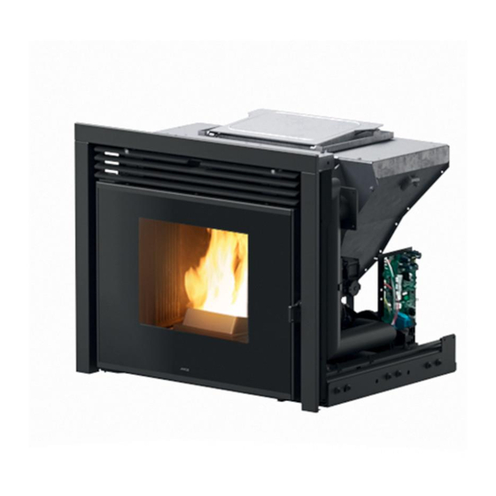
- Page 1 INSTALLATION GUIDE INSERT BOXTHERM 70 AIR 9 BASIC M1 BOXTHERM 70 AIR 9 SLIDE M1 BOXTHERM 60 AIR 6 BASIC M1 BOXTHERM 60 AIR 6 SLIDE M1 PART 1 - REGULATIONS AND ASSEMBLY Instructions in English...
-
Page 2: Table Of Contents
TABLE OF CONTENTS TABLE OF CONTENTS TABLE OF CONTENTS ....................II INTRODUCTION ......................1 1-WARNINGS AND WARRANTY CONDITIONS ..............2 2-INSTALLATION ......................8 3-DRAWINGS AND TECHNICAL FEATURES ..............17 4-UNPACKING ......................25 5-OVERALL DIMENSIONS ...................26 6-PRELIMINARY STEPS ....................30 7-TYPE OF FASTENING ....................33 8-ACCESSORIES ......................40 9-ASSEMBLING THE ACCESSORIES ................43 10-EXTRACTING INSERT AND LOADING PELLETS IN COLD MACHINE ......50 11-DOOR OPENING ....................56 12-ELECTRICAL CONNECTION ..................57... -
Page 3: Introduction
REVISIONS TO THE PUBLICATION The content of this manual is strictly technical and the property of MCZ Group Spa. No part of this manual may be translated into other languages, adapted or reproduced, even in part, in other mechanical or electronic forms, photocopies, recordings or other, without the prior written authorisation from MCZ Group Spa. -
Page 4: 1-Warnings And Warranty Conditions
1-WARNINGS AND WARRANTY CONDITIONS SAFETY PRECAUTIONS • Installation, electrical connection, operating test and maintenance must only be carried out by authorised and qualified personnel. • Install the product in accordance with all local and national legislation and regulations in force in the region or state. • Only use the fuel recommended by the manufacturer. - Page 5 1-WARNINGS AND WARRANTY CONDITIONS • Do not put linen on the product to dry. Any drying racks or the like must be kept at a safe distance from the product. Fire hazard. • All liability for improper use of the product is entirely borne by the user and relieves the Manufacturer of any civil and criminal liability.
- Page 6 1-WARNINGS AND WARRANTY CONDITIONS • The product and the cladding must be stored in a dry place and must not be exposed to weathering. • It is recommended not to remove the feet that support the product in order to guarantee adequate insulation, especially if the flooring is made of flammable materials.
- Page 7 1-WARNINGS AND WARRANTY CONDITIONS INFORMATION: Please contact the retailer or qualified personnel authorised by the company to resolve a problem. • You must only use the fuel specified by the manufacturer. • When the product is switched on for the first time it is normal for it to emit smoke due to the paint heating for the first time. Therefore make sure the room in which it is installed is well ventilated.
- Page 8 1-WARNINGS AND WARRANTY CONDITIONS Installations that do not meet the current standards, improper use and lack of maintenance as expected by the manufacturer, void the product warranty. The warranty is valid on the condition that the instructions and warnings contained in the user and maintenance manual are observed, and therefore the product is used correctly.
- Page 9 1-WARNINGS AND WARRANTY CONDITIONS SPARE PARTS In the event of a malfunction, consult the retailer who will forward the call to the Technical Assistance Department. Only use original spare parts. The retailer or service centre can provide all necessary information regarding spare parts. We do not recommend waiting for the parts to get worn out before having them replaced.
-
Page 10: 2-Installation
2-INSTALLATION The instructions in this chapter refer explicitly to the Italian installation regulation UNI 10683. In any case, always observe the regulations in force in the country of installation. PELLETS Wood pellets are manufactured by hot-extruding compressed sawdust which is produced during the working of natural dried wood. The compactness of the material is guaranteed by the lignin contained in the wood itself and allows pellets to be produced without glue or binders. - Page 11 2-INSTALLATION FOREWORD The installation position must be chosen according to the room, smoke extraction system and flue. Check with local authorities whether there are any restrictive regulations in force regarding the combustion air inlet, the smoke outlet system, the flue or the chimneypot. The manufacturer declines all responsibility in the event of installations that do not comply with the laws in force, incorrect room air exchange, electrical connection non-compliant with the standards and inappropriate use of the appliance.
- Page 12 2-INSTALLATION FOREWORD The Flue chapter has been drawn up with reference to the provisions of European Standards (EN13384 - EN1443 - EN1856 - EN1457). The chapter provides indications for installing an efficient and correct flue but is under no circumstances to substitute the regulations in force, which the qualified technician must be in possession of.
- Page 13 2-INSTALLATION TECHNICAL CHARACTERISTICS Have the efficiency of the flue checked by an authorised technician. The flue must be sealed against flue gasses, in a vertical direction without narrowing, be made with materials impermeable to smoke, condensation, thermally insulated and suitable to resist normal mechanical stress over time (we recommend fireplaces made of A/316 or refractory material with insulated round section double chamber).
- Page 14 2-INSTALLATION ROOF AT 60° ROOF AT 45° 45° 60° A = MIN. 2.60 metres A = MIN. 2.00 metres FIGURE 5 FIGURE 6 B = DISTANCE > 1.20 metres B = DISTANCE > 1.30 metres C = DISTANCE < 1.20 metres C = DISTANCE <...
- Page 15 2-INSTALLATION MAINTENANCE The flue must be kept clean, since the deposit of soot or unburnt oils reduces the cross-section reducing the draught and thus compromising the efficient operation of the stove and, if large build-ups accumulate, can catch fire. The flue and chimneypot must be cleaned and checked by a qualified chimney sweep at least once a year.
- Page 16 2-INSTALLATION EXTERNAL AIR INLET It is mandatory to provide an adequate external air inlet that supplies the combustion air required for the product to work properly. The flow of air between the outside and the installation room may be direct, through an inlet in an external wall of the room (preferable solution see Figure 9 a);...
- Page 17 2-INSTALLATION DISTANCE (metres) The air inlet must be at a distance of: 1.5 m BELOW Windows, doors, smoke outlets, cavities, ..1.5 m HORIZONTALLY Windows, doors, smoke outlets, cavities, ..0.3 m ABOVE Windows, doors, smoke outlets, cavities, ..1.5 m AT A DISTANCE from smoke outlet CONNECTION TO THE FLUE...
- Page 18 2-INSTALLATION EXAMPLES OF CORRECT INSTALLATION 1. Installation of Ø120mm flue with hole for the passage of the pipe increased by: minimum 100mm around the pipe if next to non flammable parts such as cement, brick, etc.; or minimum 300mm around the pipe (or as required by rating plate) if next to flammable parts such as wood etc.
-
Page 19: 3-Drawings And Technical Features
3-DRAWINGS AND TECHNICAL FEATURES DRAWINGS AND CHARACTERISTICS BOXTHERM 70 AIR 9 BASIC M1 DIMENSIONS (dimensions in mm) Ø80 Ø80 Technical Dept. - All rights reserved - Reproduction prohibited... - Page 20 3-DRAWINGS AND TECHNICAL FEATURES BOXTHERM 70 AIR 9 SLIDE M1 DIMENSIONS (dimensions in mm) Ø80 Ø80...
- Page 21 3-DRAWINGS AND TECHNICAL FEATURES BOXTHERM 70 AIR 9 SLIDE M1 DIMENSIONS (dimensions in mm) + LINK KIT (optional) 272 Ø210 272 Ø80 Technical Dept. - All rights reserved - Reproduction prohibited...
- Page 22 3-DRAWINGS AND TECHNICAL FEATURES BOXTHERM 60 AIR 6 BASIC M1 DIMENSIONS (dimensions in mm) Ø80 Ø80...
- Page 23 3-DRAWINGS AND TECHNICAL FEATURES BOXTHERM 60 AIR 6 SLIDE M1 DIMENSIONS (dimensions in mm) Ø80 Ø80 Technical Dept. - All rights reserved - Reproduction prohibited...
- Page 24 3-DRAWINGS AND TECHNICAL FEATURES BOXTHERM 60 AIR 6 SLIDE M1 DIMENSIONS (dimensions in mm) + LINK KIT (optional) Ø210 Ø80...
- Page 25 3-DRAWINGS AND TECHNICAL FEATURES TECHNICAL CHARACTERISTICS BOXTHERM 70 AIR 9 BASIC M1 / BOXTHERM 70 AIR 9 SLIDE M1 Energy Efficiency Class Nominal output power 8.8 kW (7568 kcal/h) Minimum power output 2.5 kW (2150 kcal/h) Efficiency at Max 90.6% Efficiency at Min 94.1%...
- Page 26 3-DRAWINGS AND TECHNICAL FEATURES TECHNICAL CHARACTERISTICS BOXTHERM 60 AIR 6 BASIC M1 / BOXTHERM 60 AIR 6 SLIDE M1 Energy Efficiency Class Nominal output power 5.9 kW (5074 kcal/h) Minimum power output 2.2 kW (1892 kcal/h) Efficiency at Max 91.0% Efficiency at Min 94.7% Temperature of exhaust smoke at Max...
-
Page 27: 4-Unpacking
4-UNPACKING PREPARATION AND UNPACKING The product is supplied in a single package. Open the package, remove any straps, cardboard and polystyrene and take the appliance off the pallet. To remove the product from the pallet you must extract the movable part of the insert and take out the four Phillips screws securing it to the pallet. -
Page 28: 5-Overall Dimensions
5-OVERALL DIMENSIONS BOXTHERM BASIC VERSION vedi disegno BOXTHERM 70/60 vedi disegno BOXTHERM 70/60 BOXTHERM BASIC (Pianta) vedi disegno BOXTHERM 70/60 vedi disegno BOXTHERM 70/60 INSERT SUPPORT (existing or new) WALL INSULATION SAFETY DISTANCE FROM COMBUSTIBLE MATERIAL... - Page 29 5-OVERALL DIMENSIONS BOXTHERM SLIDE VERSION vedi disegno BOXTHERM 70/60 vedi disegno BOXTHERM 70/60 BOXTHERM SLIDE (Pianta) vedi disegno BOXTHERM 70/60 vedi disegno BOXTHERM 70/60 INSERT SUPPORT (existing or new) WALL INSULATION SAFETY DISTANCE FROM COMBUSTIBLE MATERIAL Technical Dept. - All rights reserved - Reproduction prohibited...
- Page 30 5-OVERALL DIMENSIONS EXAMPLE OF PLACEMENT AT A 90° ANGLE...
- Page 31 5-OVERALL DIMENSIONS EXAMPLE OF PLACEMENT AT A 45° ANGLE Technical Dept. - All rights reserved - Reproduction prohibited...
-
Page 32: 6-Preliminary Steps
6-PRELIMINARY STEPS COMBUSTION AIR During operation a certain amount of air is drawn from the room in which the product is installed and this air must be supplemented through an external air inlet. The combustion air “B” in this product is autonomously drawn directly from the front grille, however, the user can have the air drawn from outside by connecting pipe “A”... - Page 33 6-PRELIMINARY STEPS PRELIMINARY STEPS Proceed as follows to unlock the fixed part of the insert: • remove the two nuts “d” and the two roses “r” from the right and left of the insert to make it easier to hold, take the two optional handles “M” and fasten them to the insert •...
- Page 34 6-PRELIMINARY STEPS • the handles “M” are now fastened on the insert; hold the two handles “M” and lift the insert • the fixed part “A” is now free and you can fasten it onto the optional support or on an existing surface (as explained in the next pages)
-
Page 35: 7-Type Of Fastening
7-TYPE OF FASTENING HOW TO FASTEN THE INSERT It is obligatory to anchor the product to a surface during annual maintenance operations by the authorised technician, or when the fuel is loaded, the combustion chamber may be extracted from its seat with the aid of two retractable guides. The product can be anchored to an existing surface (which must have certain characteristics) or it can be fastened to the optional support. - Page 36 7-TYPE OF FASTENING Fastening to an existing surface POSITION DESCRIPTION BOXTHERM FIXED INSERT PART EXISTING SURFACE ANCHOR BOLT (SEE PREVIOUS PAGE) WASHERS If installing on an existing surface, provided with grille “G” (see next pages), it is strongly recommended to fasten it according to the diagram.
- Page 37 7-TYPE OF FASTENING Fastening to the horizontal support Place the base in the desired position (after mounting it as explained in the instructions attached to the accessory) and adjust the height with the feet (from a min. of 500 mm to a max. of 650 mm). Make sure there is a power socket behind the pedestal so that the plug is accessible after the unit has been installed.
- Page 38 7-TYPE OF FASTENING INSTALLING BOXTHERM ON EXISTING CHIMNEY AIR INTAKE GRILLE IN THE BEST POSITION The best position for the air intake grille “G” is in the centre of the existing firebox with the measurements shown in the table. BOXTHERM 60 BOXTHERM 70 MIN 190 MIN 200...
- Page 39 7-TYPE OF FASTENING AIR INTAKE GRILLE ON THE LEFT If the position of the air intake grille “G” is on the left of the firebox, it needs to be changed and moved towards the centre of the firebox in the best position. The opening of the existing firebox must nevertheless have the measurements shown on the previous page. POS.1 PIT H60 mm MIN.
- Page 40 7-TYPE OF FASTENING FASTENING TO THE EXISTING FIREBOX WITHOUT AIR OPENINGS If the existing firebox does not have any air openings (see next pages), you must use the “Feet kit” accessory (optional). Follow the procedure below to position it: • After separating the fixed part “A”...
- Page 41 7-TYPE OF FASTENING • pick the rubber strip “v” up, remove the adhesive film and fix it under the piece “A” cut to size flush with the outer perimeter of the part “A” • Pick the piece “A” up with the rubber strip “v” stuck on it and place it on the feet “w” •...
-
Page 42: 8-Accessories
8-ACCESSORIES ACCESSORIES LINK KIT To be combined with the BOXTHERM SLIDE version. The hatch is for loading the pellets and can be positioned to the side or front of the Boxtherm. COMBUSTION AIR KIT This can be combined with any Boxtherm version and is used to remove the combustion air from the external environment. - Page 43 8-ACCESSORIES 4-SIDED FRAME This can be combined with any Boxtherm version. Pellet level sensor Used to measure the level of pellets in the tank. Support Used to position the Boxtherm at the required height without using an existing surface. Technical Dept. - All rights reserved - Reproduction prohibited...
- Page 44 8-ACCESSORIES Feet kit To be used if installing with an existing surface to allow the cooling air to flow correctly. The kit consists of: a seal, 4 feet and relative screws and closing profile. Maestro panel...
-
Page 45: 9-Assembling The Accessories
9-ASSEMBLING THE ACCESSORIES ASSEMBLING LINK KIT ON BOXTHERM SLIDE VERSION The Link kit can only be installed on the SLIDE version. To install the kit proceed as follows: • unscrew the three screws “k” to remove the two sides “G” •... - Page 46 9-ASSEMBLING THE ACCESSORIES • behind the tilted combustion air pipe “T”, remove the two screws “o” securing the tank cover to the structure (on the right and left of the product) • lift the pellet tank cover “S” and remove the eight screws “w” • now remove the entire top cover “P”...
- Page 47 9-ASSEMBLING THE ACCESSORIES Attention! the top part of the piece “V” must face the BOXTHERM firebox door • Take the piece “H” from the kit and fasten it onto the right side with the four screws “k” Technical Dept. - All rights reserved - Reproduction prohibited...
- Page 48 9-ASSEMBLING THE ACCESSORIES • Take the piece “P” and fasten it to the left side of the Boxtherm with the two screws “x” • Then take the cover “L” and attach it to “H” with the screws “x” and to the piece “P” with the two screws “w”. Make sure the cover “L” presses on the seal “J”...
- Page 49 9-ASSEMBLING THE ACCESSORIES • prepare the hole in the wall to fasten the loader “M” (394*259 mm) • Lastly, connect the two ends with the pipe “O” and block it with the two clamps “f” Boxtherm 60 Boxtherm 70 Technical Dept. - All rights reserved - Reproduction prohibited...
- Page 50 9-ASSEMBLING THE ACCESSORIES ASSEMBLING COMBUSTION AIR KIT Only in the SLIDE version, unscrew the three screws “k” to remove the protection panel “G”. Assemble as follows: • Unscrew the two screws “x” to remove the front grille “C” • take the plate “u” from the optional air kit and fasten it to the structure with the two screws “y”...
- Page 51 9-ASSEMBLING THE ACCESSORIES If installing the air kit with the link kit, you must: • take the plate “p” out of the air kit and remove the two screws “x” • fasten the air kit directly on the link kit support with the screws “y” Continue fastening as explained on the previous page for the other versions.
-
Page 52: 10-Extracting Insert And Loading Pellets In Cold Machine
10-EXTRACTING INSERT AND LOADING PELLETS IN COLD MACHINE EXTRACTING INSERT AND LOADING PELLETS SLIDE VERSION The insert can be extracted in order to load pellets into the tank and perform routine maintenance (clean the ash pipe at the end of the year) or special maintenance (replacement of electrical parts if the product breaks) Follow the procedure below to extract the insert: •... - Page 53 10-EXTRACTING INSERT AND LOADING PELLETS IN COLD MACHINE Extraction of BASIC version insert Follow the procedure below to extract the insert: • open the fire door “C” using the cold handle “Z” supplied • loosen the nuts “X” so that the plate “M” comes out which stops the insert from being extracted • to extract the movable part, take hold of the insert by the door or by the inside of the firebox and pull it towards you When loading, do not let the pellet bag come into contact with hot surfaces.
- Page 54 10-EXTRACTING INSERT AND LOADING PELLETS IN COLD MACHINE BASIC VERSION • open the drawer “L” using the cold handle “Z” supplied. The guides of the tray have an end-of-travel that block the mobile part when extracted completely (approximately 20 cm). To open the drawer “L”...
- Page 55 10-EXTRACTING INSERT AND LOADING PELLETS IN COLD MACHINE Close the “L” drawer. Push by placing your hands where Close fully. illustrated. The drawer profile is flush with the frame. We recommend you try different ways of loading to understand how may actions are required with the tool “B”.
- Page 56 10-EXTRACTING INSERT AND LOADING PELLETS IN COLD MACHINE SLIDE VERSION • open the firebox door “C” using the handle “D” with the cold handle “Z” • open the handle “E” using the cold handle “Z” • extract the insert using the handle “H” •...
- Page 57 10-EXTRACTING INSERT AND LOADING PELLETS IN COLD MACHINE Attention! When the “STOVE OFF” status is displayed, wait 1.5 minutes before extracting the insert. Technical Dept. - All rights reserved - Reproduction prohibited...
-
Page 58: 11-Door Opening
11-DOOR OPENING DOOR OPENING To open the product door “C”, fit the cold handle “Z” into the hole in the handle and pull it towards you. Caution! The firebox door must be closed properly for the stove to work correctly. The door should only be opened with the product switched off and cold. -
Page 59: 12-Electrical Connection
12-ELECTRICAL CONNECTION ELECTRICAL CONNECTION First connect the power cable to the rear of the product and then to a wall socket, which must always remain accessible. Should this not be possible, during installation insert suitable devices for disconnection from the power mains, in compliance with national electrical installation standards. - Page 60 12-ELECTRICAL CONNECTION ROOM PROBE The roof probe is inside the firebox on the door opening side. Check that the room probe bulb is near to the holes on the frame.
-
Page 61: 13-Cladding
13-CLADDING SETTING UP THE CLADDING All product functionalities must be tested before being clad. The company cannot be held liable for any damage to the cladding should operating anomalies arise, which were not ascertained before the cladding was applied to the product. IT IS OBLIGATORY to check seal of all piping the smoke goes through (smoke fitting, gaskets and insert in the flue) before installing the cladding. - Page 62 13-CLADDING The machine must be insulated (panel K) so as not to receive air from the hood “Z” and counter- hood “Y”. The ventilation air “3” must only come from the bottom. 2 - rigid or solid filler panel (not mesh) 1 - a grille can be used to vent the hot air accumulated at the top of the product...
- Page 64 MCZ GROUP S.p.A. Via La Croce n°8 33074 Vigonovo di Fontanafredda (PN) – ITALY Telephone: 0434/599599 a.s. Fax: 0434/599598 Internet: www.mcz.it e-mail: mcz@mcz.it 8901879700 REV. 2 27/08/2019...
Need help?
Do you have a question about the BOXTHERM 70 AIR 9 BASIC M1 and is the answer not in the manual?
Questions and answers