Table of Contents
Advertisement
Quick Links
Advertisement
Table of Contents

Related Manuals for MCZ VIVO 70 WOOD


Summary of Contents for MCZ VIVO 70 WOOD
- Page 1 MANUALE DI USO ED INSTALLAZIONE 8901156000...
-
Page 2: Table Of Contents
CONTROL UNIT ..........................28 5.4. Composition of control unit .....................28 5.4.1. Positioning of the control unit....................28 5.4.2. GENERAL INFORMATION ON THE CONTROL UNIT ................29 5.5. On/off ...........................29 5.5.1. Contents Technical service – MCZ Group S.p.A. all rights reserved - Reproduction prohibited... - Page 3 Cleaning out the ashes ......................40 7.1.2. ® Cleaning the refractory material walls (ALUTEC ) ..............40 7.1.3. CLEANING TO BE DEALT WITH BY SPECIALIZED TECHNICIAN ............41 7.2. Cleaning flue pipe........................41 7.2.1. Contents Technical service – MCZ Group S.p.A. all rights reserved - Reproduction prohibited...
-
Page 4: Introduction
An essential item or one that requires specific attention is published in “bold”. “Italics" are used for any additional clarification. NOTE: the “NOTE” provides the reader with additional information on the subject. Introduction Technical service – MCZ Group S.p.A. all rights reserved - Reproduction prohibited... -
Page 5: Warnings And Warranty Conditions
"cold" activation devices. Incorrect installation or poor maintenance (not compliant with the provisions of this manual) Warnings and warranty conditions Technical service – MCZ Group S.p.A. all rights reserved - Reproduction prohibited... -
Page 6: Warranty Conditions
Warnings and warranty conditions Technical service – MCZ Group S.p.A. all rights reserved - Reproduction prohibited... -
Page 7: Installation In Accordance With Uni 10683
The room must be: suitable for room operating conditions equipped with an adequate smoke exhaust system equipped with outdoor ventilation Theoretical notions for installation Technical service – MCZ Group S.p.A. all rights reserved - Reproduction prohibited... -
Page 8: Connection To The External Air Intake
Theoretical notions for installation Technical service – MCZ Group S.p.A. all rights reserved - Reproduction prohibited... -
Page 9: Connection To The Flue Pipe
The flue pipe is of primary importance for the correct the external rising section. functioning and safety of your fireplace stove. Theoretical notions for installation Technical service – MCZ Group S.p.A. all rights reserved - Reproduction prohibited... -
Page 10: Examples Of Flue Pipes
MCZ technician inspect and measure chimney flue performance (micro-gauge measurements) MCZ s.p.a. shall not be held liable for poor operation of the fireplace stove that is due to a flue pipe of improper size or installation that does comply with provided requirements. -
Page 11: Cowl
2 m away. In any case, the cowl must exceed the peak of the roof by at least 1m. Theoretical notions for installation Technical service – MCZ Group S.p.A. all rights reserved - Reproduction prohibited... -
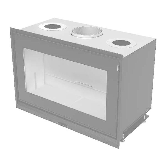
Page 12: Dimensions And Technical Specifications
Chapter 4 INSTALLATION AND USE MANUAL page 3. DIMENSIONS AND TECHNICAL SPECIFICATIONS Dimensions VIVO 70 WOOD 3.1. 450.5 16.5 D150 D150 D200 Installation and assembly Technical service – MCZ Group S.p.A. all rights reserved - Reproduction prohibited... -
Page 13: Dimensions Vivo 90 Wood
Chapter 4 INSTALLATION AND USE MANUAL page Dimensions VIVO 90 WOOD 3.2. 15 8.5 D150 D150 D200 11.5 11.5 Installation and assembly Technical service – MCZ Group S.p.A. all rights reserved - Reproduction prohibited... -
Page 14: Technical Specifications
Over 7 m 20x20 cm Ø20 Note Intermittent combustion unit Appliance suitable for installation in a shared flue. * Data may vary according to the fuel used Installation and assembly Technical service – MCZ Group S.p.A. all rights reserved - Reproduction prohibited... -
Page 15: Installation And Assembly
However, be sure to put all of the parts back in place. This operation is to be carried out only by specialized personnel. MCZ shall not be held liable if the preceding warning is not complied with. PREPARATION AND UNPACKING 4.1. -
Page 16: Natural Convection (Comfort Air Vn)
CONNECTING THE COMBUSTION AIR INTAKE Ø100 DIRECTLY TO AN EXTERNAL AIR INTAKE OR AT LEAST TO HAVE AIR DRAWN FROM OUTSIDE THE Figure 3 – Forced convection CLADDING. Installation and assembly Technical service – MCZ Group S.p.A. all rights reserved - Reproduction prohibited... -
Page 17: External And Internal Air Intake
This air intake A can also be located in the room where the stove unit is installed. Installation and assembly Technical service – MCZ Group S.p.A. all rights reserved - Reproduction prohibited... -
Page 18: Positioning
Figura 7 – Installation near flammable If the stove is positioned over a floor or close to material walls made of flammable materials, it is advisable to use sufficient insulation. Installation and assembly Technical service – MCZ Group S.p.A. all rights reserved - Reproduction prohibited... - Page 19 Chapter 4 INSTALLATION AND USE MANUAL page Vivo 70 Wood wall hole size Vivo 90 Wood wall hole size Installation and assembly Technical service – MCZ Group S.p.A. all rights reserved - Reproduction prohibited...
-
Page 20: Adjustment Of Height And Balancing
Marble or other material load-bearing structure and to make it easy to work in the event of future anomalies and/or maintenance. Figure 10 – Insulating a wooden beam Installation and assembly Technical service – MCZ Group S.p.A. all rights reserved - Reproduction prohibited... -
Page 21: Insulating A Wooden Beam
Grilles 1a and 1b are essential for releasing the heat that builds up in the hood. They must be installed, regardless of the type of installation or cladding to be realized. Installation and assembly Technical service – MCZ Group S.p.A. all rights reserved - Reproduction prohibited... -
Page 22: Comfort Air Kit- Natural Ventilation And Forced Ventilation
(2 pieces) 4. Flange Ø 100 VF (2 pieces) 2. Fastening bracket group (2 pieces) 5. Hose clamp D.60-170 (4 pieces) 6. Control unit Comfort air kit Technical service – MCZ Group S.p.A. all rights reserved - Reproduction prohibited... -
Page 23: Accessories
C – Two-direction air outlet D – Multi-direction air outlet E - Natural ventilation air outlet structure for illumination + Fastening bracket group (2 pieces) Comfort air kit Technical service – MCZ Group S.p.A. all rights reserved - Reproduction prohibited... -
Page 24: Air Outlets For Forced Ventilation Kit
A – One-direction air outlet (includes container/without illumination) B – One-direction air outlet (includes container and illumination) C – Two-direction air outlet D – Multi-direction air outlet Comfort air kit Technical service – MCZ Group S.p.A. all rights reserved - Reproduction prohibited... -
Page 25: Installation Of The Comfort Air Kit
If possible, provide ducts of the same distance to prevent different quantities of air at different outlets. Figure 3 – Installation of hot air outlets Comfort air kit Technical service – MCZ Group S.p.A. all rights reserved - Reproduction prohibited... -
Page 26: Variation For Air Outlet With Container
If you install the comfort air kit with illumination, it is necessary to pre-install the light on the kit before inserting it in the hole. Figure 7-Lamp electrical connections Comfort air kit Technical service – MCZ Group S.p.A. all rights reserved - Reproduction prohibited... -
Page 27: Maintenance Of Air Outlet With Illumination
5. Put the container and door back in place. IMPORTANT! When you unscrew the screws to remove the glass, hold the glass with one hand; otherwise it will fall. Comfort air kit Technical service – MCZ Group S.p.A. all rights reserved - Reproduction prohibited... -
Page 28: Composition Of Control Unit
Finally, insert the white plate provided (F) or any other one, since the control unit body is set up to house AVE SYSTEM 45 series and VIMAR IDEA series plates using special hooks. Comfort air kit Technical service – MCZ Group S.p.A. all rights reserved - Reproduction prohibited... -
Page 29: General Information On The Control Unit
In this way, you will keep the room comfortable all night long. The next morning, the fire box will contain embers ready for a new load of wood or it will be out. Comfort air kit Technical service – MCZ Group S.p.A. all rights reserved - Reproduction prohibited... -
Page 30: Safety Function
Mcz shall not be held liable for damage to persons or things due to incorrect connections or improper use of the device. Comfort air kit Technical service – MCZ Group S.p.A. all rights reserved - Reproduction prohibited... -
Page 31: Installation Of Temperature Probe
F Insert the other end of the cable of probe A in the control unit in the indicated position (12-11) Comfort air kit Technical service – MCZ Group S.p.A. all rights reserved - Reproduction prohibited... -
Page 32: Connections
Turn the knob right and left to test the various speeds. When connections are complete, install the selected air outlets. Comfort air kit Technical service – MCZ Group S.p.A. all rights reserved - Reproduction prohibited... -
Page 33: Replacing The Fan
Mcz shall not be held liable for damage to persons or things due to incorrect connections or improper use of the device Comfort air kit Technical service – MCZ Group S.p.A. all rights reserved - Reproduction prohibited... -
Page 34: Operation
MCZ SHALL NOT BE HELD LIABLE FOR ANY DAMAGE WHICH CLADDING SUFFER AFOREMENTIONED CONTROLS PERFORMED AND IT BECOMES NECESSARY TO DEMOLISH THE CLADDING TO PERFORM REPAIRS OR ADJUSTMENTS. Operation Technical service – MCZ Group S.p.A. all rights reserved - Reproduction prohibited... -
Page 35: Choice Of Fuel
Operation Technical service – MCZ Group S.p.A. all rights reserved - Reproduction prohibited... -
Page 36: First Lighting
Never leave children unattended near fireplace stove when it is in use. The risk of burns from contact with hot surfaces is very high. Operation Technical service – MCZ Group S.p.A. all rights reserved - Reproduction prohibited... -
Page 37: Loading The Fuel
After the product has been operating for a few days, when the door is completely opened, it will maintain this position in a stable way. Operation Technical service – MCZ Group S.p.A. all rights reserved - Reproduction prohibited... -
Page 38: Control Of Combustion
Figure 18 – Smoke valve inserted draught. Use in these conditions (low pressure, or flue pipe partially obstructed) may cause choked combustion and dirtying of the glass. Operation Technical service – MCZ Group S.p.A. all rights reserved - Reproduction prohibited... -
Page 39: Frame Replacement
The equipment door must be kept closed. Disconnect the power supply and do not use water (shock hazard). Urgently request the intervention of the competent authorities. Operation Technical service – MCZ Group S.p.A. all rights reserved - Reproduction prohibited... -
Page 40: Maintenance And Cleaning
Never clean the refractory material with a damp cloth or anything else, as it may be stained. Use a dry paintbrush if necessary to remove heavy soot build-up. Maintenance and cleaning Technical service – MCZ Group S.p.A. all rights reserved - Reproduction prohibited... -
Page 41: Cleaning To Be Dealt With By Specialized Technician
Maintenance and cleaning Technical service – MCZ Group S.p.A. all rights reserved - Reproduction prohibited... - Page 42 MCZ GROUP S.p.A. Via La Croce 8 33074 Vigonovo di Fontanafredda (PN) – ITALY Telephone: +39 0434/599599 PBX Fax: +39 0434/599598 Internet: www.mcz.it e-mail: mcz@mcz.it 8901155700 Rev. 0 12/2011...
Need help?
Do you have a question about the VIVO 70 WOOD and is the answer not in the manual?
Questions and answers