
Subscribe to Our Youtube Channel
Related Manuals for MCZ PLASMA 75 WOOD


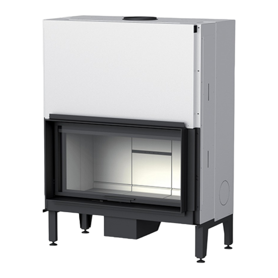
Summary of Contents for MCZ PLASMA 75 WOOD
- Page 1 INSTALLATION GUIDE CLOSED FIREPLACE PLASMA 75/85/95/115 WOOD PLASMA 95B/115B WOOD PLASMA 75/85/95/115 WOOD NATURAL PLASMA 95B/115B WOOD NATURAL Instructions in English...
-
Page 2: Table Of Contents
TABLE OF CONTENTS TABLE OF CONTENTS ....................II INTRODUCTION ......................1 1-WARNINGS AND WARRANTY CONDITIONS ..............2 2-INSTALLATION ......................7 3-FLUE ........................8 4-DIMENSIONS AND TECHNICAL FEATURES ..............16 5-UNPACKING ......................26 6-POSITIONING ......................28 7-OPERATING MODE ....................31 8-AIR INLETS ......................32 9-CHOICE OF FUEL .....................39 10-OPERATION ......................41 11-EASY GOING ......................45 12-EASY SWITCH .......................47 13-ACCESSORIES .......................52... -
Page 3: Introduction
REVISIONS TO THE PUBLICATION The content of this manual is strictly technical and the property of MCZ Group Spa. No part of this manual may be translated into other languages, adapted or reproduced, even in part, in other mechanical or electronic forms, photocopies, recordings or other, without the prior written authorisation from MCZ Group Spa. -
Page 4: 1-Warnings And Warranty Conditions
1-WARNINGS AND WARRANTY CONDITIONS SAFETY PRECAUTIONS • Installation, electrical connection, operating test and maintenance must only be carried out by authorised and qualified personnel. • Install the product in accordance with all local and national legislation and regulations in force in the region or state. • Only use the fuel recommended by the manufacturer. - Page 5 1-WARNINGS AND WARRANTY CONDITIONS • Many of the surfaces of the product get very hot (door, handle, glass, smoke outlet pipes, etc.). Avoid coming into contact with these parts, without adequate protective clothing or suitable implements, such as gloves with thermal protection or “cold handle” operating systems. • It is forbidden to operate the product with the door open or the glass broken.
- Page 6 1-WARNINGS AND WARRANTY CONDITIONS INFORMATION: Please contact the retailer or qualified personnel authorised by the company to resolve a problem. • You must only use the fuel specified by the manufacturer. • When the product is switched on for the first time it is normal for it to emit smoke due to the paint heating for the first time. Therefore make sure the room in which it is installed is well ventilated.
- Page 7 1-WARNINGS AND WARRANTY CONDITIONS EXCLUSIONS The warranty does not cover malfunctions and/or damage to the appliance that arise due to the following causes: • Damage caused during transportation and/or handling • all parts that develop faults due to negligence or improper use, incorrect maintenance, installation that does not comply with the manufacturer’s instructions (always refer to the installation guide provided with the appliance) • incorrect sizing with regard to the use or faults in the installation or failure to adopt the necessary devices to guarantee proper execution...
- Page 8 1-WARNINGS AND WARRANTY CONDITIONS SPARE PARTS In the event of a malfunction, consult the retailer who will forward the call to the Technical Assistance Department. Only use original spare parts. The retailer or service centre can provide all necessary information regarding spare parts. We do not recommend waiting for the parts to get worn out before having them replaced.
-
Page 9: 2-Installation
2-INSTALLATION INSTALLATION FOREWORD The installation position must be chosen according to the room, smoke extraction system and flue. Check with local authorities whether there are any restrictive regulations in force regarding the combustion air inlet, the smoke outlet system, the flue or the chimneypot. The manufacturer declines all responsibility in the event of installations that do not comply with the laws in force, incorrect room air exchange, electrical connection non-compliant with the standards and inappropriate use of the appliance. -
Page 10: 3-Flue
3-FLUE FLUE FOREWORD This Flue chapter has been drawn up with reference to the provisions of European regulations (EN13384 - EN1443 - EN1856 - EN1457). The chapter provides indications for installing an efficient and correct flue but is under no circumstances to substitute the regulations in force, which the qualified technician must be in possession of. - Page 11 3-FLUE TECHNICAL CHARACTERISTICS Have the efficiency of the flue checked by an authorised technician. The flue must be sealed against flue gasses, in a vertical direction without narrowing, be made with materials impermeable to smoke, condensation, thermally insulated and suitable to resist normal mechanical stress over time (we recommend fireplaces made of A/316 or refractory material with insulated round section double chamber).
- Page 12 3-FLUE ROOF AT 60° ROOF AT 45° 45° 60° A = MIN. 2.60 metres A = MIN. 2.00 metres FIGURE 5 FIGURE 6 B = DISTANCE > 1.20 metres B = DISTANCE > 1.30 metres C = DISTANCE < 1.20 metres C = DISTANCE <...
- Page 13 3-FLUE MAINTENANCE The flue must be kept clean, since the deposit of soot or unburned oils reduces the cross-section reducing the draught, thus compromising the efficient operation of the product and, if large build-ups accumulate, they can catch fire. The flue and chimneypot must be cleaned and checked by a qualified chimney sweep at least once a year.
- Page 14 3-FLUE EXTERNAL AIR INLET It is mandatory to provide an adequate external air inlet that supplies the combustion air required for the product to work properly. The flow of air between the outside and the installation room may be direct, through an inlet in an external wall of the room (preferable solution see Figure 9 c);...
- Page 15 3-FLUE For closed fireplaces installed in studio flats, bedrooms and bathrooms (where allowed), it is mandatory to connect the combustion air to the outside. In particular for sealed products the connection must be sealed in order not to compromise the overall sealed characteristic of the system.
- Page 16 3-FLUE TYPE OF SYSTEM SMOKE DUCT (Smoke connection) Minimum vertical length 1.5 metres Maximum length 4.5 metres (with 1 a 45° bend max) Use smoke ducts that are able to withstand the unit operating temperatures (min. T400). The use of flexible metal hoses made of fibre cement or aluminium is forbidden.
- Page 17 3-FLUE EXAMPLES OF CORRECT INSTALLATION 1. Installation of Ø200mm flue with hole for the passage of the pipe increased by: minimum 100mm around the pipe if next to non flammable parts such as cement, brick, etc.; or minimum 400mm around the pipe (or as required by data tags) if next to flammable parts such as wood etc.
-
Page 18: 4-Dimensions And Technical Features
4-DIMENSIONS AND TECHNICAL FEATURES PLASMA 75 WOOD DIMENSIONS Ø150 693* Ø200 Ø100-150 Ø100-150 *FIREBOX OPENING FOR CLADDING *APERTURA FOCOLARE PER RIVESTIMENTO NATURAL VENTILATION KNOCKOUT HOLE SEMITRANCIO VENTILAZIONE NATURALE KNOCKOUT HOLES Ø 100-150 SEMITRANCI Ø100-150 INGRESSO ARIA COMBURENTE Ø 150 COMBUSTION AIR INLET Ø 150... - Page 19 4-DIMENSIONS AND TECHNICAL FEATURES PLASMA 75 WOOD DIMENSIONS NATURAL Ø150 693* Ø200 *FIREBOX OPENING FOR CLADDING *APERTURA FOCOLARE PER RIVESTIMENTO INGRESSO ARIA COMBURENTE Ø 150 COMBUSTION AIR INLET Ø 150 Technical Dept. - All rights reserved - Reproduction prohibited...
- Page 20 4-DIMENSIONS AND TECHNICAL FEATURES PLASMA 85 WOOD DIMENSIONS 803* Ø150 Ø200 Ø100-150 Ø100-150 *FIREBOX OPENING FOR CLADDING *APERTURA FOCOLARE PER RIVESTIMENTO NATURAL VENTILATION KNOCKOUT HOLE SEMITRANCIO VENTILAZIONE NATURALE KNOCKOUT HOLES Ø 100-150 SEMITRANCI Ø100-150 INGRESSO ARIA COMBURENTE Ø 150 COMBUSTION AIR INLET Ø 150...
- Page 21 4-DIMENSIONS AND TECHNICAL FEATURES PLASMA 85 WOOD DIMENSIONS NATURAL Ø150 803* Ø200 *FIREBOX OPENING FOR CLADDING *APERTURA FOCOLARE PER RIVESTIMENTO INGRESSO ARIA COMBURENTE Ø 150 COMBUSTION AIR INLET Ø 150 Technical Dept. - All rights reserved - Reproduction prohibited...
- Page 22 4-DIMENSIONS AND TECHNICAL FEATURES PLASMA 95 WOOD DIMENSIONS 1056 903* Ø150 Ø200 Ø100-150 Ø100-150 *FIREBOX OPENING FOR CLADDING *APERTURA FOCOLARE PER RIVESTIMENTO NATURAL VENTILATION KNOCKOUT HOLE SEMITRANCIO VENTILAZIONE NATURALE (VN) SEMITRANCI Ø100-150 KNOCKOUT HOLES Ø 100-150 INGRESSO ARIA COMBURENTE Ø 150 COMBUSTION AIR INLET Ø...
- Page 23 4-DIMENSIONS AND TECHNICAL FEATURES PLASMA 95 WOOD DIMENSION NATURAL 1056 Ø150 903* Ø200 *FIREBOX OPENING FOR CLADDING *APERTURA FOCOLARE PER RIVESTIMENTO INGRESSO ARIA COMBURENTE Ø 150 COMBUSTION AIR INLET Ø 150 Technical Dept. - All rights reserved - Reproduction prohibited...
- Page 24 4-DIMENSIONS AND TECHNICAL FEATURES PLASMA 115 WOOD DIMENSION 1276 Ø150 1123* Ø200 Ø100-150 Ø100-150 *FIREBOX OPENING FOR CLADDING *APERTURA FOCOLARE PER RIVESTIMENTO NATURAL VENTILATION KNOCKOUT HOLE SEMITRANCIO VENTILAZIONE NATURALE KNOCKOUT HOLES Ø 100-150 SEMITRANCI Ø100-150 INGRESSO ARIA COMBURENTE Ø 150 COMBUSTION AIR INLET Ø...
- Page 25 4-DIMENSIONS AND TECHNICAL FEATURES PLASMA 115 WOOD DIMENSION NATURAL 1276 Ø150 1123* Ø200 *FIREBOX OPENING FOR CLADDING *APERTURA FOCOLARE PER RIVESTIMENTO COMBUSTION AIR INLET Ø 150 INGRESSO ARIA COMBURENTE Ø 150 Technical Dept. - All rights reserved - Reproduction prohibited...
- Page 26 4-DIMENSIONS AND TECHNICAL FEATURES PLASMA 95B WOOD DIMENSION 1056 903* Ø200 Ø200 Ø100-150 Ø100-150 1056 *FIREBOX OPENING FOR CLADDING *APERTURA FOCOLARE PER RIVESTIMENTO KNOCKOUT HOLES Ø 100-150 SEMITRANCI Ø100-150 INGRESSO ARIA COMBURENTE Ø 150 COMBUSTION AIR INLET Ø 150...
- Page 27 4-DIMENSIONS AND TECHNICAL FEATURES PLASMA 95B WOOD DIMENSION NATURAL 1056 903* Ø150 Ø200 *FIREBOX OPENING FOR CLADDING *APERTURA FOCOLARE PER RIVESTIMENTO INGRESSO ARIA COMBURENTE Ø 150 COMBUSTION AIR INLET Ø 150 Technical Dept. - All rights reserved - Reproduction prohibited...
- Page 28 4-DIMENSIONS AND TECHNICAL FEATURES PLASMA 115B WOOD DIMENSION 1276 1123* Ø150 Ø200 Ø100-150 Ø100-150 1276 *FIREBOX OPENING FOR CLADDING *APERTURA FOCOLARE PER RIVESTIMENTO SEMITRANCI Ø100-150 KNOCKOUT HOLES Ø 100-150 INGRESSO ARIA COMBURENTE Ø 150 COMBUSTION AIR INLET Ø 150...
- Page 29 4-DIMENSIONS AND TECHNICAL FEATURES PLASMA 115B WOOD DIMENSION NATURAL 1276 1123* Ø150 Ø200 *FIREBOX OPENING FOR CLADDING *APERTURA FOCOLARE PER RIVESTIMENTO COMBUSTION AIR INLET Ø 150 INGRESSO ARIA COMBURENTE Ø 150 Technical Dept. - All rights reserved - Reproduction prohibited...
- Page 30 4-DIMENSIONS AND TECHNICAL FEATURES TECHNICAL CHARACTERISTICS PLASMA 75 WOOD PLASMA 85 WOOD PLASMA 75 WOOD NATURAL PLASMA 85 WOOD NATURAL Energy Efficiency Class Type of fuel Wood Wood Hourly consumption 3.7 kg/h - 1.7 kg/h 3.9 kg/h - 1.9 kg/h Reloading/load time 40 min / 2.5 kg...
- Page 31 4-DIMENSIONS AND TECHNICAL FEATURES TECHNICAL CHARACTERISTICS PLASMA 95 WOOD PLASMA 115 WOOD PLASMA 95 WOOD NATURAL PLASMA 115 WOOD NATURAL Energy Efficiency Class Type of fuel Wood Wood Hourly consumption 3.9 kg/h - 1.9 kg/h 4.1 kg/h* – 2.0 kg/h Reloading/load time 41 min / 2.7 kg 41 min / 2.8 kg...
- Page 32 4-DIMENSIONS AND TECHNICAL FEATURES TECHNICAL CHARACTERISTICS PLASMA 95B WOOD PLASMA 115B WOOD PLASMA 95B WOOD NATURAL PLASMA 115B WOOD NATURAL Energy Efficiency Class Type of fuel Wood Wood Hourly consumption 3,9 kg/h 3,8 kg/h Reloading/load time 41 min / 2,7 kg 40 min / 2,5 kg Nominal output power: kW 12,9 (Kcal/h 11094)
-
Page 33: 5-Unpacking
5-UNPACKING IMPORTANT! The closed fireplace must be installed and connected to the smoke duct exclusively by a specialised technician, so that every local or national regulation is observed. Installation must nevertheless be carried out in accordance with regulation UNI 10683. When you unwrap the closed fireplace, make sure that every part is in perfect working order or check for any damage due to transport. - Page 34 5-UNPACKING RELEASING THE COUNTERWEIGHTS The closed fireplace is delivered with the sliding counterweights locked to avoid dangerous counterblows during transport and positioning, which could damage the parts involved in sliding as well as the door and the glass-ceramic. To release the counterweights and therefore the door, remove the screws as shown in the figure below from both sides of the closed fireplace where the arrows stickers are positioned on both sides.
-
Page 35: 6-Positioning
6-POSITIONING POSITIONING The PLASMA closed fireplace can be positioned in a corner or against the wall. It can be customised with the cladding of the manufacturing company or built at the time of installation with heat-resistant materials. Closed fireplaces are freestanding monoblocks that simplify installation and do not require any integrative support. Closed fireplaces are fitted with particular anchoring points to facilitate handling (handling kit - not provided - see chapter on accessories) and a lifting hook (weight approximately 300/400 kg depending on the model). - Page 36 6-POSITIONING Attention!! All measurements pertaining to positioning are provided in chapter 4 in the technical data table. dR = distance from flammable material - back dL = distance from flammable material - side radiation dS = distance from flammable material - side dC = minimum distance from ceiling dB = distance from flammable material - underneath K =safety distance for radiation...
- Page 37 6-POSITIONING HEIGHT ADJUSTMENT AND LEVELLING The Plasma closed fireplace is supplied with adjustable feet which have the purpose of levelling the hearth of the closed fireplace, and have a range of about 3 cm. Anyone wishing to raise the closed fireplace by more than 3 cm will need to create a brick pedestal to set the product on. In any case do not remove the feet which are essential for levelling.
-
Page 38: 7-Operating Mode
7-OPERATING MODE OPERATING MODE SELECTION IMPORTANT! Before installation it is necessary to decide what system needs to be implemented. The closed fireplace has the possibility of distributing hot air in NATURAL CONVECTION (COMFORT AIR VN) mode or FORCED CONVECTION (COMFORT AIR VF) mode through the use of a forced ventilation kit. IMPORTANT! With both systems the installer is required to take down the knockout holes set up above the closed fireplace to facilitate thermal exchange and air circulation. -
Page 39: 8-Air Inlets
8-AIR INLETS EXTERNAL AND INTERNAL AIR INLET COMBUSTION AIR INLET The closed fireplace has a hole with a diameter of 150 mm for the intake of the air required for combustion. Use a hose to connect the air intake hole to the exterior of the cladding and connect it to a grid so that the route is separate from the natural or forced convection air. - Page 40 8-AIR INLETS Please bear in mind that: • All external air inlets must have a closing damper that can be controlled from the outside, along with an insect screen. • The air inlet section is a net value, so you need to consider the area of any other elements (netting, etc.) • Periodically clean the filters or netting to ensure the air can pass through • Do not, for any reason, obstruct the air inlets if the closed fireplace or ventilation kit is running.
- Page 41 8-AIR INLETS WOODEN BEAM INSULATION The wooden beam must be protected with adequate insulation from hot parts in order to prevent the risk of fire or damage to the cladding. THERMAL PROTECTION OF THE BEAM (CONSTRUCTION EXAMPLES) MARBLE SPANDREL, OR OTHER NON-FLAMMABLE MATERIAL WOODEN BEAM INSULATION TO BE APPLIED DEFLECTOR IN NON-FLAMMABLE MATERIAL...
- Page 42 8-AIR INLETS HOOD VENTILATION OUTLETS Both in the case of installation with natural ventilation and if using the Comfort Air kit for forced ventilation, it is mandatory to install the manufacturer’s hood ventilation vents or vents that can guarantee the same kind of operation and the same air passage section.
- Page 43 8-AIR INLETS NATURAL CONNECTION (without casing) Combustion air The combustion air inlet “C” Ø 150 provided on the Plasma closed fireplace must be connected to the exterior of the cladding by a pipe with 150 mm diameter and a maximum length of 3 metres. Smoke outlet Smoke outlet “D”...
- Page 44 8-AIR INLETS NATURAL VENTILATION CONNECTION Combustion air The combustion air inlet “C” Ø 150 provided on the Plasma closed fireplace must be connected to the exterior of the cladding by a pipe with 150 mm diameter and a maximum length of 3 metres. Smoke outlet Smoke outlet “D”...
- Page 45 8-AIR INLETS VENTILATION CONNECTION COMFORT AIR BASIC Combustion air The combustion air inlet “C” Ø 150 provided on the Plasma closed fireplace must be connected to the exterior of the cladding by a pipe with 150 mm diameter and a maximum length of 3 metres. Smoke outlet Smoke outlet “D”...
-
Page 46: 9-Choice Of Fuel
9-CHOICE OF FUEL The instructions in this chapter refer explicitly to the Italian installation regulation UNI 10683. In any case, always observe the regulations in force in the country of installation. FUEL Below are some useful instructions for the correct use of the product • Only burn natural, untreated wood with maximum moisture content of 20%, which corresponds to cut wood with 2 years of correct drying • All types of wood are suitable, both hard and soft: beech, maple, oak, birch, acacia, fir, pine, larch, etc. - Page 47 9-CHOICE OF FUEL FUEL: Wood FUEL: Wood In order to achieve maximum efficiency from your product, it is of utmost importance to use wood with suitable characteristics. In order to achieve maximum efficiency from your product, it is of utmost importance to use wood with suitable characteristics. We recommend using heating wood such as oak-beech-ash-robinia-common oak or non-resinous pressed wood logs.
-
Page 48: 10-Operation
10-OPERATION PRECAUTIONS BEFORE START-UP Make sure you have read and fully understood the contents of this instruction manual. Remove all components that could burn from the firebox and door (instructions and various adhesive labels). Remove the stickers from the ceramic glass otherwise the high temperature could melt them and cause irreparable damage to the glass. The product can be positioned at in a corner or along a wall. - Page 49 10-OPERATION by the presence of an oily film and excess paint, which will go away after lighting the fire a few times. • Do not close the rise and fall door right away, rather, leave it open by about 10 cm so that the wood can burn better and any moisture contained in it can dry.
- Page 50 10-OPERATION FIRST START-UP NOTE REGARDING PAINT EXHALATION It is recommended to air the room the first time the stove is switched on, to evacuate any smells and/or fumes emitted by the paint during the drying and hardening stage due to the heat. Do not stand close to the stove and as mentioned, air the room.
- Page 51 10-OPERATION The photo on the side on the side logs illustrates a tack of lighted from the wood lighted from the bottom with dry top with dry wood. wood This is the This is the most correct most common and clean way of method but not starting the fire.
-
Page 52: 11-Easy Going
11-EASY GOING COMBUSTION CONTROL The new “Easy Going” air adjustment system is based on the choice of 5 types of use of the closed firebox. PRIMARY AIR The primary air comes in directly through the openings between the casing and the structure of the closed fireplace. This air makes combustion possible. - Page 53 11-EASY GOING SECONDARY AIR The adjustment needs to be made using the same lever as the primary air. The secondary air comes out proportionately to the primary air in a pre-calculated balance that the user can never modify, risking poor adjustments. Accordingly there will never be excessive combustion. Secondary air allows the completion of combustion and increases the efficiency.
-
Page 54: 12-Easy Switch
12-EASY SWITCH DOOR OPENING SYSTEM The “Easy Switch” guarantees the possibility of using either the handle or a “hands cool” element. The door of the closed fireplace can be opened using the handle or without the handle and therefore with the cold handle. With the handle: • grip handle “M”... - Page 55 12-EASY SWITCH For opening without a handle, follow the points below in the stated order; an incorrect manoeuvre could cause parts of the closed fireplace to break: • raise door “P” with handle “M” • take out the two screws “o” that secure the handle “M” • take off handle “M”...
- Page 56 12-EASY SWITCH • lower door “P” Attention! Once the handle is off to lower and raise the door you need to use the cold handle “H”, provided. • pull the top hook “y” towards you 45°...
- Page 57 12-EASY SWITCH • lower door “P” to an inclination of approximately 45° (the position stopped by the retainers) • take out the two internal screws “v” and bracket “S” on both the right and left of the door Technical Dept. - All rights reserved - Reproduction prohibited...
- Page 58 DOOR OPENING SWITCH On closed fireplaces there is a switch installed by MCZ and in the case of forced ventilation, it turns off the fans when the door of the closed fireplace is open (see the relative manual for the basic-slim comfort air kit).
-
Page 59: 13-Accessories
13-ACCESSORIES ACCESSORIES PASSE-PARTOUT Passe-partout “F” is used for installations without cladding. It is attached to the structure by six screws “x”. All of the relative instructions are inside the kit. Installation on front fireplaces. WALL PARETE Installation on dual-front fireplaces. WALL PARETE Technical Dept. - Page 60 SPACER Spacer “G” is supplied to compensate for the hole between the closed fireplace and the craft cladding. MCZ claddings already compensate for this hole. It is attached to the structure by four screws “x”. All of the relative instructions are inside the kit.
- Page 61 13-ACCESSORIES HANDLING KIT The handling kit is supplied to simplify closed fireplace transport operations. The kit is composed of four handling units “R”, and four chimney holding bars “B”. The bars “B” need to be inserted into the relative holes on the sides of the closed fireplaces, while the handling units need to be attached to the legs of the closed fireplace by the relative screws “v”.
-
Page 62: 14-Maintenance And Cleaning
14-MAINTENANCE AND CLEANING ATTENTION! All cleaning operations of all parts need to be carried out when the closed fireplace is completely cold; make sure that the ashes are out, use personal protective equipment and use appropriate maintenance equipment. CLEANING UNDER THE USER’S RESPONSIBILITY CLEANING THE GLASS To clean the glass, use specific products (see our price list) or a cloth dipped in water and ammonia solution or a little white ash and a sheet of newspaper. - Page 63 14-MAINTENANCE AND CLEANING ASH REMOVAL We recommend cleaning the hearth suitably for correct combustion. Use a metal pan and a brush to remove the ash from the hearth and place the ash non-flammable containers for transport. Hot ashes must not be stored outside unsupervised or thrown into the rubbish bin. Allow them to cool down in the open air in a metal container.
- Page 64 MCZ GROUP S.p.A. Via La Croce n°8 33074 Vigonovo di Fontanafredda (PN) – ITALY Telephone: 0434/599599 a.s. Fax: 0434/599598 Internet: www.mcz.it e-mail: mcz@mcz.it 8901711000 REV.5 31/05/2018...
Need help?
Do you have a question about the PLASMA 75 WOOD and is the answer not in the manual?
Questions and answers