MCZ VIVO 80 Manual
Pellet hydro
Hide thumbs
Also See for VIVO 80:
- Use and installation manual (57 pages) ,
- Installation manual (75 pages)

Related Manuals for MCZ VIVO 80


Summary of Contents for MCZ VIVO 80
- Page 1 INSTALLATION GUIDE INSERT INSERTO VIVO 80 VIVO 80 PELLET PELLET HYDRO HYDRO Translation of the original instructions...
-
Page 2: Table Of Contents
TABLE OF CONTENTS INTRODUCTION ......................1 1-WARNINGS AND WARRANTY CONDITIONS ..............2 2-INSTALLATION INSTRUCTIONS ..................5 3-INSTALLATION AND ASSEMBLY ..................13 4-OPERATION ......................25 5-SAFETY DEVICES AND ALARMS ...................47 6-MAINTENANCE AND CLEANING ..................51 7-PROBLEMS/CAUSES/SOLUTIONS ................56 8-WIRING DIAGRAMS ....................60... -
Page 3: Introduction
No part of this manual can be translated into another language and/or altered and/or reproduced, even partially, in another form, by mechanical or electronic means, photocopied, recorded or similar, without prior written approval from MCZ Group Spa. The company reserves the right to make changes to the product at any time without prior notice. The proprietary company reserves its rights according to the law. -
Page 4: 1-Warnings And Warranty Conditions
1-WARNINGS AND WARRANTY CONDITIONS SAFETY PRECAUTIONS • Installation, electrical connection, functional verification and maintenance must only be performed by qualified or authorised personnel. Install the product in accordance with all the local and national laws and Standards applicable in the relative place, •... - Page 5 1-WARNINGS AND WARRANTY CONDITIONS 1-AVVERTENZE E CONDIZIONI DI GARANZIA INFORMATION: Please contact the retailer or qualified personnel authorised by the company to resolve a problem. • only fuel stipulated by the company must be used. • Check and clean the smoke outlet pipes regularly (connection with the product). •...
- Page 6 1-WARNINGS AND WARRANTY CONDITIONS INTERVENTION REQUEST The company declines all liability if the product and any other accessory is used incorrectly or altered without authorisation. All parts must be replaced with original spare parts. The request must be sent to the retailer who will forward it to the Technical Assistance Service. SPARE PARTS Only use original spare parts.
-
Page 7: 2-Installation Instructions
2-INSTALLATION INSTRUCTIONS The requirements in this chapter refer to the regulations of the Italian installation Standard UNI 10683. In any case, always comply with the regulations in force in the country of installation PELLETS Wood pellets are manufactured by hot-extruding compressed sawdust which is produced during the processing of natural dried wood (without paints). - Page 8 2-INSTALLATION INSTRUCTIONS PRECAUTIONS REGARDING INSTALLATION IMPORTANT! Product installation and assembly must be carried out by qualified personnel. The product must be installed in a suitable place for it to be regularly opened and routine maintenance to be performed. The site must be: •...
- Page 9 • where another heating appliance is installed without an independent air flow. It is forbidden to place the product in an explosive atmosphere. MINIMUM DISTANCES VIVO 80 PELLET HYDRO Non-flammable walls Flammable walls A = 50 mm A = 100 mm...
- Page 10 2-INSTALLATION INSTRUCTIONS CONNECTION OF THE SMOKE EXHAUST DUCT When making the hole for the passage of the smoke discharge pipe, one must take into account the possible presence of flammable materials. If the hole must be made through a wooden wall or thermolabile material, the INSTALLER MUST first of all use the appropriate wall fitting (minimum diameter 13 cm) and suitably insulate the pipe of the product that passes through it using adequate insulating materials (1.3 - 5 cm thick with minimum thermal conductivity 0.07 W/m°K).
- Page 11 2-INSTALLATION INSTRUCTIONS Always use pipes and fittings with appropriate seals that guarantee tightness. It must be possible to inspect all sections of the flue duct and they must be removable for periodic internal cleaning (T-fitting with inspection hole). Position the product considering all the above requirements and instructions. IMPORTANT! The following conditions must be complied with when connecting the appliance to the chimney: •...
- Page 12 2-INSTALLATION INSTRUCTIONS CONNECTION TO THE EXTERNAL AIR INLET It is essential for the room where the product is installed to be adequately ventilated in order to guarantee sufficient air for proper combustion in the appliance. This is possible by means of suitable ventilation openings in the room itself or in an interconnected room through a permanent opening between the rooms.
- Page 13 2-INSTALLATION INSTRUCTIONS CONNECTIONS CONNECTION TO THE CHIMNEY CONNECTION TO AN EXTERNAL DUCT CONNECTION TO THE CHIMNEY WITH AN INSULATED OR DOUBLE-WALL PIPE The chimney's internal dimensions must The minimum internal dimensions of the The connection between the product and not exceed 20x20 cm or 20 cm diameter; external duct must be 10x10 cm or 10 cm the chimney or the smoke duct must not in the event of bigger sizes or bad chimney...
- Page 14 2-ISTRUZIONI PER L'INSTALLAZIONE 2-INSTALLATION INSTRUCTIONS TING PROBLEMS RELATED TO DRAUGHT DEFECTS IN THE CHIMNEY Among all the weather and geographical conditions that affect chimney operation (rain, fog, snow, altitude a.s.l., exposure to sunlight, orientation to the cardinal points, etc.), the wind is certainly the most determinant. In fact, besides the thermal depression caused by the difference in temperature between inside and outside the chimney, there is another type of depression (or overpressure): dynamic pressure caused by the wind.
- Page 15 3-INSTALLAZIONE E MONTAGGIO 3-INSTALLATION AND ASSEMBLY DRAWINGS AND CHARACTERISTICS VIVO 80 PELLET HYDRO DIMENSIONS (dimensions in mm) 786.5 53.5 87.8 Technical Dept. - All rights reserved - Reproduction is prohibited...
-
Page 16: 3-Installation And Assembly
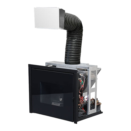
3-INSTALLATION AND ASSEMBLY TECHNICAL CHARACTERISTICS VIVO 80 PELLET HYDRO 16.9 kW (14534 kcal/h) Nominal output power: 14.2 kw (12212 kcal/h) - H 4.9 kW (4214 kcal/h) Global heat output Min: 3.5 kw (3010 kcal/h) - H Efficiency at Max 90,1%... - Page 17 3-INSTALLATION AND ASSEMBLY PREPARATION AND UNPACKING The product is supplied in a single package. Inside the package there are the tube, the loading door, the frame and ventilation grilles. Open the package, remove the product from the pallet and set it in the pre-selected place, making sure this complies with the requirements. PRODUCT PACKAGING The two brackets must be removed in order to remove the product from pallet, by loosening the two flanged nuts and the two screws.
- Page 18 3-INSTALLATION AND ASSEMBLY POSITIONING Before installing the product assess the optimal position. One can install the product in a pre-existing traditional fireplace or as a new system. In addition to lift the product to the recommended height of 600 mm one can purchase a metal support separately (refer to the relative optional accessories price list) INSTALLATION IN A PRE-EXISTING FIREPLACE Assess the following elements:...
- Page 19 3-INSTALLATION AND ASSEMBLY FASTENING TO THE BASE OF THE INSERT It is mandatory to anchor the product to a support as the authorised technician can remove the combustion chamber from its seat by means of two extendable guides while performing the annual maintenance. Fasten the insert as follows: •...
- Page 20 Another decision to be made before positioning the product is to define the side on which to install the chute for loading fuel. The pel- lets fuelled Vivo 80 Hydro is delivered with two clamps, the connection pipe and chute with hatch.
- Page 21 3-INSTALLATION AND ASSEMBLY HOOD VENTILATION GRILLES Foreword Depending on how the product is positioned, one must provide grilles for ventilation. If inserted in existing cladding, the ventilation grilles on the cladding will be used. If used as a new installation, the company recommends installing the ventilation grilles as described in the following paragraph. CONVECTION HOT AIR HOT AIR INFLOW FROM THE ROOM HOOD VENTILATION GRILLES FOR NEW CLADDING...
- Page 22 3-INSTALLATION AND ASSEMBLY ELECTRICAL CONNECTION First connect the power cable to the rear part of the product and then to a wall socket, which must always be accessible. Should this not be possible, during installation, insert appropriate power supply disconnection devices, in compliance with the national regulations regarding electrical installations.
- Page 23 3-INSTALLATION AND ASSEMBLY WOODEN BEAM INSULATION If you wish to mount a wooden beam, it must be protected with adequate insulation from the hot parts in order to prevent the risk of fire or damage to the cladding. 1 - INSULATION APPLIED OR TO BE APPLIED 2 - WOODEN BEAM 3 - MARBLE OR OTHER MATERIAL STANDARD CLADDING ASSEMBLY The installation guide found in each specific cladding must be referred to for the assembly of MCZ product specific claddings.
- Page 24 3-INSTALLATION AND ASSEMBLY DIAGRAM FOR MAKING HOLES IN THE CLADDING PELLET LOADING DOOR INSERTION HOLE The product can be installed on a brick base built on site or one can purchase the support (optional) that enables to raise the product to a suitable height.
- Page 25 3-INSTALLATION AND ASSEMBLY PRODUCT INLET HOLE The hole to be made in the wall must be 765*610 mm. These measurements allow the frame to cover the gap that remains between the product and the hole and also allow the product to be removed if maintenance is to be performed and/or parts are to be replaced. SWITCH AND CONTROL PANEL CONNECTION The emergency panel and switch are already fitted on the pellets loading door and are already connected to the relative cables by the manufacturer.
- Page 26 3-INSTALLATION AND ASSEMBLY PELLETS DOOR OPENING/CLOSING The door is fitted with a pressure closure and is therefore completely free of handles or grips. To open or close the door, press the upper left corner. With a simple press this will hook on or unhook from the closure latch placed on the door frame.
-
Page 27: 4-Operation
4-OPERATION BEFORE START-UP GENERAL PRECAUTIONS Remove all components that could burn from the firebox and glass (instructions, various adhesive labels and any polystyrene). Check that the brazier is positioned correctly and rests properly on the base. After a long period of inactivity, remove any pellets left in the hopper (using a vacuum cleaner with a long pipe ), as they could have absorbed moisture, thereby altering their original characteristics and no longer being suitable for combustion. - Page 28 4-OPERATION It is extremely important to make sure the product is not immediately overheated and the temperature is increased gradually, initially using low power. This will prevent damaging the welds and the steel structure. DO NOT EXPECT HEATING EFFICIENCY IMMEDIATELY!!! LOADING THE PELLETS Fuel loading is achieved via the lateral or frontal door to be fitted on the cladding, which enables access to the fuel loading chute.
- Page 29 4-OPERATION PLUMBING CONNECTION IMPORTANT! The connection of the stove to the plumbing system must be carried out ONLY by specialised personnel capable of carrying out state of the art installation, in compliance with the standards in force in the country of installation. The company will not be held responsible for damage to persons or things in the event of failed operation if the aforementioned warning is not complied with CONNECTION DIAGRAM...
- Page 30 4-OPERATION SYSTEM CONNECTIONS Make the connections to the corresponding fittings shown in the diagram above. Make sure the pipes are not placed under tension or undersized. If installation of the product involves interaction with another, pre-existing system complete with heating equipment (gas boiler, methane boiler, diesel boiler, etc.), call in qualified personnel, who subsequently will be responsible for conformity of the system in compliance with the applicable law in force.
- Page 31 4-OPERATION SYSTEM FILLING To load the heating system use the predisposed loading tap in the main boiler. During this operation, any air in the system is released via the air valve located in the upper part of the product. To allow the valve to release air it is recommended to loosen the screw on the valve itself (see figure). The filling pressure of the system WHEN COLD must be 1 bar.
- Page 32 4-OPERATION WATER CHARACTERISTICS The characteristics of the water used to fill the system are very important to prevent the build-up of mineral salts and the formation of incrustations along the pipes, in the boiler and in the heat exchangers. Therefore, please ASK YOUR PLUMBER FOR HIS ADVICE CONCERNING: •...
- Page 33 4-OPERATION INSTALLATION DIAGRAM FOR HEATING WITHOUT DOMESTIC WATER KIT This diagram is purely a guideline and therefore has no project value. Technical Dept. - All rights reserved - Reproduction is prohibited...
- Page 34 4-OPERATION INSTALLATION DIAGRAM FOR HEATING COMBINED WITH A BOILER This diagram is purely a guideline and therefore has no project value...
- Page 35 4-OPERATION INSTALLATION DIAGRAM COMBINED WITH A STORAGE TANK This diagram is purely a guideline and therefore has no project value. Technical Dept. - All rights reserved - Reproduction is prohibited...
- Page 36 4-OPERATION It is good practice to guarantee effective ventilation in the room during the initial start-up, as the product will emit some smoke and smell of paint. Do not stand close to the product and air the room. The smoke and smell of paint will disappear after about an hour of operation, however, remember they are not harmful in any case.
- Page 37 4-OPERATION CONTROL PANEL LOGIC Some useful information is provided below to understand the logic and use of the control panel: • The control panel backlight switches off after about 30" seconds of keypad inactivity. To switch the backlight on again simply press any of the panel buttons.
- Page 38 4-OPERATION SETTING THE CURRENT TIME AND DATE By pressing the MENU key SET will appear. Enter SET to change: hour minutes day number month year For example if we need to change the time, when HOUR appears on the display press SET, the hour will start to flash in the centre of the display, then with the keys at the bottom on the left or right change the hour and then the minutes, day, etc.
- Page 39 4-OPERATION SETTING THE LANGUAGE Press the MENU key then scroll with the keys at the bottom on the right or left until SETTINGS appears, press SET and LANGUAGE will appear, press SET again and set the chosen language. By convention the days of the week are indicated with abbreviations deriving from the language set on the panel. In the case of English: Monday Thursday Sunday...
- Page 40 4-OPERATION The default temperature is 65°C and it can not be set below 50°C or above 80°C. To adjust it: press any button; press the "menu" button, via the scrolling buttons display the “SET TEMP.H2O” screen; press the “SET” button; set the desired temperature via the “<>”...
- Page 41 4-OPERATION AUTOMATIC MODE WITH AUTO-ECO This mode changes the behaviour of the product in automatic mode: upon reaching the temperature set by the user, the product modulates at power 1 for a short period of time and then, if the temperature remains constant and higher than that set, it switches off. The appliance switches back on automatically only when the room/water require heat again (not before an interval necessary for the product to cool down).
- Page 42 4-OPERATION To explain SLEEP function simply, one can say that it allows to switch off the product starting from a minimum of + 10 minutes compared to the hour displayed and to a maximum of 23.50 hours. To set the function press Menu with the key at the top on the right then Date and Time appears on the screen, then scroll with the key at the bottom on the right until Sleep appears, confirm with the Set key.
- Page 43 4-OPERATION CHRONO FUNCTION This function mode allows to programme start-up and shutdown of the product automatically. Usually stoves have the CHRONO mode deactivated. The basic settings of the CHRONO mode are: • Choice of start-up/shutdown times • Choice of day of programme activation Setting the current day and time is essential for the proper operation of the chrono function.
- Page 44 4-OPERATION SETTING A CUSTOMISED PROGRAMME The selectable daily programmes are 62 and one can choose a different program for every day of the week. To activate this option proceed as described above to set a weekly programme, only that instead of selecting one of the programs contained in the weekly programmes table (from P01 to P10) select the USER programme.
- Page 45 4-OPERATION PRE-SET WEEKLY AND DAILY PROGRAMMES WEEKLY PROGRAMMES The weekly programmes chosen by the manufacturer and memorised within the product control panel have been designed to meet the requirements of most users who leave their home during working hours (labourers, shopkeepers, employees, shift workers, etc..) as well as those who stay at home for most of the day (housewives, elderly people, etc..).
- Page 46 4-OPERATION DAILY PROGRAMS Daily Hourly timetable programs...
- Page 47 4-OPERATION Daily Hourly timetable programs Technical Dept. - All rights reserved - Reproduction is prohibited...
- Page 48 5-PANNELLO DI EMERGENZA 4-OPERATION PRACTICAL EXAMPLE OF DAILY PROGRAMMING SETTING A DAILY PROGRAM Take for example a user who has not established daily schedules (freelancer, etc..) but who roughly knows that he is in the house the following days at the following times: MONDAY at home until 10:00 and from 17:00 onwards TUESDAY...
-
Page 49: 5-Safety Devices And Alarms
5-SAFETY DEVICES AND ALARMS SAFETY DEVICES The product is supplied with the following safety devices: SMOKE TEMPERATURE PROBE Detects the temperature of the smoke, thereby enabling start-up or stopping the product when the smoke temperature drops below the preset value. PELLET HOPPER TEMPERATURE PROBE If the temperature exceeds the preset safety value, it immediately stops the product, which must cool down before the probe is restored and the product restarted. - Page 50 5-SAFETY DEVICES AND ALARMS ALARM ALERTS If an operating anomaly occurs, the product enters the shutdown phase due to an alarm and informs the user regarding the type of fault by means of a 3 digit code that remains displayed on the emergency panel. The alarm is indicated permanently by the relative three digit code, a flashing red LED that lights up on the emergency panel and an intermittent buzzer for the first 10 minutes.
- Page 51 5-SAFETY DEVICES AND ALARMS The spark plug is faulty. Contact an authorised service centre to have the component replaced. Pellets supply fault. Contact an authorised service centre to have the component replaced. Faulty air flow rate sensor. This alarm does not block the system and only a warning screen is displayed.
- Page 52 5-SAFETY DEVICES AND ALARMS BLOCKED PRODUCT The following may cause the product to be mechanically blocked: • structure overheating (“A03”). • Smoke overheating (“A04”). • During product operation, air that has not been controlled has entered the combustion chamber or the chimney is clogged (“A05”). •...
-
Page 53: 6-Maintenance And Cleaning
6-MAINTENANCE AND CLEANING EXAMPLE OF A CLEAN BRAZIER EXAMPLE OF A DIRTY BRAZIER ATTENTION! All the cleaning operations of all parts must be performed with a completely cold product and the plug disconnected. The insert requires little maintenance if used with certified good quality pellets. DAILY OR WEEKLY CLEANING PERFORMED BY THE USER BEFORE EACH START-UP Clean the ash and any deposits in the brazier that could clog the air passage holes. - Page 54 6-MAINTENANCE AND CLEANING CLEANING THE GLASS It is recommended to clean the ceramic glass with a dry brush, or if it is very dirty, spray a little specific detergent and clean with a cloth. ATTENTION! Do not use abrasive products and do not spray the glass spray cleaner on the painted parts or the door gaskets (ceramic fibre cord).
- Page 55 6-MAINTENANCE AND CLEANING SWAB BRUSH SCRAPER GO OVER WITH SWAB BRUSH FIREBOX WALLS PELLET STOVE BRUSH OPERATION Technical Dept. - All rights reserved - Reproduction is prohibited...
- Page 56 6-MAINTENANCE AND CLEANING CLEANING THE SMOKE DUCT AND FITTING When the product is extracted, you can intervene on the smoke fan (1) from the left side for cleaning and maintenance purposes. Clearly, the smoke evacuation fan must be removed for such maintenance to be performed. A gasket (3) is applied on the fan outlet, which guarantees the tightness with the smoke fitting (2).
- Page 57 6-MAINTENANCE AND CLEANING END-OF-SEASON SHUTDOWN At the end of each season, before switching the product off, it is recommended to remove all the pellets from the hopper with a vacuum cleaner that has a long pipe. The product must be disconnected from the mains when it is not used. CHECKING THE INTERNAL COMPONENTS ATTENTION! The internal electromechanical components must only be checked by qualified personnel whose technical expertise...
- Page 58 6-SICUREZZE E ALLARMI 7-PROBLEMS/CAUSES/SOLUTIONS ATTENTION! All repairs must only be carried out by a specialised technician, with the product switched off and the plug disconnected. If the product is NOT used as described in this manual, the manufacturer declines all liability for any damage caused to persons and property.
-
Page 59: 7-Problems/Causes/Solutions
7-PROBLEMS/CAUSES/SOLUTIONS ANOMALY POSSIBLE CAUSES SOLUTIONS The product works for a few minutes Start-up phase is not completed. Repeat start-up. and then switches off. Temporary power cut. Wait for the automatic restart. Clogged smoke duct. Clean the smoke duct. Faulty or malfunctioning temperature Check and replace the probes. - Page 60 7-PROBLEMS/CAUSES/SOLUTIONS ANOMALY POSSIBLE CAUSES SOLUTIONS The product always runs at maximum The room thermostat is in the maximum Set the thermostat temperature again. power when in automatic mode. position. Faulty temperature probe. Check the probe and replace it, if necessary. Faulty or malfunctioning control panel.
- Page 61 7-PROBLEMS/CAUSES/SOLUTIONS ANOMALIES RELATED TO THE PLUMBING SYSTEM ANOMALY POSSIBLE CAUSES SOLUTIONS No increase in temperature with Incorrect combustion setting. Check recipe. stove in operation. Boiler/system dirty. Check and clean the boiler. Product power insufficient. Check that the stove is properly sized for the requirements of the system.
-
Page 62: 8-Wiring Diagrams
9-SCHEMI ELETTRICI 8-WIRING DIAGRAMS 10 9 MOTHERBOARD WIRING KEY CONTROL PANEL 11. TANK TEMPERATURE OVERLOAD PROTECTOR FLOW METER (if provided) 12. ROOM FAN (if provided) WATER TEMPERATURE PROBE 13. THREE-WAY DIVERTER VALVE (if provided) SMOKE PROBE 14. ANOMALY SIGNAL (N.A., max 230V 3A) POWER SUPPLY SMOKE EXTRACTOR FAN REVOLUTIONS CONTROL SPARK PLUG... - Page 64 MCZ GROUP S.p.A. Via La Croce n°8 33074 Vigonovo di Fontanafredda (PN) – ITALY Telefono: 0434/599599 r.a. Fax: 0434/599598 Internet: www.mcz.it e-mail: mcz@mcz.it 8901226100 REV. 1 18/09/2013...
Need help?
Do you have a question about the VIVO 80 and is the answer not in the manual?
Questions and answers