Table of Contents
Advertisement
Quick Links
Advertisement
Table of Contents

Subscribe to Our Youtube Channel
Related Manuals for MCZ Vivo 85 Hydro


Summary of Contents for MCZ Vivo 85 Hydro
- Page 1 INSTALLATION GUIDE INSERT VIVO 85 PELLET HYDRO Instructions in English...
-
Page 2: Table Of Contents
TABLE OF CONTENTS TABLE OF CONTENTS ..................... II INTRODUCTION ......................1 1-WARNINGS AND WARRANTY CONDITIONS ..............2 2-INSTALLATION ......................9 3-DRAWINGS AND TECHNICAL FEATURES ...............18 4-INSTALLATION AND ASSEMBLY ..................20 5-PRECAUTIONS BEFORE START-UP ................30 6-HYDRAULIC CONNECTION ..................34 8-SAFETY DEVICES AND ALARMS ...................55 9-RECOMMENDATIONS FOR SAFE USE ................59 10-CLEANING AND MAINTENANCE ................60 11-FAULTS/CAUSES/SOLUTIONS ..................66 12-WIRING DIAGRAMS ....................70... -
Page 3: Introduction
REVISIONS TO THE PUBLICATION The content of this manual is strictly technical and the property of MCZ Group Spa. No part of this manual may be translated into other languages, adapted or reproduced, even in part, in other mechanical or electronic forms, photocopies, recordings or other, without the prior written authorisation from MCZ Group Spa. -
Page 4: 1-Warnings And Warranty Conditions
1-WARNINGS AND WARRANTY CONDITIONS SAFETY PRECAUTIONS • Installation, electrical connection, function test and maintenance must only be carried out by authorised and qualified personnel. • Install the product in accordance with all local and national legislation and regulations in force in the region or state. •... - Page 5 1-WARNINGS AND WARRANTY CONDITIONS 1-AVVERTENZE E CONDIZIONI DI GARANZIA parts could be hazardous for the operator’s safety and relieves the company from any civil and criminal liability. • Many of the surfaces of the product get very hot (door, handle, glass, smoke extraction pipes, etc.).
- Page 6 1-WARNINGS AND WARRANTY CONDITIONS • Do not light the stove with flammable materials if the ignition system breaks down. • Do not stand for a long time in front of the product in operation. Do not overheat the room you are in and where the product is installed. This could cause injuries and health problems.
- Page 7 1-WARNINGS AND WARRANTY CONDITIONS INFORMATION: Please contact the retailer or qualified personnel authorised by the company to resolve a problem. • You must only use the fuel specified by the manufacturer. • When the product is switched on for the first time it is normal for it to emit smoke due to the paint heating for the first time. Therefore make sure the room in which it is installed is well ventilated.
- Page 8 1-WARNINGS AND WARRANTY CONDITIONS EXCLUSIONS The guarantee does not cover malfunctions and/or damage to the appliance that arise due to the following causes: • Damage caused during transportation or relocation • all parts that develop faults due to negligence or improper use, incorrect maintenance, installation that does not comply with the manufacturer’s instructions (always refer to the installation and use manual provided with the appliance) •...
- Page 9 1-WARNINGS AND WARRANTY CONDITIONS SPARE PARTS In the event of a malfunction, consult the retailer who will forward the call to the Technical Assistance Service. Use only original spare parts. The retailer or service centre can provide all necessary information regarding spare parts. We do not recommend waiting for the parts to be worn before having them replaced.
- Page 10 1-WARNINGS AND WARRANTY CONDITIONS RULES FOR INSTALLATION The product in question is a stove that uses wood pellets. Below is a list of the European regulations regarding the installation of the product: EN 12828 Heating systems design. IEC 64-8 Electrical systems with rated voltage not exceeding 1000 V AC and 1500 V DC. EN 1443 General chimney regulation EN 1856-1 metal smoke ducts EN 1856-2 metal smoke extraction channels...
-
Page 11: 2-Installation
2-INSTALLATION The instructions in this chapter refer explicitly to the Italian installation regulation UNI 10683. In any case, always observe the domestic regulations in force. PELLETS Wood pellets are manufactured by hot-extruding compressed sawdust which is produced during the working of natural dried wood. The compactness of the material is guaranteed by the lignin contained in the wood itself and allows pellets to be produced without glue or binders. - Page 12 2-INSTALLATION FOREWORD The installation position must be chosen according to the room, to the smoke extraction system, to the chimney flue. Check with local authorities whether there are any restrictive regulations in force regarding the combustion air inlet, the smoke outlet system, the flue or the chimneypot.
- Page 13 2-INSTALLATION FOREWORD This chapter on the Smoke Flue has been produced in reference to the prescriptions of European regulations (EN13384 - EN1443 - EN1856 - EN1457). The chapter provides indications for installing an efficient and correct smoke flue but is under no circumstances to substitute the regulations in force, which the qualified technician must be in possession of.
- Page 14 2-INSTALLATION TECHNICAL CHARACTERISTICS Have the efficiency of the flue checked by an authorised technician. The flue must be sealed against flue gasses, in a vertical direction without narrowing, be made with materials impermeable to smoke, condensation, thermally insulated and suitable to resist normal mechanical stress over time (we recommend fireplaces made of A/316 or refractory material with insulated round section double chamber).
- Page 15 2-INSTALLATION ROOF AT 60° ROOF AT 45° 45° 60° A = MIN. 2.60 metres A = MIN. 2.00 metres FIGURE 5 FIGURE 6 B = DISTANCE > 1.20 metres B = DISTANCE > 1.30 metres C = DISTANCE < 1.20 metres C = DISTANCE <...
- Page 16 2-INSTALLATION MAINTENANCE The flue must be kept clean, since the deposit of soot or unburned oils reduces the cross-section reducing the draft and thus compromising the efficient functioning of the heater and, if large build-ups accumulate, can catch fire. The flue and chimneypot must be cleaned and checked by a qualified chimney sweep at least once a year.
- Page 17 2-INSTALLATION EXTERNAL AIR INLET It is mandatory to provide an adequate external air intake that supplies the combustion air required for the product to work properly. The flow of air between the outside and the installation room may be direct, through an inlet in an external wall of the room; or indirect, via air intake from adjoining rooms and connecting permanently with the installation room (see Figure 9 b).
- Page 18 2-INSTALLATION DISTANCE (metres) The air inlet must be at a distance of: 1.5 m UNDER Windows, doors, smoke outlets, cavities, ..1.5 m HORIZONTALLY Windows, doors, smoke outlets, cavities, ..0.3 m ABOVE Windows, doors, smoke outlets, cavities, ..1.5 m AWAY from smoke outlet CONNECTION TO FLUE...
- Page 19 2-INSTALLATION EXAMPLES OF CORRECT INSTALLATION 1. Installation of Ø150mm flue with hole for the passage of the tube increased by: minimum 100 mm around the tube if next to non flammable parts such as cement, brick, etc.; or minimum 300 mm around the tube (or as prescribed by data tags) if next to flammable parts such as wood etc.
-
Page 20: 3-Drawings And Technical Features
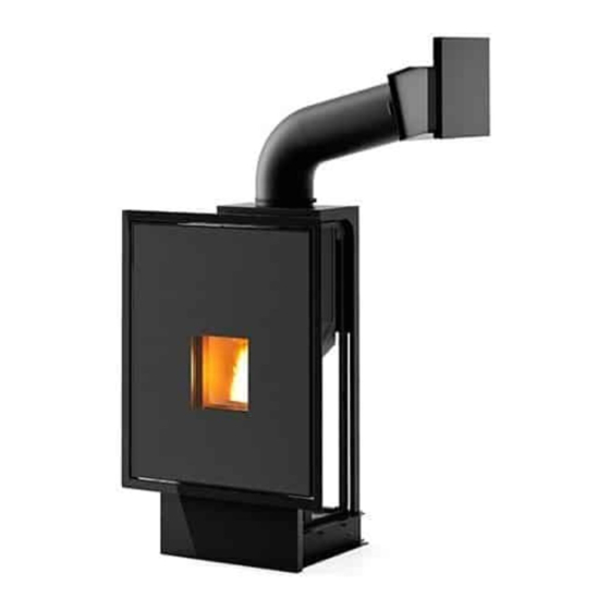
3-INSTALLAZIONE E MONTAGGIO 3-DRAWINGS AND TECHNICAL FEATURES DRAWINGS AND CHARACTERISTICS DIMENSIONS OF VIVO 85 PELLET HYDRO (dimensions in mm) Ø48 - A 659.5 127.5 127.5 Ø80 - U A = COMBUSTION AIR U= SMOKE OUTLET... - Page 21 3-DRAWINGS AND TECHNICAL FEATURES TECHNICAL CHARACTERISTICS VIVO 85 PELLET HYDRO Nominal output power: 22.3 kW (19178 kcal/h) Nominal power output (H 18.0 kW (15480 kcal/h) Minimum power output: 4.4 kW (3784 kcal/h) Minimum power output (H 3.0 kW (2580 kcal/h) Efficiency at Max 92.5% Efficiency at Min...
-
Page 22: 4-Installation And Assembly
4-INSTALLATION AND ASSEMBLY PREPARATION AND UNPACKING The product is supplied in two packages. The pallet with the Vivo 85 Hydro product, with a box on top, with pipe, loading hatch and ventilation grille. PRODUCT PACKAGING Open the packing, remove the product from the pallet and place it in the selected position, ensuring it complies with the specifications. - Page 23 4-INSTALLATION AND ASSEMBLY POSITIONING Before placing the product, assess optimal positioning condition. INSTALLATION PREMISE Evaluate the following elements: The product’s support plane must have the following features: • withstand the weight of the product and any accessories • perfectly level After ascertaining the required conditions for correct installation, proceed with assembling the product: •...
- Page 24 PELLET LOADING CHUTE ASSEMBLY Another choice to be made before placing the product is to define the side where to install the chute for loading the fuel. Vivo 85 Hydro pellet is delivered with two clamps, the connection pipe and the chute with hatch.
- Page 25 The bottom part of cladding “F” must not be built at the time of installation. The product remains flush with the built wall, and the bottom front part (with the hole on the wall) of Vivo 85 Hydro must be painted with indoor paint used for the wall finish.
- Page 26 4-INSTALLATION AND ASSEMBLY HOLE FOR PELLET LOADING HATCH ASSEMBLY The product can be installed on a masonry base, built at the time of installation, or a support (optional) can be purchased, to raise the product to a suitable height. The measurements, recommended by us, range from 50 to 60 cm under the surface that product sits on. When drilling the hole for loading hatch assembly, there are compulsory measurements provided by the length of the loading pipe, that need to be observed.
- Page 27 4-INSTALLATION AND ASSEMBLY HATCH ASSEMBLY After performing wiring, before permanently fastening the hatch to the hood, carry out an operation test. If the test has been successful fasten the hatch to the hood with four screws, using the four holes on the hatch frame marked with letter (B).
- Page 28 4-INSTALLATION AND ASSEMBLY VENTILATION GRILLES It is obligatory to install the supplied ventilation grilles or grilles that assure the same features and the same air passage section. The company is not liable for any damage to the structure or to the electric components caused by failure to comply with this warning.
- Page 29 4-INSTALLATION AND ASSEMBLY OPENING/CLOSING THE DOOR CAUTION! The door must be closed properly for the stove to work correctly. Use suitable protective clothing (for example gloves) to open the door of the stove. The aesthetic door is fitted with a pressure closure and therefore does not feature any handles or handgrips. It will hook on or unhook from the closure device on the side of the door by simple pressure.
- Page 30 4-INSTALLATION AND ASSEMBLY PULLING THE PRODUCT OUT PARTIALLY • Open the aesthetic door (Fig.A) • remove the two screws “k” (Fig.B) • pull the product out (Fig.C). Once the screws are removed, simply pull slightly towards you to extract the movable part like a standard drawer.
- Page 31 4-INSTALLATION AND ASSEMBLY PULLING THE PRODUCT OUT COMPLETELY To pull the product out completely, you need to remember to empty out the system and disconnect the pipes from the product. When the product is partially pulled out, proceed as follows: •...
-
Page 32: 5-Precautions Before Start-Up
5-PRECAUTIONS BEFORE START-UP BEFORE START-UP GENERAL PRECAUTIONS Remove any objects that may burn from the firebox and glass (instructions manual, various adhesive labels or any polystyrene). Check that the brazier is positioned correctly and rests properly on the base. The first start-up may not be successful as the feed screw is empty and does not always manage to load the required amount of pellets in time to light the flame. - Page 33 5-PRECAUTIONS BEFORE START-UP DO NOT EXPECT HEATING EFFICIENCY IMMEDIATELY!!! THE PRODUCT NEEDS SOME RUNNING-IN TIME. It is extremely important to make sure the product does not reach high temperatures straight away, but to increase the temperature gradually using low power at first. This will prevent damage to the welds and the steel structure.
- Page 34 5-PRECAUTIONS BEFORE START-UP LOADING THE PELLETS The fuel is loaded through the side or front hatch to be mounted onto the cladding, which allows access to the fuel loading chute. The loading procedure is facilitated if performed in a number of steps as described below: •...
- Page 35 5-PRECAUTIONS BEFORE START-UP SAFETY WHAT TO DO IF SMOKE LEAKS INTO THE ROOM OR IN CASE OF EXPLOSION DAMAGING THE DEVICE: SWITCH IT OFF, VENTILATE THE ROOM AND IMMEDIATELY CONTACT THE INSTALLER/TECHNICIAN IN CHARGE OF ASSISTANCE. User Training In ALL cases, the technician in charge of installation and first-start-up MUST carry out a thorough handover of the appliance to the homeowner / end user.
-
Page 36: 6-Hydraulic Connection
6-HYDRAULIC CONNECTION HYDRAULIC CONNECTION IMPORTANT! The connection of the stove to the plumbing system must be carried out ONLY by authorised personnel who are capable of carrying out installation properly in compliance with current standards in the country of installation. The company will not be held responsible for damage to people or property in the event of failed operation if the aforementioned warning is not observed. - Page 37 6-HYDRAULIC CONNECTION CONNECTING THE SYSTEM Make the connections to the corresponding fittings shown in the diagram above. Make sure the pipes are not placed under tension or undersized. If installing the product involves another pre-existing system complete with heating equipment (gas boiler, methane boiler, fuel oil boiler, etc...), it is strongly recommended that you contact a qualified operator who subsequently will be responsible for the compliance of the system with the applicable laws in force.
- Page 38 6-HYDRAULIC CONNECTION CLEANING THE SYSTEM It is mandatory for the connections to be easy to disconnect by way of unions with rotating connections. Always install cut-off shutters in the system leading to the product so as to disconnect it from the hydraulic system should it be necessary to move or relocate it, to perform routine and/or special maintenance.
- Page 39 6-HYDRAULIC CONNECTION WATER CHARACTERISTICS The characteristics of the water used to fill the system are very important to prevent the build-up of mineral salts and the formation of incrustations along the pipes, in the boiler and in the heat exchangers. Therefore, please GET YOUR PLUMBER’S ADVICE CONCERNING: •...
- Page 40 6-HYDRAULIC CONNECTION INSTALLATION DIAGRAM FOR HEATING SYSTEM WITHOUT DOMESTIC HOT WATER KIT This diagram is provided by way of example and, accordingly, is not a project drawing.
- Page 41 6-HYDRAULIC CONNECTION HEATING INSTALLATION DIAGRAM IN COMBINATION WITH A STORAGE CYLINDER This diagram is provided by way of example and, accordingly, is not a project drawing Technical Dept. - All rights reserved - Reproduction is prohibited...
- Page 42 6-HYDRAULIC CONNECTION INSTALLATION DIAGRAM IN COMBINATION WITH A STORAGE TANK This diagram is provided by way of example and, accordingly, is not a project drawing.
- Page 43 6-HYDRAULIC CONNECTION SETTINGS TO BE CARRIED OUT BEFORE THE INITIAL START-UP ON/OFF When the power supply cable is connected to the bottom of the product, place the switch, which is on the pellet loading hatch, in position (I). The luminous switch button will light up. The product stays off and an initial screen page appears on the panel with the word OFF.
- Page 44 6-HYDRAULIC CONNECTION CONTROL PANEL LOGIC Some useful information is provided below to understand the navigation logic and use of the control panel: • The brightness of the control panel switches off after approximately 30 seconds if the keyboard is not used. To turn the back-lighting on again, simply press any button on the panel.
- Page 45 6-HYDRAULIC CONNECTION SETTING CURRENT TIME AND DAY Press the relative MENU key and SET will appear. Enter SET and the programme will appear to change: hour - minutes - day of week - day of month - month - year For example, if you need to change the time, when ORA (HOUR) appears on the screen, press SET, and the hour will start flashing in the middle of the screen.
- Page 46 6-HYDRAULIC CONNECTION LANGUAGE SETTINGS Press the MENU key then scroll with the keys on the bottom right or left, until IMPOSTAZIONI (SETTINGS) appears, press SET and LINGUA (LANGUAGE), will appear, press SET again and set the required language. By standard, the days of the week are identified by acronyms based on the language selected on the panel. In English, for example: Monday Thursday Sunday...
- Page 47 6-HYDRAULIC CONNECTION RECIPE SELECTION PROCEDURE On the control panel menu, the word “Ricetta (Recipe)” will appear under the settings menu. This function is designed to increase or decrease hopper pellet loading, and is represented as follows: • To increase it: +1 +2 +3 equal to 10-20-30% more than the standard factory setting recipe. •...
- Page 48 6-HYDRAULIC CONNECTION COMPULSORY CONNECTION FOR EXTERNAL ROOM THERMOSTAT (3) OR STORAGE TANK It is necessary to connect the stove to external thermostat “3” or a storage tank; it is also possible to set up a connection with home automation control unit “4”. If you wish to connect the modem, you must do so with terminal “2”. For the connection it is necessary to connect the cables to the product board in the positions identified below.
- Page 49 6-HYDRAULIC CONNECTION AUTOMATIC MODE WITH AUTO-ECO This mode changes product operation to automatic: when the user-set temperature is reached, the product switches to power 1 for a brief amount of time and then, if the temperature stays stable and higher than the set value, it switches off. The appliance only automatically switches back on when the room/water request more heat (not before the required product cooling period).
- Page 50 6-HYDRAULIC CONNECTION SLEEP FUNCTION This function is only visible when the product is on, and it has the purpose of making programmed power-off selection quicker, without having to programme the CRONO (CHRONO) built into the product. A simple explain of the SLEEP function, is that it makes it possible to switch the product off starting from a minimum of + 10 minutes from the current time and a maximum of 23.50 hours.
- Page 51 6-HYDRAULIC CONNECTION CRONO (CHRONO) This operating mode makes it possible to programme switching the product on and off automatically. Stoves normally have their CRONO (CHRONO) mode deactivated. The fundamental settings of the CRONO (CHRONO) mode are: • Power on/off time selection •...
- Page 52 6-HYDRAULIC CONNECTION SETTING A CUSTOMISED PROGRAMME There are 62 selectable daily programmes and it is possible to choose a different programme for every day of the week. To activate this option proceed as described above to set a weekly programme, except, instead of selecting one of the programmes contained in the weekly programmes table (between P01 and P10) select the UTENTE (USER) programme.
- Page 53 6-HYDRAULIC CONNECTION PRE-SET WEEKLY AND DAILY PROGRAMMES WEEKLY PROGRAMMES The weekly programmes set by the manufacturer and saved in the product control panel have been developed to satisfy the most part of the users who are either out of the house during work hours (labourers, shop owners, office workers, shift workers, etc..) or people who spend most of the day at home (home-makers, elderly, etc..).
- Page 54 6-HYDRAULIC CONNECTION DAILY PROGRAMMES Daily Time table programmes...
- Page 55 6-HYDRAULIC CONNECTION Daily Time table programmes Technical Dept. - All rights reserved - Reproduction is prohibited...
- Page 56 6-HYDRAULIC CONNECTION PRACTICAL EXAMPLE OF DAILY PROGRAMMING SETTING A DAILY PROGRAMME Let’s take, for example, a user without set daily hours (self-employed, etc..), yet who knows that he/she will be in the house on the following days at the following times: MONDAY at home until 10:00 and after 17:00 TUESDAY...
-
Page 57: 8-Safety Devices And Alarms
8-SAFETY DEVICES AND ALARMS SAFETY DEVICES The product is supplied with the following safety devices: SMOKE TEMPERATURE PROBE It detects the temperature of the smoke, thereby enabling start-up or stopping the product when the temperature drops below the preset value. PELLET HOPPER TEMPERATURE PROBE If the temperature exceeds the preset safety value, it immediately stops product operation, which must cool down before the probe is restored and the product restarted. - Page 58 8-SAFETY DEVICES AND ALARMS ALARM ALERTS If an operating anomaly occurs, the product enters the shutdown phase due to an alarm and informs the user regarding the type of fault by means of a 3 digit code that remains displayed on the emergency panel. The alarm is indicated permanently by the relative 3 digit code, by a flashing red LED that lights up on the emergency panel and an intermittent sound signal for the first 10 minutes of the alarm.
- Page 59 8-SAFETY DEVICES AND ALARMS The smoke probe is faulty and does not detect Contact an authorised service centre to have the the exhaust smoke temperature properly. component replaced. The ignition plug is faulty. Contact an authorised service centre to have the component replaced.
- Page 60 8-SAFETY DEVICES AND ALARMS BLOCKED PRODUCT The following may cause the product to be mechanically blocked: • structure overheating (“A03”). • smoke overheating (“A04”). • During product operation, uncontrolled air has entered the combustion chamber or there is an obstruction in the flue (“A05”). •...
-
Page 61: 9-Recommendations For Safe Use
9-RECOMMENDATIONS FOR SAFE USE ONLY CORRECT INSTALLATION AND APPROPRIATE MAINTENANCE AND CLEANING OF THE APPLIANCE CAN GUARANTEE CORRECT OPERATION AND SAFE USE OF THE PRODUCT We would like to inform you that we are aware of cases of malfunctioning of domestic pellet-fuelled heating products, mainly due to incorrect installation and inappropriate maintenance. -
Page 62: 10-Cleaning And Maintenance
10-CLEANING AND MAINTENANCE EXAMPLE OF A CLEAN BRAZIER EXAMPLE OF A DIRTY BRAZIER Only by properly servicing and cleaning the product is it possible to ensure its safety and correct operation. ATTENTION! All the cleaning operations of all parts must be performed with the product completely cold and the plug disconnected. - Page 63 10-CLEANING AND MAINTENANCE Ash pan cleaning Remove and empty ash pan “D”. Wipe away any residual ash before reinserting the pan. Your experience and the quality of the pellets will determine the ash pan cleaning frequency. However, it is recommended not to exceed 2 or 3 days. CLEANING THE GLASS It is recommended to clean the ceramic glass with a dry brush, or if it is very dirty, spray a little specific detergent and clean with a cloth.
- Page 64 10-CLEANING AND MAINTENANCE CLEANING THE LOWER COMPARTMENT Open aesthetic door “A”, open firebox door “B” and begin cleaning. Clean around the brazier “C”. Remove the pan “D” and the brazier “C”. Loosen the screws and remove the fumes plug “E” and using the nozzle of a vacuum cleaner, remove any ash and soot that may have built up in the lower exchanger indicated by the arrow.
- Page 65 10-CLEANING AND MAINTENANCE PERIODIC CLEANING PERFORMED BY A QUALIFIED TECHNICIAN CLEANING THE SMOKE DUCT AND FITTING To clean and maintain the smoke fan (1) you need to pull the product out of its housing. The fan is located in the middle, under the firebox. Clearly, the smoke evacuation fan must be removed to perform these maintenance operations.
- Page 66 10-CLEANING AND MAINTENANCE REPLACING THE OVERPRESSURE DISCHARGE FOR THE COMBUSTION CHAMBER Overpressure rubber bushing “G” of the combustion chamber (fig. A) may get worn and/or damaged, it is therefore necessary to replace it once a year to ensure correct system operation. To replace it, follow the instructions below •...
- Page 67 10-CLEANING AND MAINTENANCE END-OF-SEASON SHUTDOWN At the end of each season, before switching the product off, it is recommended to remove all the pellets from the hopper with a vacuum cleaner with a long pipe. When not in use, the product must be disconnected from the mains power supply. CHECKING THE INTERNAL COMPONENTS ATTENTION! The internal electromechanical components must only be checked by qualified personnel whose technical expertise...
-
Page 68: 11-Faults/Causes/Solutions
11-FAULTS/CAUSES/SOLUTIONS ATTENTION! All repairs must only be carried out by a specialised technician, with the product switched off and the plug disconnected. If the product is NOT used as described in this manual, the manufacturer declines all liability for any damage caused to persons and property. - Page 69 11-FAULTS/CAUSES/SOLUTIONS ANOMALY POSSIBLE CAUSES SOLUTIONS The product works for a few minutes Start-up phase is not completed. Repeat start-up. and then switches off. Temporary power cut. Wait for the automatic restart. Clogged smoke duct. Clean the smoke duct. Faulty or malfunctioning temperature Check and replace the probes.
- Page 70 11-FAULTS/CAUSES/SOLUTIONS ANOMALY POSSIBLE CAUSES SOLUTIONS The product always runs at maximum The room thermostat is in the maximum Reset the temperature of the thermostat. power when in automatic mode. position. Malfunctioning temperature probe. Check the probe and replace it if necessary. Faulty or malfunctioning control panel.
- Page 71 Check and clean the boiler. Low product power. Check that the product is properly sized for the requirements of the system. Poor pellet quality. Use MCZ pellets. Condensation in boiler. Incorrect temperature setting. Set the product at a higher temperature. Insufficient fuel consumption.
-
Page 72: 12-Wiring Diagrams
12-WIRING DIAGRAMS 10 9 MOTHERBOARD WIRING KEY CONTROL PANEL 11. TANK TEMPERATURE OVERLOAD CUT-OUT FLOW SWITCH (if there is one) 12. ROOM FAN (if there is one) WATER TEMPERATURE PROBE 13. 3-WAY DIVERTER VALVE (if there is one) SMOKE TEMPERATURE PROBE 14. - Page 76 MCZ GROUP S.p.A. Via La Croce n°8 33074 Vigonovo di Fontanafredda (PN) – ITALY Telephone: +39 0434/599599 r.a. Fax: +39 0434/599598 Internet: www.mcz.it e-mail: mcz@mcz.it 8901507500 REV. 0 21/09/2015...
Need help?
Do you have a question about the Vivo 85 Hydro and is the answer not in the manual?
Questions and answers