
Subscribe to Our Youtube Channel
Related Manuals for GEA Trailer Super Pump for 20-Foot Above Ground Tank


Summary of Contents for GEA Trailer Super Pump for 20-Foot Above Ground Tank
- Page 1 db^ c~êã qÉÅÜåçäçÖáÉë Trailer Super Pump for 20-Foot Above Ground Tank PTO pumps Instruction Manual / Installation Instructions / Parts List 2010-9015-011 08-2009 db^ c~êã qÉÅÜåçäçÖáÉë J qÜÉ êáÖÜí ÅÜçáÅÉK...
-
Page 2: Table Of Contents
Preface ............... . Information on the instructions . - Page 3 Safety instructions for operation ..............Workplaces for operating personnel .
-
Page 4: Preface
Preface Information on the instructions These instructions are supplied with the product. It is designed modular and is only in relation to the mentioned product. For details of the components which are relevant to the product, please refer to the appropriate manuals. This applies especially for safety information! They should be kept close at hand and remain with the equipment even if the equipment is sold. -
Page 5: Manufacturer's Address
Manufacturer’s address GEA Houle Inc. 4591 boul. St-Joseph Drummondville, Qc, J2A 0C6 (Canada) +1 819 477 - 7444 +1 819 477 - 5565 geahoule@geagroup.com www.gea-farmtechnologies.com Customer service If necessary, please contact your nearest authorized technical dealer. 2010-9015-011 08-2009... -
Page 6: Guidelines, Laws, Standards
Guidelines, Laws, Standards The content and instructions of the following guidelines and regulations have been observed in the design and construction of this machine: RL 98/37 EC Machinery Directive RL 93/68 EC CE Marking EN 12100-1 Machine safety, basic terms, general design guidelines. -
Page 7: Manufacturer's Declaration
Drummondville, Qc, J2A 0C6 (Canada) Product category: PTO pumps Name / Model: Trailer Super Pump for 20-Foot Above Ground Tank The named product is in conformity with the requirements of the following European directives: Machinery Directive 98/37/EC amended, CE Marking 93/68/EEC amended. -
Page 8: Warranty And Exclusions
The buyer does not modify or try to repair the equipment or parts of the equipment without authorization; The liability of the company GEA Houle Inc. and its dealers, in pursuance of this warranty, consists only in repairing or replacing the defective parts. GEA Houle Inc. -
Page 9: Safety
Safety Owner’s obligation of care The product has been designed and constructed while taking account of a potential risk analysis and after careful selection of the harmonized standards and other technical specifications to be complied with. It therefore guarantees a maximum level of safety. This safety can only be achieved in practice on the farm however when all of the necessary measures have been taken. -
Page 10: Explanation Of The Safety Symbols Used
Escape routes are marked by means of signs in accordance with national regulations! The personal protective equipment required for personnel carrying out operation, maintenance and repairs is made available and used. No one must enter into a manure pit at any time. The “Safety Procedures for Confined Spaces”... -
Page 11: Basic Safety Instructions
Basic safety instructions Danger! There are warnings about specific residual dangers in the corresponding chapters. Attention! If the work requires special qualifications, these are described in the corresponding chapters! There are risks involved in the operation and maintenance of equipment for dairy farms. -
Page 12: Protective Devices
Protective devices Protective devices Protective guard for power take off driveline (part no.) European Safety cap (part no. 2010-7704-670) Safety symbols, warnings, warning signs and labels Danger! - Toxic gases (American model) Manure produces toxic gases that can cause loss of consciousness, asphyxia or death in few seconds. - Page 13 Maximum 540 RPM (part no. 2010-4703-430) Maximum 1000 RPM (part no. 2010-4703-440) 2010-9015-011 08-2009...
-
Page 14: Description
For safety reasons, do not carry out any unauthorized changes! Any planned changes must be approved by the manufacturer in writing. Parts and special equipment which have been obtained elsewhere must be expressly authorized by GEA Houle, in writing, for use in GEA Houle components and installations. 2010-9015-011... -
Page 15: Design Of The Equipment
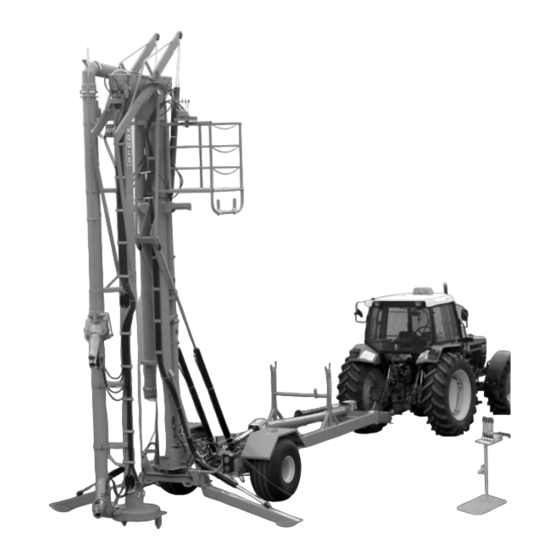
Design of the equipment Design The Trailer Super Pump for 20 -Feet Above Ground Tank consists of: a vertical pump mounted on a trailer with an articulating joint to allow the pump to be raised up and over the side of an above ground manure tank. two adjustable nozzles to homogenize manure. -
Page 16: Technical Data
Technical Data Performance data 8” Super pump with impeller 21” x 4 blades and 14” intake. Nozzle Nozzle Shut-off Maximum RPM/ ratio diameter pressure pressure head * 1000/ -26% 3¼” [83 mm] 35 psi [2.4 bar] 40 psi [2.8 bar] 65 ft [19.8 m] 1000/ -26% 4”... - Page 17 Hydraulic hoses I.D. ¼” ½” ¾” O.D. 0.58” 0.86” 1.10” Quantity of braids 400 bar 276 bar 105 bar Service pressure (5,800 psi) (4,000 psi) (1,525 psi) -40ºC to 100ºC Service temperature (-40ºF to 212ºF) Tire Tire brand Tire model Pressure Tire dimensions Weight...
-
Page 18: Main View
Main view Agitation / loading indicator rod Gearbox Up = loading Directional valve Down = agitation Hydraulic controls for agitation nozzles Pump for cooling system Agitation nozzle Balcony Internal member Directional valve cylinder Agitation nozzle with hydraulic cap External member Access to the driveline joint Impeller housing... -
Page 19: Transport
Transport Special personnel qualification required for transport Transport may only be performed by specially qualified personnel in accordance with the safety instructions. National driver’s licence for drive-on machines, stackers and other trucks. Also see the section on ”Personnel qualification”. Safety instructions for transport To prevent damage to property and/or life-threatening injury to personnel always observe the following: Only the load suspension and support equipment indicated here should be... - Page 20 Danger! Do not stand underneath suspended loads. Suspended loads may fall, so there is a danger of death! Travel (short distances) The pump must be moved with a farm tractor. Minimum towing capacity of; 9,250 lb [4195 kg] Maximum speed; 25 mph [40 km/h] Travel (long distances) For long distance transportation, use a...
-
Page 21: Transport
Transport Attention! Moving the pump Lower the main frame completely and set the outside member on the supports for traveling. Internal member resting on the external member External member resting in the transportation supports Attention! Moving the pump The pump must be moved on a farm tractor with a minimum towing capacity of 9,250 lb [4195 kg]. -
Page 22: Installation
Installation If necessary, please contact your nearest authorized technical dealer. Special personnel qualification required for installation Installation may only be carried out by specially qualified personnel in accordance with the safety instructions. Also see the section on ”Personnel qualification”. Safety instructions for installation Danger! Read Instructions First! To prevent serious injury or death, do not operate or service this machine without first reading and... -
Page 23: Assembly Preparations
Assembly preparations Special tools Attention! To lift the pump and steady in place when assembling, use a lifting device with a minimum capacity of; 9,250 lb [4195 kg]. Fork lift truck Safety Chain Crane Front end loader Locally purchased items A ladder must be provided to access the operator balcony when the pump is in position over the tank wall. -
Page 24: Environmental Prerequisites For Setting Up
Environmental prerequisites for setting up Danger! Unexpected movement! Before assembling the pump, make sure the trailer is on a flat and firm surface and that the rear wheels are blocked. Chock the wheels to prevent the trailer from rolling ahead or back. Use the hand jack or a suitable lifting device to raise the front of the trailer. -
Page 25: Pump Assembly
Pump assembly Tow bar assembly Raise the trailer frame using the proper lifting device. Frame Position the blocks underneath the frame and rest the frame on the blocks. Hold up and position the tow bar using the proper lifting device. Blocks Tow bar Bolt the tow bar. -
Page 26: Information On Disposing Of Installation Material After Installation Is Finished
Note! On certain pump models, the reducer is used to increase the pressure of the nozzle to reach farther, cut through thick floating crust material more effectively and/or to decrease tractor horsepower required. 2nd agitation nozzle Install the 2nd agitation nozzle using the Hydraulic cap circle lock;... -
Page 27: Initial Commissioning
Initial Commissioning Special personnel qualification required for initial commissioning Initial commissioning may only be performed by specially qualified personnel in accordance with the safety instructions. Also see the section on ”Personnel qualification”. Safety instructions for initial commissioning Danger! Read Instructions First! To prevent serious injury or death, do not operate or service this machine without first reading and understanding the operator’s manuals for all of the equipment. -
Page 28: First Start
PTO driveline - Make sure the driveline guards turn freely; - Secure both ends of the driveline; - Keep all guards in place. First start Danger! Manure produces toxic gases that can cause a loss of conciousness, asphyxia or death in a few seconds. Manure agitation can produce toxic gases in buildings built above the pit. -
Page 29: Handing Over To The Owner
Handing over to the owner Declaration of conformity and CE mark (only necessary for European Union member states) A declaration of conformity must be produced and a CE mark applied if a total operational installation is assembled from individual components. If several directives apply to the total installation, the CE mark means that the requirements of all relevant directives have been met. -
Page 30: Operation
Operation Special personnel qualification required for operation Operation may only be performed by specially qualified personnel in accordance with the safety instructions. Also see the section on ”Personnel qualification”. Safety instructions for operation Danger! Read Instructions First! To prevent serious injury or death, do not operate or service this machine without first reading and understanding the operator’s manuals for all of the equipment. - Page 31 Danger! Rotating driveline keep away! Danger! Hydraulic line under pressure Escaping fluid can penetrate skin causing serious injury or death. Never use your hand to feel for leaks. Hold a scrap of cardboard to feel around for leaks. Relieve pressure prior to servicing.
- Page 32 During operation, it is strictly forbidden to remain within the hazard area! The following checks should be performed at least once a day: - Visual checks for any damage that can be seen on the outside. - check that all safety devices are working - check that all pneumatic and hydraulic hoses are leaktight and connected correctly - Never use the pump if parts of the equipment appear damaged or...
-
Page 33: Workplaces For Operating Personnel
Workplaces for operating personnel Danger! Manure produces toxic gases that can cause a loss of conciousness, asphyxia or death in a few seconds. Manure agitation can produce toxic gases in buildings built above the pit. Toxic gases can also emanate in buildings situated by the pit and / or connected to the pit by an evacuation line. -
Page 34: Description Of The Operating Elements
Description of the operating elements 7.4.1 Hydraulic controls on the balcony Hydraulic cap on agitation nozzle open/ close Agitation nozzle rotation Agitation nozzle up and down Hydraulic control valves Agitation nozzle up / down Agitation nozzle rotation Hydraulic cap on agitation nozzle 2010-9015-011 08-2009... -
Page 35: Trailer Hydraulic Controls
7.4.2 Trailer hydraulic controls Hydraulic controls Left stabilizing leg Up/Down Right stabilizing leg Up/Down External member Up/Down (Trailer cylinders) Internal member Up/Down (Articulating cylinders) 2010-9015-011 08-2009... -
Page 36: Trailer To Tractor Connections
7.4.3 Trailer to tractor connections ¼” NPT hose (directional valve system) ½” NPT hose (hydraulic controls) Trailer lights 7.4.4 Ball valves on the stabilizing legs, articulating and trailer hydralic cylinders Closed Open Trailer cylinders Articulating Stabilizing leg cylinders cylinders 2010-9015-011 08-2009... -
Page 37: Jack Stand
7.4.5 Jack stand Down Storage Transport position position 2010-9015-011 08-2009... -
Page 38: Circle Lock Cap On Discharge Pipe
7.4.6 Circle lock cap on discharge pipe If the transfer hose is not connected, install the circle lock on discharge pipe. Danger! Never unlock a circle lock cap under pressure! Unlocking a circle lock cap under pressure could cause serious injuries to anyone standing near the cap. -
Page 39: Operating
Operating Danger! Manure produces toxic gases that can cause a loss of conciousness, asphyxia or death in a few seconds. Manure agitation can produce toxic gases in buildings built above the pit. Toxic gases can also emanate in buildings situated by the pit and / or connected to the pit by an evacuation line. -
Page 40: Moving The Pump
7.5.1 Moving the pump Lower the main frame completely and set the outside member on the supports for traveling. Attention! Moving the pump The pump must be moved on a farm tractor with a minimum towing capacity of; 9250 lb [4195 kg]. The hitch, tires, wheels, hubs and axles of the pump are designed for agricultural use only. - Page 41 Make sure the stabilizing legs are locked in a raised position; The ball valves must be closed to lock Closed the legs. Attention! The ball valves must be closed to lock the legs. 2010-9015-011 08-2009...
- Page 42 Rest the PTO drivelines onto their respective transportation supports; Lock the pump using the chain or cable Chain tensioner; tensioner Secure the hydraulic system controls on the pump using the T-shape locking handle. Hydraulic controls T-shaped locking handle 2010-9015-011 08-2009...
-
Page 43: Positioning The Pump
7.5.2 Positioning the pump Danger! Make sure the trailer wheels are on a flat and firm surface before operating the articulation and lifting cylinders. Attention! Make sure the hydraulic circuit of the tractor contains sufficient hydraulic oil to safely articulate the pump up and down. Attention! Always check the oil level before operating. - Page 44 Position the controls near the pump. Hydraulic controls Open the ball valves on the stabilizing Open legs. Activate the cylinders of the stabilizing legs so that the pump is leaning firmly in a horizontal position. Close the ball valves of the stabilizing legs to secure the pump.
-
Page 45: Raising The Pump
7.5.3 Raising the pump Danger! Keep all articulated components away from electric power lines. Operate the articulation cylinder to lift the main frame to the maximum; Tank wall Main frame Articulation cylinders 2010-9015-011 08-2009... -
Page 46: Lowering The Pump
7.5.4 Lowering the pump Danger! Keep all articulated components away from electric power lines Operate the lifting cylinders to lift the outside member. Tank wall Lifting cylinders External member Operate the articulation and lifting cylinders to lower the pump inside the tank. Set the main frame parallel to the wall of the tank Articulation Tank wall... -
Page 47: Agitation Mode
7.5.5 Agitation mode Danger! Rotating driveline keep away! Turn off the tractor before installing or removing the PTO driveline. Note! The hydraulic cap on the bottom nozzle may be used to shut off flow to bottom nozzle and therefore increase pressure and flow to the top nozzle. - Page 48 Hydraulic controls Resting pipes Balcony Ladder Using the nozzle controls (rotation, up/down), agitate the content of the pit. Operate the agitation nozzle to break chunks and direct them towards the pump intake. A boltable tip may be installed on the nozzle to improve thick crust cutting.
-
Page 49: Manure Transfer Mode
7.5.6 Manure transfer mode Note! Thoroughly agitate the content of the reservoir before transferring the manure. Note! The hydraulic cap on the bottom nozzle must be closed when transfering manure to other storage or spreader. Danger! Never unlock a circle lock cap under pressure! Unlocking a circle lock cap under pressure could cause serious injuries to anyone standing near the cap. - Page 50 Remove the cap of the discharge pipe; Install the loading pipe using the circle lock. Stabilize the loading pipe according to the instructions supplied with the loading pipe. Using the lever inside the cabin of Indicator rod at the tractor, set the directional valve its highest to the transfer mode at its highest position...
- Page 51 Position back the circle lock cap on the auxiliary pipe using the circle lock. Note When the PTO RPM is at minimum, the directional valve can be switched from the loading mode to the agitation mode between two spreader loads. 2010-9015-011 08-2009...
- Page 52 Repositioning for transportation Danger! Rotating driveline keep away! Turn off the tractor before installing or removing the PTO driveline. Remove the PTO drivelines from the pump and install them on their supports. Lower the jack shaft guard by removing the lock pin. Lock pin Disconnect the loading pipe and...
- Page 53 Operate the articulation cylinders to raise the pump over the wall of the tank; Operate the lifting cylinders to lower the outside member until it reaches the support; Operate the articulation cylinders to lower the main frame. The main frame must lean on the outside member.
- Page 54 Lock the pump using the chain or cable Chain tensioner; tensioner Open the stabilizing legs cylinder ball Open valves. Activate the stabilizing legs cylinders to lift them up. Close Once accomplished, close the ball valves. Secure the hydraulic system controls on Hydraulic Fastening for the pump using the T-shape locking...
-
Page 55: Operating Faults
Operating faults If necessary, please contact your nearest authorized technical dealer. Special personnel qualification required for troubleshooting Troubleshooting may only be performed by specially qualified personnel in accordance with the safety instructions. Also see the section on ”Personnel qualification”. Safety instructions for troubleshooting Danger! Read Instructions First! To prevent serious injury or death, do not operate or service this machine without first reading and... -
Page 56: Troubleshooting Possible Faults
Danger! Hydraulic line under pressure Escaping fluid can penetrate skin causing serious injury or death. Never use your hand to feel for leaks. Hold a scrap of cardboard to feel around for leaks. Relieve pressure prior to servicing. Troubleshooting possible faults Symptom Possible cause Remedy... -
Page 57: Maintenance
Maintenance If necessary, please contact your nearest authorized technical dealer. Special personnel qualification required for maintenance work Maintenance work may only be performed by specially qualified personnel in accordance with the safety instructions. Also see the section on ”Personnel qualification”. Safety instructions for maintenance Danger! Read Instructions First! To prevent serious injury or death, do not... - Page 58 Before carrying out any maintenance work, make sure of the following: The area for the maintenance work and access to the working area should be secured over a wide area and there should not be any unauthorized people in the working area. Disconnect all pressure units from the pressure source and make sure they cannot be switched back on again unintentionally.
- Page 59 Operation has been checked after maintenance work has been completed or parts replaced. Produce a full test report if necessary. Follow the maintenance and safety instructions on the labels affixed to the pump. Refer to section 2.5 Protective devices Maintenance and Safety Labels Do not remove the labels at any time.
-
Page 60: Inspections And Preventive Maintenance
Inspections and preventive maintenance Lubrication Danger! Manure produces toxic gases that can cause a loss of conciousness, asphyxia or death in a few seconds. Manure agitation can produce toxic gases in buildings built above the pit. Toxic gases can also emanate in buildings situated by the pit and / or connected to the pit by an evacuation line. -
Page 61: After Emptying Each Pit
9.3.1 After emptying each pit Grease joints of the driveline; Access to the driveline joints Grease all parts labeled with. 2010-9015-011 08-2009... - Page 62 Grease points 2010-9015-011 08-2009...
-
Page 63: Every 5 Hours
9.3.2 Every 5 hours Note! Use specified grease or equivalent: Red Texas 880 crown and chassis® grade 0 (2010-4300-790) 5 grease points on each joint Grease joints and sliding section of PTO driveline. On universal joints, use a high quality grease formulated specifically for intensive use. - Page 64 Remove the magnetic plug located Filling at the bottom of the oil cooler pipes. plug Collect the used oil in an appropriate container with a minimum capacity of 8 gal. [30 liters] Unscrew the access cap to the bearing housing located underneath the pump.
- Page 65 Clean and reinstall the magnetic Filling plug and the bearing housing plug access plug. Through the plug hole, pour the oil in the bearing housing and fill. Replace the filling plug. Magnetic plug of the oil cooler circuit Access to the magnetic plug of the bearing housing Reinstall the hose plug of the Gearbox...
- Page 66 Attention! After an oil change, articulate the pump in the agitation/transfer position to install the PTO drivelines. Run the pump for 1 minute only, then turn off the pump. Remove the PTO drivelines and articulate the pump in the transportation position. Agitation/transfer position Transportation...
- Page 67 To change the oil of the external member: Remove the drain plug located at the Oil level hose 90º base of the external member. elbow Collect the used oil in an appropriate container with a minimum capacity of 8 gal. [30 liters] Remove the access cover to the rear of the external member and clean Access...
- Page 68 Reinstall the 90° elbow on the lower gearbox and reconnect the hose; Pour gearbox oil through the hole located on the upper gearbox. Approximately; 2 gal. [8 liters] SAE 80W90 Oil plug Remove the oil plug located at the Oil plug the bottom of the external member.
-
Page 69: Repairs
Checking the oil level of the external member: Make sure transparent hose Oil level hose showing the oil level is full. Add oil if necessary (SAE 80W90 gear oil). Attention! Wipe out any oil spill. Safely dispose of used oil by following local and/or state regulations concerning the proper handling of dangerous goods. -
Page 70: Decommissioning
Decommissioning 10.1 Special personnel qualification required for decommissioning Decommissioning may only be performed by specially qualified personnel in accordance with the safety instructions. Also see the section on ”Personnel qualification”. 10.2 Safety instructions for decommissioning Danger! Read Instructions First! To prevent serious injury or death, do not operate or service this machine without first reading and understanding the operator’s manuals for all of the equipment. -
Page 71: Temporary Decommissioning
10.3 Temporary decommissioning Danger! Rotating driveline keep away! Turn off the tractor before lubricating or cleaning the pump. Storage Park the pump on a flat and firm surface. Block the wheels of the trailer; Remove the cover of the directional valve and clean the housing. Be sure to clean out any accumulation of dry manure;... -
Page 72: Final Decommissioning/Disposal
To prevent corrosion, spread a film of oil on all moving parts. 10.4 Final decommissioning/disposal After final decommissioning, handle all components properly and dispose of them in accordance with valid local regulations on waste disposal and utilization. 2010-9015-011 08-2009... -
Page 73: Appendix
Appendix 11.1 Label position C,E,G,J,K C,E,G,J,K 2010-9015-011 08-2009... - Page 74 American European 2010-4700-400 2019-4703-660 2099-4720-010 2099-4725-070 2099-4720-020 2099-4720-070 2099-4725-090 2099-4725-110 2099-4721-020 2003-4701-240 2010-9015-011 08-2009...
- Page 75 American European 2010-4701-590 2010-4703-430 2010-4703-440 2010-4703-790 2010-4703-381 2010-4703-380 2010-9015-011 08-2009...
-
Page 76: Abbreviations
11.2 Abbreviations Units ° Degrees (angles) CE/ EC European Union Centimeters Clockwise Counterclockwise Gallon Horsepower ” (in) Inch (= 25.4 mm) Incorporated Kilograms km/h Kilometers per hour Left or liters Pounds Meter Millimeters Maximum Minimum Miles per hour National coarse thread Power take-off Quebec (Canada) Right... -
Page 77: Hydraulic Diagrams
11.3 Hydraulic diagrams Hydraulic control Note! The diagram illustrates all hydraulic controls available on the pump. The dashed frame shows a component equipped with a control lever. * All components equipped with a control lever may be connected togheter using the same tractor outlet. A Directional valve cylinder B Nozzle height cylinder C Nozzle rotation motor... - Page 78 Cooling system Internal member External member (pump) Oil pump ¾” [19 mm] Cooling pipes Oil pump 3/16” [4.7 mm] Restrictor 2010-9015-011 08-2009...
-
Page 79: Consistency Test
11.4 Consistency test The following test must be performed to find the viscosity of well-agitated slurry. Set a 24” (60cm) disc over a pail. Slowly pour enough slurry to get overflow all around the disc. After 1 minute of rest, measure the thickness of slurry at the center of the disc. - Page 80 êáÖÜí ÅÜçáÅÉK db^ c~êã qÉÅÜåçäçÖáÉë GEA Houle Inc. QRVN ÄçìäK píJgçëÉéÜ, aêìããçåÇîáääÉI nÅI gO^ M`S E`~å~Ç~F qÉäK HN UNV QTT J TQQQI c~ñK HN UNV QTT J RRSR ïïïKÖÉ~JÑ~êãíÉÅÜåçäçÖáÉëKÅçã 2010-9015-011 08-2009...
Need help?
Do you have a question about the Trailer Super Pump for 20-Foot Above Ground Tank and is the answer not in the manual?
Questions and answers