
Subscribe to Our Youtube Channel
Related Manuals for GEA durietta I Bloc


Summary of Contents for GEA durietta I Bloc
- Page 1 GEA Hilge durietta I Bloc Installation and operating instructions English Translation of the original operating manual BA.017.BYY.001.01.10.GB engineering for a better world GEA Hilge...
- Page 2 Declaration of conformity Declaration of conformity as per EC Directive 2006/42/EC, Appendix II A The declaration refers to complete pump units (with and without motor). HILGE GmbH & Co. KG Hilgestraße 37-47 D-55294 Bodenheim hereby declare that the complete machine •...
-
Page 3: Table Of Contents
1. Introduction _________________________________________________ 5 1.1 Target group_________________________________________________________________5 1.2 Symbols and formatting ________________________________________________________5 1.3 References to the document ____________________________________________________5 2. Safety ______________________________________________________ 6 2.1 Instructions for the operator _____________________________________________________6 2.1.1 General information_______________________________________________________6 2.2 Safety instructions in the operating manual _________________________________________6 2.3 Identification of instructions in the operating manual __________________________________7 2.3.1 Structure of safety instructions ______________________________________________7 2.4 Qualifications and training of personnel ___________________________________________8 2.5 Hazards caused by failure to follow the safety instructions _____________________________8... - Page 4 5.1 Start-up ___________________________________________________________________ 25 5.1.1 Check application conditions ______________________________________________ 25 5.1.2 Starting up the pump ____________________________________________________ 25 5.1.3 Functional check of the mechanical seal _____________________________________ 25 5.1.4 Shut-down_____________________________________________________________ 26 5.1.4.1 Shutting down the pump _____________________________________________ 26 5.1.5 Cleaning the pump after shut-down _________________________________________ 26 6.
-
Page 5: Introduction
Introduction 1. Introduction Abstract This section describes the requirements which are important for reading and understanding this manual. You will learn the symbols and formats that make the reading easier. 1.1 Target group This operating manual is intended for: • the operators of the pump •... -
Page 6: Safety
Safety 2. Safety Abstract This section describes what you have to consider for your own safety. You will learn the structure and identifica- tion of safety instructions. Read this important section attentively! 2.1 Instructions for the operator All our pumps are professionally packed before they leave our 2.1.1 General information warehouse to avoid damage during transport. -
Page 7: Identification Of Instructions In The Operating Manual
Safety 2.3 Identification of instructions in the operating manual The safety instructions presented in this operating manual are Symbol identified as shown below. ATTENTION Fig. 1 Symbol for safety instructions A: Failure to follow these safety instructions can endanger per- sonnel. -
Page 8: Qualifications And Training Of Personnel
Safety 2.4 Qualifications and training of The employees operating, maintaining, inspecting, and in- stalling the pump must have the appropriate qualifications for personnel this work. The operator must define in detail the tasks for which the employees are responsible, the tasks of which they are in charge, and the manner in which they are supervised. -
Page 9: Unauthorized Modifications And Production Of Spare Parts
Safety W arn in g Contact with hazard substances (e. g. inhale)! Death, serious bodily injury, damage to property. Drain away leakage of hazardous pumping media in such a way that there is no danger to personnel or to the envi- ronment. -
Page 10: Transport
Safety 2.10 Transport War ni ng Falling loads! Death, serious bodily injury, damage to property. Transport work must only be performed by persons quali- fied to do so, and all safety instructions must be observed. Use suitable load carrying equipment with sufficient ca- pacity to transport the pump. -
Page 11: Repair Contract
Safety 2.12 Repair contract The duty to follow the legal regulations on work safety and the regulations on environmental protection means that all com- mercial enterprises must protect their employees, the public at large, and the environment from the harmful effects of haz- ardous materials. -
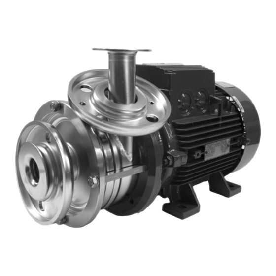
Page 12: Product Description
Product description 3. Product description Abstract This section describes the pump as well as it’s design and application. This section describes limits for applica- tion. You must know and keep these limits. 3.1 Pump overview 0107 0162 0680 0156 0107 0112 0802 0905... -
Page 13: Proper Usage
Product description 3.3 Proper usage W arn in g Improper usage! Death, serious bodily injury, damage to property. Pump only media that are specified in the order. The pump has been specially designed for that purpose. Operate the pump only in the electrical network specified in the order. -
Page 14: Pump Denomination
Product description The HILGE pump denomination is structured as shown be- 3.4.1 Pump denomination low: 32/25 durietta I pump type stages / impeller index design nominal diameter DN / DN power [kW] number of poles Tab. 1 HILGE pump denomination (example) The pump can be identified by the pump serial number. -
Page 15: Weights
Product description Design features of the described standard pumps: 3.4.5 Weights Caution: The weights can - depending on design and accessories - dif- fer from those presented. The manufacturer gives you when given the pump / order number precise information. •... -
Page 16: Maximum Operating Temperature
Product description 3.4.7 Maximum operating temperature War ni ng Exceeding the max. permitted operating temperature! Death, serious bodily injury, damage to property. Never exceed the specified operating temperatures. Design Temp. [° C] Standard design Special design Sterilization (SIP) Tab. 5 Operating temperatures 3.4.8 Maximum operating pressure War ni ng Pressure overload! -
Page 17: Mounting, Installation And Connection
Mounting, installation and connection 4. Mounting, installation and connection Abstract This chapter is intended for the maintenance and repair personnel. This section describes how to mount, adjust and install the pump.You get to know what to consider when you connect the pump to the electric mains supply and how to improve the flow in order to avoid dry running of the shaft seals. -
Page 18: Installation In The Pipeline
Mounting, installation and connection War ni ng Short circuit! Death, serious bodily injury, damage to property. In case of a vertical installation: Under no circumstances the motor should be positioned underneath the pump. If there is leakage the motor could be damaged. Align the pump in this way: 1. - Page 19 Mounting, installation and connection For example see Fig. 4. 0433.00 Fig. 4 Lubrication between slide surfaces • P - pump side • 0433.00 - mechanical seal • L - lubrication • A - atmosphere side Ca ution Dry running! Damage to property. The suction line must be absolutely leak proof and laid in such a way that no air pockets can form.
- Page 20 Mounting, installation and connection Fig. 5 Installation in the pipeline above: gravity feed mode below: suction mode P - pump M - motor BA.017.BYY.001.01.10.GB...
-
Page 21: Space Requirements
Mounting, installation and connection 4.3.1 Space requirements ATTENTION Overheating! Damage to property. Ensure sufficient ventilation. Make sure not to re absorb warm cooling air. Consider other heat sources in the area. Pay attention to motor power. Keep the minimum dis- tances. -
Page 22: Reduction Of Noise And Vibration
Mounting, installation and connection Noise and vibration are generated by the pulsating flow of the 4.3.2 Reduction of noise and vibration rotors and by the flow in pipes and fittings. The effect on the environment is subjective and depends on correct installation and the state of the remaining system. -
Page 23: Electrical Connections
Mounting, installation and connection 4.4 Electrical connections Warning Electric shock! Death, serious bodily injury. The electrical connections must be made by a qualified electrician. VDE specifications and any local regulations must be fol- lowed, especially those pertaining to safety measures. Warning Capacity overload! Death, serious bodily injury, damage to property. -
Page 24: Checking The Direction Of Rotation After Connection
Mounting, installation and connection 4.4.3 Checking the direction of rotation after connection ATTENTION Danger of dry running! Damage to property. Before checking of the direction of rotation: Fill and vent the pump. Connect the motor and briefly (for about 2 seconds) check the direction of rotation. -
Page 25: Start-Up / Shut-Down
Start-up / shut-down 5. Start-up / shut-down Abstract This section describes how to start up and shut down the pump. You get to know which inspections contribute to failure-free operation and increased life of the pump. 5.1 Start-up 5.1.1 Check application conditions Check the application conditions of the pump in this way: 1. -
Page 26: Shut-Down
Start-up / shut-down 5.1.4 Shut-down 5.1.4.1 Shutting down the pump Caution Pressure surge! Death, serious bodily injury, damage to property. Always close shut-off devices slowly! A pressure surge is an abruptly pressure increasing in the What is a pressure surge? system. -
Page 27: Maintenance / Servicing
Maintenance / servicing 6. Maintenance / servicing Abstract This chapter is intended for the maintenance and repair personnel. This section gives important information concerning maintenance and servicing of the pump. Read this section before you carry out maintenance work or troubleshooting measures! 6.1 Safety instructions for maintenance, inspection and installation work... -
Page 28: Maintenance Of The Pump
Maintenance / servicing Warning Contact or inhaling of hazardous substances! Death, bodily injury, damage to property. Pumps or systems which convey hazardous media must be decontaminated. Warning Missing protection and safety equipment! Death, bodily injury, damage to property. Immediately after completing the work install the protec- tion and safety equipment and make sure it functions. -
Page 29: Assembly
Maintenance / servicing 6.4 Assembly 6.4.1 Parts overview 0107.00 0513.01 0412.11 0433.00 0230.01 0112.02 0513.02 0412.12 0230.02 0922.00 0162.00 0515.01 0934.03 0920.22 0970.01 0802.00 0940.00 0507.00 0920.09 0934.06 0340.00 0905.00 0560.00 0970.00 Fig. 10 Parts overview Pce. Part no. Designation Pce. -
Page 30: Instructions For Disassembly
Maintenance / servicing 6.4.2 Instructions for disassembly Dange r Disregarding important instructions! Death, serious bodily injury, damage to property. Before you disassemble the pump note chapter 6.1, page ATTENTION Important aspects! Damage to property. Use tools from HILGE assembly tool kit in order to dis- assemble the pump without damage and scratches. -
Page 31: Disassembly Of The Pump
Maintenance / servicing 6.4.4 Disassembly of the pump Disassemble the pump in this way: 1. Unscrew and remove hexagon nuts 0920.22 and 2. Remove clamp ring 0515.01. spring washers 0934.03. Fig. 12 Clamp ring Fig. 11 Clamp ring fixing 3. Remove suction cover 0162.00. 4. - Page 32 Maintenance / servicing Remove key 0940.00. Remove rotary ring of mechanical seal 0433.00. Fig. 21 Key Fig. 22 Rotary ring of the mechanical seal 13. Remove stationary ring of mechanical seal 14. Unscrew and remove hexagon nuts 0920.09 and 0433.00. washers 0934.06.
-
Page 33: Assembly Of The Pump
Maintenance / servicing 6.4.5 Assembly of the pump Assemble the pump in this way: 1. Screw the tie bolts 0905.00 into the lantern 2. Push deflector / V-ring 0507.00 onto the motor 0340.00. shaft up to the stop. Fig. 29 Tie bolts Fig. - Page 34 Maintenance / servicing 11. Push the stationary ring of the mechanical seal 12. Slide rotary ring of the mechanical seal 0433.00 0433.00 into the seat of discharge casing onto the pump shaft. 0107.00. Use installation sleeve from Hilge assembly tool Use installation sleeve from Hilge assembly tool kit (pos.
- Page 35 Maintenance / servicing 21. Assemble impeller 0230.02. 23. Grease Nord-Lock washer 0922.00. Use Klüber- 22. Repeat steps 19 - 21 depending on numbers of paste UH1 96-402 from the HILGE assembly pump stages. tool kit (pos. 6, Fig. 55). Fig. 45 Impeller Fig.
- Page 36 Maintenance / servicing 29. Fix clamp ring 0515.01 by using hexagon nuts 30. Tighten the hexagon nuts 0920.22 up to the 0920.22 and spring washers 0934.03. stop. Use a socket wrench to do this. Fig. 53 Hexagon nut Fig. 54 Socket wrench BA.017.BYY.001.01.10.GB...
-
Page 37: Troubleshooting
Maintenance / servicing 6.5 Troubleshooting Problem Cause Remedy 1. Incorrect electrical hook-up (2 phases). 1. Check the electrical connections and cor- Pump does not 2. Wrong rotational direction. rect them if necessary. deliver or deliv- 2. Reverse the phases of the power supply ers at a reduced 3. -
Page 38: Disposal
This product or parts of it must be disposed of in an environ- mentally sound way: 1. Use the public or private waste collection service. 2. If this is not possible, contact the nearest GEA Hilge company or service workshop. BA.017.BYY.001.01.10.GB... -
Page 39: Hilge Assembly Tool Kit
Maintenance / servicing 6.7 HILGE assembly tool kit Remove and install the mechanical seals safely and reliably by using tools of the HILGE assembly tool kit. Fig. 55 HILGE assembly tool kit 6.7.1 Content and use Description assembly sleeve Ø 19 spray bottle ejector for mechanical seal - stationary ring Klüberpaste UH1 84-201... -
Page 40: Certificate Of Non-Objection
Certificate of non-objection 7. Certificate of non-objection Abstract This section contains a certificate of non-objection. In case of inspection or repairing send the pump including these certificate to HILGE. 7.1 Certificate of non-objection The following pump and its accessories, together with this certificate of non-objection, are herewith contracted out by the undersigned for inspection/repair: •... - Page 44 Responsibility GEA-versity GEA Group is a global engineering company with multi-billion euro sales and operations in more than 50 countries. Founded in 1881, the company is one of the largest providers of innovative equipment and process technology. GEA Group is listed in the STOXX Europe 600 Index.
Need help?
Do you have a question about the durietta I Bloc and is the answer not in the manual?
Questions and answers