
Related Manuals for GEA T.VIS Q-15


Summary of Contents for GEA T.VIS Q-15
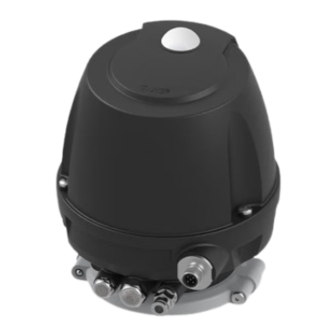
- Page 1 Translation from the original language Control and feedback systems GEA T.VIS® Q-15 GEA Tuchenhagen GmbH Document number: 430BAL015251 Version: 001 / Language: EN / Date: 18.03.2024 GEA.com PUBLIC...
- Page 2 EU Machinery Directive. This document is protected by copyright. All rights reserved. The document may not, in whole or in part, be copied, reproduced, translated or reduced to an electronic medium of machine-readable form without the express permission of GEA Tuchenhagen GmbH. LEGAL NOTICE Word marks ®...
- Page 3 TABLE OF CONTENTS General Information Information on the Document 1.1.1 Binding Character of These Operating Instructions 1.1.2 Notes on the Illustrations 1.1.3 Symbols and Highlighting Manufacturer address Contact EU Declaration of Conformity Translated copy of the EU Declaration of Conformity UK Declaration of Conformity in accordance with the regulations for electromagnetic compatibility 2016 Safety Intended use...
- Page 4 Carrying out a Reset – Back to Default Standard Decommissioning 12.1 Safety instructions 12.2 Disposal 12.2.1 General notes Spare parts list - control top T.VIS Q-15 Dimension sheet - control top T.VIS Q-15 Appendix 15.1 Lists 15.1.1 Abbreviations and terms 430BAL015251EN_2...
- Page 5 General Information Information on the Document General Information Information on the Document The present Operating Instructions are part of the user information for the product. The Operating Instructions contain all the information you need to transport, install, commission, operate and carry out maintenance for the product. 1.1.1 Binding Character of These Operating Instructions These Operating Instructions contain the manufacturer's instructions to the...
- Page 6 Second step in a sequence of operations. ® Result of the previous operation. ® The operation is complete, the goal has been achieved. Hint! Further useful information. Manufacturer address GEA Tuchenhagen GmbH Am Industriepark 2-10 21514 Büchen Contact Tel.:+49 4155 49-0 Fax:+49 4155 49-2035 flowcomponents@gea.com www.gea.com 430BAL015251EN_2 18.03.2024...
- Page 7 General Information EU Declaration of Conformity EU Declaration of Conformity EU Declaration of Conformity GEA Tuchenhagen GmbH Manufacturer Am Industriepark 2-10 21514 Büchen, Germany We hereby declare that the devices named below Model: Control Top T.VIS® Q-15 24V DC Type:...
- Page 8 General Information Translated copy of the EU Declaration of Conformity Translated copy of the EU Declaration of Conformity Manufacturer: GEA Tuchenhagen GmbH Am Industriepark 2-10 21514 Büchen, Germany We hereby declare that the devices named below Model: ® Control top T.VIS...
- Page 9 UK Declaration of Conformity in accordance with the regulations for electromagnetic compatibility 2016 UK- Declaration of Conformity by Electromagnetic Compatibility Regulations 2016 Manufacturer: GEA Tuchenhagen GmbH Am Industriepark 2-10 21514 Büchen, Germany Hereby, we declare that the machine designated in the following ®...
- Page 10 For overflow valves, the control top has an option for supplying the air externally via a hose. The control top T.VIS Q-15 may not be used in areas where ATEX approval is required.
- Page 11 EC Machinery Directive on your own. In general, only original spare parts supplied by GEA Tuchenhagen GmbH should be fitted. This ensures that the component is always operating properly and efficiently.
- Page 12 Safety General safety instructions and dangers • the component is used improperly • the component is operated under impermissible conditions 2.4.1 Principles for safe operation Dangerous situations during operation can be avoided by safety-conscious and proactive behaviour of the staff. To ensure safe operation of the valve the following principles apply: •...
- Page 13 Safety Supplementary Regulations • After completion of all work, check that the protective devices are fully functional. Supplementary Regulations In addition to the instructions in this documentation the following also has to be observed: • pertinent accident prevention regulations, • generally accepted safety rules, •...
- Page 14 Safety Safety equipment When working with the component, a distinction is made between the following user groups: User groups Staff Qualifications Operating personnel Adequate instruction and sound knowledge in the following areas: • Functionality of the component • Operating sequences on the pump •...
- Page 15 Safety Residual dangers Signs on the control top Sign Meaning General hazard warning Fig.1 Warning Crushing Fig.2 Residual dangers Dangerous situations can be avoided by safety-conscious and proactive behaviour of the personnel and by wearing personal protective equipment. Residual dangers on the control top and measures Danger Cause Measure...
- Page 16 Safety • In the event of malfunctions, shut down the control top (disconnect from the power and air supply) and secure it against being used. • Before starting any service, maintenance or repair work, disconnect the control top from the power supply and secure it against inadvertently being switched back on again.
- Page 17 3.1.2 Control top without solenoid valves The control top T.VIS Q-15 without solenoid valves acts as a position indicator. After programming, it indicates the status of the overflow valve locally by coloured LEDs under the illuminated dome so that it is visible over a long distance.
- Page 18 Description Functional description 3.1.3 Control Top with Solenoid Valves The control top with solenoid valves acts as a control top. The signalling takes place in the same way as with the control top without solenoid valves (position indicator). The difference is that the solenoid valve integrated in the base is operated in accordance with the control signals.
- Page 19 Description According to protection class IP67 and/or 69k (EN 60529) the control top T.VIS Q-15 is suitable for use in this design and if the electrical and pneumatic connections are installed correctly. To operate the control top, take off the cap and press the plus/minus buttons directly on the circuit board (A).
- Page 20 Transport and storage Storage conditions Transport and storage Storage conditions You must first dry and preserve the control top to prevent damage if the control top is exposed to temperatures ≤ 0°C during transport or storage. Hint! We recommend that the valve should be stored at a temperature of ≥ 5 °C for a period of 24 hours prior to any handling (disassembling the housings / activation of actuators) so that any ice crystals formed by condensation water can melt.
- Page 21 Explanation of the items in the order code Item in the Designation Explanation order code Feedback location T Q 1 5 Control top T.VIS Q-15 Control top type without solenoid valve 1 solenoid valve Y3=Lift valve disk 2 solenoid valves Y1 = D-force; Y3=Lift valve disk...
- Page 22 Technical data Type plate Explanation of the items in the order code Item in the Designation Explanation order code 8-pin connector M12 24 V DC for air hose Ø 6.35/4.31 mm (imperial) 5-pin connector M12 AS-interface 8-pin connector M12 24 V DC Options 5-pin M12 junction box for screw connection J, P (Material No.
- Page 23 Technical data Technical data Technical data Refer to the following tables for the key technical data of the control top: Technical data: compressed air supply, product pressure and CIP pressure Designation Description Air hose Material PE-LD Outside Ø 6 mm +/-0.1 mm •...
- Page 24 Technical data Specifications for 24V DC version Technical data: electrical specifications Designation Description Protection class EN 60529 IP66 - powerful water jet IP67 - immersion IP69 - high pressure EC EMC directives 2014/30/EU Immunity for industrial environments EN 61000-6-2: 2005 Radio frequency interference EN ISO 61000-6-4:2007 + A1: 2011 EC Low Voltage Directive...
- Page 25 Technical data Specifications for 24V DC version Technical data: outputs Designation Description Output voltage High = UV - ≤ 1 V Low = ≤ 5 V Max. current per output 100 mA short circuit proof Switching frequency 2 Hz (ohmic + inductive loads ≤ 25 mH) 430BAL015251EN_2 18.03.2024...
- Page 26 Technical data Specifications for AS-interface Specifications for AS-interface Technical data: supply Designation Description Supply voltage UV 26.5...31 V DC Current consumption - No-load current ≤ 25 mA - One solenoid valve incl. relay 60...70 mA function - Initiator 10 mA Total approx.
- Page 27 Technical data Accessories Technical data: electrical specifications Designation Description ASi specification V3.0 (A/B slave) Configuration 7.A.7.E. IO code / ID code / ID2 code Reverse voltage protection Accessories Accessories must be ordered separately. Accessories Part no. Cable socket, angular – M12; 5-pole: A coded 508-963 Cable socket, straight –...
- Page 28 Technical data Equipment Equipment Technical data - equipment Equipment Material no. Proximity switch M12x1 in the lantern • after NAMUR, normally open contact • 7.5...30 V DC 505-041 • Ambient temperature: -20...+70°C • Protection class IP 67 • metal-vaporized switching Solenoid valve •...
- Page 29 Assembly and installation Safety instructions Assembly and installation Safety instructions Hazardous situations during installation can be avoided by safety-conscious and proactive behaviour of the personnel. For installation, the following principles apply: • Only qualified personnel are allowed to set-up, install and commission the component.
- Page 30 Assembly and installation Pneumatic connection Pneumatic connection 6.3.1 Control top without solenoid valve Fig.8: Control top Safety ventilation against overpressure and exhaust air of the main stroke Y3 Non-return valve Connection E2 must not be closed! 430BAL015251EN_2 18.03.2024...
- Page 31 Assembly and installation Pneumatic connection 6.3.2 Control top with 1 solenoid valve (Y3) Fig.9 Safety ventilation against overpressure and exhaust air of the lifting stroke Y3 Non-return valve Connection E2 must not be closed! Central air supply with integrated filter Air connection for lifting stroke 430BAL015251EN_2 18.03.2024...
- Page 32 Assembly and installation Electrical connections 6.3.3 Control top with 2 solenoid valves (Y1 and Y3) Fig.10: Control top Ventilation D-force Y1 with sound absorber Connection E1 must not be closed! Safety ventilation against overpressure and exhaust air of the lifting stroke Y3 Non-return valve Connection E2 must not be closed!
- Page 33 Assembly and installation Electrical connections 6.4.1 Overview Fig.11 Danger Only allow properly qualified staff to carry out work on the electrical equipment. Prior to establishing electrical connections check the maximum permissible operating voltage. ► Hint! The cables must be suitable for use in the temperature range from -20 °C to 75 °C! 430BAL015251EN_2 18.03.2024...
- Page 34 Assembly and installation Electrical connections 6.4.2 Electrical 24 V DC Wiring 6.4.2.1 Connector M12 / 8-pin (24.1) Fig.12: 8-pin M12 plug-in connector A-coded: device connector and view of pin strip Corresponding cable socket part no. 508-061. L+24V DC supply voltage Signal downforce active L- reference potential Signal downforce inactive...
- Page 35 Assembly and installation Electrical connections 6.4.3.1 Plug M12 / 5-pin (24.1) Fig.13: 5-pin M12 plug-in connector A-coded: device connector and view of pin strip Associated cable sockets part 508-027, 508-028 and 508-963. AS-I+ Not connected AS-I- Not connected Not connected Carry out the following steps: Connect cable via air connector M12/5-pin.
- Page 36 Assembly and installation Electrical connections Caution! Only use proximity switches specified in the chapter "Technical data", see Chapter 5, Page 21. ► The use of a different initiator leads to no feedback being sent. Carry out the following steps: Insert the cable (Ø 3-7mm) through the cable gland (50) and connect it to the terminal (K1) according to the connection diagram.
- Page 37 Assembly and installation Electrical connections 6.4.4 Connection diagram for T.VIS circuit board (bottom) 24V DC Fig.15 AS-interface Fig.16 430BAL015251EN_2 18.03.2024...
- Page 38 Assembly and installation Electrical connections Explanation of the connection assignment (221-005021 and 221-005022) Connector Connector type Item no. in the Spare Parts Designation position List PicoBlade 5-pin 24.1(only for printed circuit Connector M12/3 board 24VDC) 24.2(only for printed circuit board ASi) PicoBlade 5-pin 24.1 Connector M12/3 (only with 221-005021)
- Page 39 Assembly and installation Visual Display Visual Display 6.5.1 Illuminated dome Fig.17 Illuminated dome The following statuses are visualized by the illuminated dome: • Valve in non-actuated position: green, see also Section 6.5.2, Page 40 • Downforce activated: yellow, see also Section 6.5.2, Page 40 •...
- Page 40 Assembly and installation Installation of the control top on overflow valves 6.5.2 Colour Changeover The "colour changeover" function allows you to swap the colour (from green to yellow or yellow to green) for the following visualizations: valve in non-actuated position, downforce activated, lift. Carry out the following steps: Disconnect the control top from the power supply.
- Page 41 Assembly and installation Installation of the control top on overflow valves Fig.18 Requirement: • Pay attention not to kink the air hoses when mounting the control top. Carry out the following steps: In order to mount the installation base T.VIS on the Q-valve, the pin screw (S) must be screwed completely out of the valve.
- Page 42 Assembly and installation Tighten the installation base using a face spanner. Fit the control top (B) over the pin screw (S) on the actuator (A.1). Tighten the clamps (15) and screws (39) to a torque of 1Nm (0.7 lbft). Align the pneumatic and electrical connections in accordance with the valve block configuration.
- Page 43 Start-up Safety precautions Start-up Safety precautions Initial commissioning For initial commissioning, the following principles apply: • Take protective measures against dangerous contact voltages in accordance with pertinent regulations. • The control top must be completely assembled and correctly adjusted. All screw connections must be securely tightened.
- Page 44 Start-up Commissioning – Control Top with Solenoid Valves Fig.20 Switch on the power supply. ® Only with reset: Activate programming mode by key operation, see Section 8.2, Page 50. ® Only with reset: Programming mode runs through automatically and during this time the illuminated dome is lit red.
- Page 45 Start-up Commissioning – Control Top with Solenoid Valves ® Switch on the solenoid valves in sequence Y3 and Y1 (if fitted) one after the other by means of the manual operating element: Turn the screw (S) from 0 to 1 using a screwdriver. ®...
- Page 46 Start-up Fitting the initiator in the lantern Hint! The solenoid valve Y1 (D-force) can also be activated and deactivated in manual mode using the operating buttons. Fitting the initiator in the lantern Fitting the initiator holder Carry out the following steps: Preassemble sliding piece (1), countersunk screw (3) and nut NI (2).
- Page 47 Start-up Fitting the initiator in the lantern Turn the nut NI (2) in the slot (4.1) in the lantern through 90° and tighten with the countersunk screw (3). Fig.26 ® Done. Adjusting the proximity switch holder Carry out the following steps: Screw the initiator (6) into the initiator holder down to the counter nut collar (7).
- Page 48 Start-up Fitting the initiator in the lantern Fig.27 Fig.28 430BAL015251EN_2 18.03.2024...
- Page 49 Start-up By slightly loosening the countersunk screw, position the initiator holder in the slotted hole of the lantern in such a way that the initiator (6) detects the lower edge of the counter nut. In operating state (non-actuated position) and following correct initiator setting, the LED on the initiator must be lit.
- Page 50 This allows user-specific process sequences to be optimally set. For the reliable monitoring of the valve seat seal GEA Tuchenhagen recommends the factory setting without signal attenuation. GEA Tuchenhagen will not accept any liability for damage resulting from the use of signal attenuation.
- Page 51 Operation and control Operating Overview Operating Overview Initial situation: T.VIS de‐energised! First commissioning before delivery or after Reset Initial/re‐commissioning on site Service Dis‐/Assembling (programmed; push buttons are locked 30s after power (not programmed; (push buttons automatically locked after SETUP) Störung detektiert Störung detektiert Mounting of valve insert Decision: Use according product code? (only TA15) Decision: New SETUP necessary? press and hold Power up Power up Power up Power up Power up Betriebsspannung Ein Betriebsspannung Ein Activation of main stroke to eliminate spring force. Default standard Attention! 3x red flashing/Pause If power will be switched off the valve disk will return ‐ ‐ to the start position because press for 3…7s press for 3…7s of spring force. Programming mode Operation mode color selection green = 500ms one‐time green flashing...
- Page 52 Operation and control Fig.30 430BAL015251EN_2 18.03.2024...
- Page 53 Cleaning Cleaning Cleaning Cleaning Observe the safety data sheets supplied by the detergent manufacturers. Only use detergents which are not aggressive towards synthetic materials and the sealing materials used and which are non-abrasive. Hint! After all cleaning work, make sure that the control top still complies with all safety instructions in this operating manual and thus that intended use is still given.
- Page 54 Maintenance Safety precautions Maintenance 10.1 Safety precautions Repair Before carrying out repair work on the component's electrical equipment, perform the following steps in accordance with the "5 safety rules": • Isolate from the power supply • Take appropriate measures to prevent switch on •...
- Page 55 Maintenance Inspections • Mark the lines (if unmarked) prior to disassembly to ensure they are not confused when re-assembling. • Protect open line ends with blind plugs against ingress of dirt. • Pack sensitive parts separately. • For longer periods of standstill, observe the storage conditions, see . 10.2 Inspections Checking parts are firmly secured...
- Page 56 Maintenance Maintenance intervals 10.3 Maintenance intervals To ensure the highest operational reliability of the magnetic separator, all wearing parts should be replaced at longer intervals. The actual maintenance intervals can only be determined by the user since they depend on the operating conditions, for instance: •...
- Page 57 Maintenance Dismantling the Control Top into its Components • Make sure that the solenoid valve is not actuated. Carry out the following steps: Undo the screw connection (39). Remove the clamp (15). Pull the control top vertically off the valve. Disconnect the M12 connectors connected electrically to the control top.
- Page 58 Maintenance Dismantling the Control Top into its Components 10.5.2 Removing the Cap Fig.33 Notice Electrical voltage Danger to life ► Switch off the voltage supply and the control air before removing the control top. Carry out the following steps: Undo the 3 screws (25) of the cap (7) and remove the cap (7) from the base (5).
- Page 59 Maintenance Dismantling the Control Top into its Components Fig.34 Remove all wires from printed circuit board (43) and printed circuit board (78.2). ® Done Hint! In order to avoid or minimize the possibility of damage from electrostatic discharge: – Observe the requirements of DIN EN 61340-5-1 and 5-2. –...
- Page 60 Maintenance Dismantling the Control Top into its Components Fig.35 Lift the printed circuit board bracket (9) off the basic plate. ® Done 10.5.6 Removing the Solenoid Valves and the Valve Plate Fig.36 Requirement: • Pay attention to the correct assignment of cables between the solenoid valves and the printed circuit board (78.1) (see Fig.
- Page 61 Maintenance Dismantling the Control Top into its Components • Use only solenoid valves as listed in the chapter "Technical data", see Chapter 5, Page 21. Warning! Long switch-on time and high ambient temperature. Risk of burns from the solenoid valve ►...
- Page 62 Maintenance Dismantling the Control Top into its Components • If only O-rings (42) and (55) are to be changed, solenoid valves (63)/valve plate (65) can remain on the pneumatic block (8). Carry out the following steps: Undo the screws (57.1, 57.2). Fig.38 Pull off the pneumatic block (8).
- Page 63 Maintenance Dismantling the Control Top into its Components Fig.39: Pneumatic block (8.2) for max. 1 solenoid valve Fig.40: Pneumatic block (8) for max. 3 solenoid valves Tighten the screw (57.2): tightening torque: 1.5 Nm (1.0 lbft). For the other parts to be fitted (sensor, printed circuit board, solenoid valves, valve plate) refer to the preceding pages.
- Page 64 Maintenance Install pneumatic connections 10.6 Install pneumatic connections Fig.41 Designation Tightening torques Screw-in plug connection 2.0 Nm Sound absorber 2.0 Nm Locking screw 0.5 Nm Plug Sound absorber 2.0 Nm O-ring Carry out the following steps: Establish the pneumatic connections in accordance with the codes on the control top.
- Page 65 Maintenance Maintenance 10.7 Maintenance 10.7.1 Replacing the Seals on the Base Fig.42 Carry out the following steps: Remove the O-rings (31, 54) and replace. ® Done 10.7.2 Servicing sound absorbers, filter, reflux valve 430BAL015251EN_2 18.03.2024...
- Page 66 Maintenance Maintenance Fig.43 Requirement: • Only use sound absorbers (26) specified in the spare parts list, see Chapter 13, Page 71. Carry out the following steps: Check the sound absorber (21, 26), reflux valve (26.1), filter (5.1) for free control air leakage and replace if necessary. ! The non-return valve (26.1) cannot be replaced.
- Page 67 Maintenance Fig.44 Carry out the following steps: Use three screws (25) to fasten the hood (7) on the base (5) to tightening torque 2 Nm. ® Done 430BAL015251EN_2 18.03.2024...
- Page 68 Alarms Malfunctions and remedies Alarms 11.1 Malfunctions and remedies In the event of malfunctions, immediately deactivate the valve and secure it against inadvertent reactivation. Malfunctions may only be remedied by qualified staff, who must observe the safety precautions. Malfunction, signalling, cause, remedy Malfunction Signalling Cause...
- Page 69 Carrying out a Reset – Back to Default Standard Malfunction, signalling, cause, remedy Malfunction Signalling Cause Remedy No feedback signal is Red LED flashing T.VIS Q-15 in factory Programming pending at the PLC setting and not yet according to although one of the programmed Operating overview, end positions has see Section 8.3,...
- Page 70 Decommissioning Safety instructions Decommissioning 12.1 Safety instructions For shutting down, the following principles apply: • Switch off the compressed air. • Switch off the component with the main switch. • Padlock the main switch (if fitted) in the off position to prevent it from being switched back on.
- Page 71 Spare parts list - control top T.VIS Q-15 Spare parts list - control top T.VIS Q-15 Fig.45 430BAL015251EN_2 18.03.2024...
- Page 72 Spare parts list - control top T.VIS Q-15 Control top T.VIS® Q-15 with cable connection and air connection with metric connections Order code TQ15N...M TQ15P...M TQ15J...M Item Designation Material Base T.VIS-T18 PA12/L 221-646.100 221-646.100 221-646.100 Filter 221-003869 221-003.869 221-003869 Screw-in plug connection D 6.0...
- Page 73 Spare parts list - control top T.VIS Q-15 Control top T.VIS® Q-15 with cable connection and air connection with imperial connections Order code TQ15N...Z TQ15P...Z TQ15J...Z Item Designation Material Base T.VIS-T18 PA12/L 221-646.100 221-646.100 221-646.100 Filter 221-003869 221-003.869 221-003869 Screw-in plug connection D 6.35...
- Page 74 Spare parts list - control top T.VIS Q-15 Control top T.VIS® Q-15 with metric cable connection and air connection with imperial connections Order code TQ15N...Z TQ15P...Z TQ15J...Z Item Designation Material Base T.VIS-T18 PA12/L 221-646.100 221-646.100 221-646.100 Filter 221-003869 221-003.869 221-003869 Screw-in plug connection D 6.35...
- Page 75 Spare parts list - control top T.VIS Q-15 Item Designation Material Material no. 24.1 Brass/ 221-005.102 Cable connection 24VDC M12/8-pole/A-coded Connector M12/8-pin/ nickel- M20x1.5 plated 24.2 Connector M12/5-pole/ Brass/ 221-005.101 Cable socket, ASi, M12/5-pole/A coded nickel- 5-wire/M20x1.5 plated Accessories (to be ordered separately) Material no.
- Page 76 Dimension sheet - control top T.VIS Q-15 Dimension sheet - control top T.VIS Q-15 Fig.46 For assignment of Y1, Y3, E1, E2 and P refer to the operating instructions for control top T.VIS Q-15 430BAL015251EN_2 18.03.2024...
- Page 77 Dimension sheet - control top T.VIS Q-15 X= supply voltage, electric actuation and feedback S3 = electrical connection for external proximity switch 430BAL015251EN_2 18.03.2024...
- Page 78 Appendix Lists Appendix 15.1 Lists 15.1.1 Abbreviations and terms Abbreviation Explanation British Standard Unit of measurement of pressure [bar] All pressure data expressed in [bar/psi] is assumed to be gauge pressure [barg/psig] unless explicitly specified otherwise. approx. approximately °C Unit of measurement of temperature [degree Celsius] Unit of measurement of volume [cubic decimetre] Standard volume (standard litre) DIN nominal width...
- Page 79 Appendix Abbreviation Explanation Metric Unit of measurement of work [newton metre] Specification of torque 1 Nm = 0.737 lbft Pound-Force (lb) + Feet (ft) Polyamide PE-LD Low-density polyethylene Polytetrafluoroethylene America measurement for pressure [Pound-forse per square inch] All pressure data expressed in [bar/psi] is assumed to be gauge pressure [barg/psig] unless explicitly specified otherwise.
Need help?
Do you have a question about the T.VIS Q-15 and is the answer not in the manual?
Questions and answers