GEA Tilting 3-point hitch Super Pump Instruction Manual And Installation Instructions
Pto pumps
Hide thumbs
Also See for Tilting 3-point hitch Super Pump:

Related Manuals for GEA Tilting 3-point hitch Super Pump


Summary of Contents for GEA Tilting 3-point hitch Super Pump
- Page 1 Tilting 3-point hitch Super_Pump PTO pumps Instruction Manual / Installation Instructions (Original instructions) 2010-9015-004 03-2014 engineering for a better world GEA Farm Technologies...
-
Page 2: Table Of Contents
................GEA Houle Inc. - General Equipment Warranty . - Page 3 Operation ..............Special personnel qualification required for operation .
-
Page 4: Preface
Preface Information on the instructions Preface Information on the instructions The manufacturer reserves the right to make changes due to technical developments in the data and images given in this manual. Reproductions, translations and copies of any kind, even of extracts, require written authorization from the manufacturer. -
Page 5: Manufacturer Address
Preface Customer services Manufacturer address GEA Farm Technologies Canada Inc. / Division GEA Houle 4591 boul. St-Joseph Drummondville, Qc, J2A 0C6 +1 819 477 - 7444 +1 819 477 - 5565 geahoule@gea.com www.gea-farmtechnologies.com Customer services authorized Technical Dealer If necessary, please contact your nearest authorized technical dealer. -
Page 6: Declaration Of Conformity
The undersigned is acting by virtue of power of attorney from the management of: GEA Farm Technologies Canada Inc. / Division GEA Houle, 4591 boul. St-Joseph, Drummondville, Qc, J2A 0C6 This declaration certifies compliance with the guidelines indicated, but does not establish any guarantee in the sense of paragraphs 443, 444 of the BGB. -
Page 7: Gea Houle Inc. - General Equipment Warranty
1.5.1 Limited warranty GEA Houle Inc. (hereinafter referred to as ”the Company”) warrants to the original buyer and end user (hereinafter referred to as the ”Purchaser”) that the parts of all equipment sold under the Company trademark are free from defects in material or workmanship for a period of twelve (12) months from the date of delivery of the equipment to the Purchaser. - Page 8 Preface GEA Houle Inc. - General Equipment Warranty 1.5.3 Extent of limited warranty This limited warranty DOES NOT cover: ● Defects caused by negligence of the Purchaser in the maintenance of the equipment, improper use resulting from failure to adhere strictly to the...
- Page 9 Preface GEA Houle Inc. - General Equipment Warranty 1.5.4 Warranty limitations and exclusion NO WARRANTY, ORAL OR WRITTEN, EXPRESS OR IMPLIED, OTHER THAN THE ABOVE WARRANTY IS PROVIDED IN RESPECT OF THE EQUIPMENT SOLD. Some states (or jurisdictions) do not allow the exclusion of implied warranties so it is possible that this limitation may not apply.
-
Page 10: Safety
Safety Owner's obligation of care Safety Owner's obligation of care The product has been designed and constructed while taking account of a potential risk analysis and after careful selection of the harmonized standards and other technical specifications to be complied with. It therefore guarantees a maximum level of safety. -
Page 11: Explanation Of The Safety Symbols Used
Safety Explanation of the safety symbols used ● Escape routes are marked by means of signs in accordance with national regulations! ● The personal protective equipment required for personnel carrying out operation, maintenance and repairs is made available and used. ●... -
Page 12: Basic Safety Instructions
Safety Personnel qualification Basic safety instructions Note! There are warnings about specific residual dangers in the corresponding chapters. Note! If the work requires special qualifications, these are described in the corresponding chapters! ● There are risks involved in the operation and maintenance of equipment for dairy farms. -
Page 13: Protective Devices
Safety Protective devices Protective devices ● Protective devices Protective guard for power take off driveline (part no. 2010-7600-960) European Safety cap (part no. 2010-7704-670) ● Safety symbols, warnings, warning signs and labels Danger! - Toxic gases (American model) Manure produces toxic gases that can cause loss of consciousness, asphyxia or death in few seconds. - Page 14 Safety Protective devices Warning! (European model) (part no. 2099-4725-200) Warning! (European model) Read the instruction manual before operating, maintenance. (part no. 2099-4725-130) Maximum 540 RPM (part no. 2010-4703-430) Maximum 1000 RPM (part no. 2010-4703-440) 2010-9015-004 14 / 76 03-2014...
-
Page 15: Description
Any unauthorized modifications to the product will invalidate the warranty and may invalidate the provided manufacturer's declaration or installation declaration. Parts and special equipment which have been obtained elsewhere must be expressly authorized by GEA Houle, in writing, for use in GEA Houle components and installations. 2010-9015-004 15 / 76... -
Page 16: Design Of The Equipment
Functional description Design of the equipment Design The Tilting 3-point hitch Super Pump consists of: ● a vertical pump fixed on a 3-point hitch on a farm tractor. ● an adjustable nozzle to homogenize manure. ● a directional valve to divert the flow to either the agitation nozzle or the discharge line. -
Page 17: Technical Data
Description Technical Data Technical Data Performance data 6” Super pump with impeller 20” x 6 blades and 12” intake. Shut-off RPM/ ratio Nozzle diameter Nozzle pressure Maximum head* pressure 540 / +10% 3” [76 mm] 20 psi [1.4 bar] 22 psi [1.5 bar] 36 ft [11.0 m] 540/ +26% 3”... - Page 18 Description Technical Data Hydraulic hoses I.D. ¼” ½” ¾” O.D. 0.58” 0.86” 1.10” Quantity of braids 400 bar 276 bar 105 bar Service pressure (5,800 psi) (4,000 psi) (1,525 psi) -40ºC - 100ºC Service temperature (-40ºF - 212ºF) 2010-9015-004 18 / 76 03-2014...
-
Page 19: Total Pumping Head Formula
Description Total Pumping Head Formula Total Pumping Head Formula 3.6.1 S.A.E. Example Refer to Appendix: Pumping Head Calculation to correctly fill the formula. ● Determine the Wanted Transfer rate. ● Execute the manure Consistency Test. ● Sketch the Transfer Line with all lengths, diameters, elbows valves, adaptors material type and elevation like the example below. - Page 20 Description Total Pumping Head Formula 3.6.2 Metric Example Refer to Appendix: Pumping Head calculation to correctly fill the formula. ● Determine the Wanted Transfer rate. ● Execute the manure Consistency Test. ● Sketch the Transfer Line with all lengths, diameters, elbows valves, adaptors material type and elevation like the example below.
-
Page 21: Main View
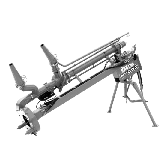
Description Main view Main view Standard handle* (Handle rotating the agitation nozzle*) Agitation / loading indicator rod Up = loading Down = agitation Agitation nozzle Oil cooler Gearbox Directional valve Bearing housing grease lines Main frame Directional valve cover Directional valve cylinder Access to driveline joint Drain (access to bearing housing) Handle operating the agitation nozzle... -
Page 22: Options
Description Options Options Gear reducer to rotate the agitation nozzle Gear reducer Handle Safety lock Hydraulic controls Hydraulic motor operating the agitation nozzle rotation Hydraulic cylinder Hydraulic control valves operating the agitation nozzle up and down Directional valve agitation or loading 2010-9015-004 22 / 76 03-2014... - Page 23 Description Options 2nd. Agitation nozzle Hydraulic cap 2nd. Agitation nozzle 2010-9015-004 23 / 76 03-2014...
-
Page 24: Transport
Transport Safety instructions for transport Transport Special personnel qualification required for transport Transport may only be performed by specially qualified personnel in accordance with the safety instructions. ● National driver's licence for drive-on machines, stackers and other trucks. Also see the section on ”Personnel qualification”. Safety instructions for transport To prevent damage to property and/or life-threatening injury to personnel always observe the following:... -
Page 25: Permissible Devices And Aids For Transportation
Transport Permissible devices and aids for transportation Permissible devices and aids for transportation The Pump is made up of heavy components. Loading and unloading Appropriate lifting gear and carrying devices such as, chain hoist, safety chain, fork lift truck or front loader is to be provided. Fork lift truck Safety Chain Crane... -
Page 26: Transport
Transport Information on disposing of packing material Transport Attention! Moving the pump The pump must be moved on a tractor 3-point hitch with a minimum capacity of; 6,000 lb [2700 kg] Make sure that both the tilting 3-point hitch cylinder and the tractor hydraulic circuit have enough oil to safely raise and lower the pump. -
Page 27: Installation
Installation Safety instructions for installation Installation If necessary, please contact your nearest authorized technical dealer. Special personnel qualification required for installation Installation may only be carried out by specially qualified personnel in accordance with the safety instructions. Also see the section on ”Personnel qualification”. Safety instructions for installation Warning! Read Instructions First! To prevent serious injury or death, do not... -
Page 28: Assembly Preparations
Installation Assembly preparations Assembly preparations Special tools Attention! To lift the pump and steady in place when assembling, use a lifting device with a minimum capacity of; 1,300 lb [600 kg]. Fork lift truck Safety Chain Crane Front end loader 2010-9015-004 28 / 76 03-2014... -
Page 29: Pump Assembly
Installation Pump assembly Pump assembly Agitation nozzle ● Install the nozzle on the directional Safety bolt valve. ● Point the nozzle towards the ground. Reducer ● Install the circle lock and tighten the safety bolt to secure the nozzle; ● If required, install the reducer at the Circle tip of the nozzle. - Page 30 Installation Pump assembly Tilting 3-point hitch ● Hook the lifting device to the lifting Lifting ring ring of the pump. Cylinder of the ● Lift the top of the pump. 3-point hitch ● Bolt the tilting 3-point hitch to the main frame.
-
Page 31: Information On Disposing Of Installation Material After Installation Is Finished
Installation Information on disposing of installation material after installation is finished. Information on disposing of installation material after installation is finished. Handle unused installation material properly and dispose in accordance with current valid local regulations on waste disposal and utilization. 2010-9015-004 31 / 76 03-2014... -
Page 32: Initial Commissioning
Initial Commissioning Safety instructions for initial commissioning Initial Commissioning Special personnel qualification required for initial commissioning Initial commissioning may only be performed by specially qualified personnel in accordance with the safety instructions. Also see the section on ”Personnel qualification”. Safety instructions for initial commissioning Warning! Read Instructions First! To prevent serious injury or death, do not operate or service this machine without first reading and... -
Page 33: Checks Before Initial Commissioning
Initial Commissioning Checks before initial commissioning Checks before initial commissioning The owner should ensure that: ● Oil in the oil tank is at proper level. - Add SAE 80W90 gear oil if necessary. ● All grease zerk have been lubricated. ●... -
Page 34: First Start
Initial Commissioning Checks after initial commissioning First start Danger! Manure produces toxic gases that can cause a loss of conciousness, asphyxia or death in a few seconds. Manure agitation can produce toxic gases in buildings built above the pit. Toxic gases can also emanate in buildings situated by the pit and / or connected to the pit by an evacuation line. -
Page 35: Handing Over To The Owner
Initial Commissioning Handing over to the owner Handing over to the owner Declaration of conformity and CE mark (only necessary for European Union member states) A declaration of conformity must be produced and a CE mark applied if a total operational installation is assembled from individual components. -
Page 36: Operation
Operation Safety instructions for operation Operation Special personnel qualification required for operation Operation may only be performed by specially qualified personnel in accordance with the safety instructions. Also see the section on ”Personnel qualification”. Safety instructions for operation Warning! Read Instructions First! To prevent serious injury or death, do not operate or service this machine without first reading and understanding the operator's manuals for all of the equipment. - Page 37 Operation Safety instructions for operation Before operating, make sure you are adequately familiar with the following: ● the operating and control elements ● the equipment ● The method of operation ● The immediate environment ● The safety devices Danger! Manure produces toxic gases that can cause a loss of conciousness, asphyxia or death in a few seconds.
- Page 38 Operation Safety instructions for operation In normal operation: ● The product may only be started from the location specified. ● During operation, operating personnel may only stand at the specified workplaces. See section on ”Workplaces for operating personnel” ● No safety equipment may be removed or put out of operation during operation.
- Page 39 Operation Safety instructions for operation PTO driveline Maximum Extension and Retraction ● While operating the pump, never exceed the maximum points indicated by the adhesive tapes on the male guard. ● The minimum retraction indicator must never disappear underneath the female guard. ●...
-
Page 40: Workplaces For Operating Personnel
Operation Workplaces for operating personnel Workplaces for operating personnel Danger! Manure produces toxic gases that can cause a loss of conciousness, asphyxia or death in a few seconds. Manure agitation can produce toxic gases in buildings built above the pit. Toxic gases can also emanate in buildings situated by the pit and / or connected to the pit by an evacuation line. -
Page 41: Description Of The Operating Elements
Operation Description of the operating elements Description of the operating elements 7.4.1 Manual controls Nozzle rotation Nozzle up and down ● To rotate the nozzle CW turn the handle CCW. ● To rotate the nozzle CCW turn the Nozzle handle CW. rotation Nozzle rotation ●... - Page 42 Operation Description of the operating elements 7.4.2 Hydraulic controls (optional) Agitation nozzle rotation Agitation nozzle up and down Hydraulic control valves Directional valve agitation or loading Agitation nozzle up / down Agitation nozzle rotation Hydraulic cap on agitation nozzle Directional valve agitation/ loading 2010-9015-004 42 / 76 03-2014...
- Page 43 Operation Description of the operating elements Circle lock cap on discharge pipe If the transfer hose is not connected, install the circle lock on discharge pipe. Warning! Never unlock a circle lock cap under pressure! Unlocking a circle lock cap under pressure could cause serious injuries to anyone standing near the cap.
-
Page 44: Operating
Operation Operating Operating Danger! Manure produces toxic gases that can cause a loss of conciousness, asphyxia or death in a few seconds. Manure agitation can produce toxic gases in buildings built above the pit. Toxic gases can also emanate in buildings situated by the pit and / or connected to the pit by an evacuation line. - Page 45 Operation Operating 7.5.1 Moving the pump Attention! Moving the pump The pump must be moved on a tractor 3-point hitch with a minimum capacity of; 6,000 lb [2700 kg] Make sure that both the tilting 3-point hitch cylinder and the tractor hydraulic circuit have enough oil to safely raise and lower the pump.
- Page 46 Operation Operating ● To raise the pump to the maximum, gradually lift the tractor 3-point hitch while closing the cylinder of the tilting 3-point hitch. ● Remove the storage legs. ● Before moving, shut off the safety valves of the tilting 3-point hitch cylinder. 2010-9015-004 46 / 76 03-2014...
- Page 47 Operation Operating 7.5.2 Positioning the pump Note! To speed up the agitation time, it is recommended to install the pump in liquid near solid masses. ● Open the safety valves of the tilting Keep the 3-point hitch 3-point hitch; cylinder under tension ●...
- Page 48 Operation Operating 7.5.3 Agitation mode Danger! Rotating driveline keep away! Turn off the tractor before installing or removing the PTO driveline. Attention! The safety valves of the 3-point hitch cylinder must be shut off when agitating and transferring manure. Note! The hydraulic cap on the bottom nozzle may be used to shut off flow to bottom nozzle and therefore increase pressure and flow to the top nozzle.
- Page 49 Operation Operating 7.5.4 Manure transfer mode Danger! Rotating driveline keep away! Turn off the tractor before installing or removing the PTO driveline. Attention! The safety valves of the 3-point hitch cylinder must be shut off when agitating and transferring manure. Note! Thoroughly agitate the content of the reservoir before transferring the manure.
- Page 50 Operation Operating Compressed air under the circle lock cap If the directional valve changes position while agitating a pit, the impeller of the pump will force manure into the discharge pipe, compressing the air inside the pipe. ● Remove the cap of the discharge pipe; ●...
- Page 51 Operation Operating 7.5.5 Removing the pump from the tank Danger! Rotating driveline keep away! Turn off the tractor before installing or removing the PTO driveline. ● Remove the PTO driveline. ● Open the safety valves of the tilting 3-point hitch. ●...
-
Page 52: Operating Faults
Operating faults Safety instructions for troubleshooting Operating faults If necessary, please contact your nearest authorized technical dealer. Special personnel qualification required for troubleshooting Troubleshooting may only be performed by specially qualified personnel in accordance with the safety instructions. Also see the section on ”Personnel qualification”. Safety instructions for troubleshooting Warning! Read Instructions First! To prevent serious injury or death, do not... - Page 53 Operating faults Safety instructions for troubleshooting Special dangers involved in troubleshooting: Danger! Manure produces toxic gases that can cause a loss of conciousness, asphyxia or death in a few seconds. Manure agitation can produce toxic gases in buildings built above the pit.
-
Page 54: Troubleshooting Possible Faults
Operating faults Troubleshooting possible faults Troubleshooting possible faults Symptom Possible cause Remedy Pump is not working Broken PTO shear bolts. Replace PTO shear bolts. properly or not at all. PTO driveline has a defective Inspect the drive line. joint or is disconnected. Broken shaft in drive line. -
Page 55: Maintenance
Maintenance Safety instructions for maintenance Maintenance If necessary, please contact your nearest authorized technical dealer. Special personnel qualification required for maintenance work Maintenance work may only be performed by specially qualified personnel in accordance with the safety instructions. Also see the section on ”Personnel qualification”. Safety instructions for maintenance Warning! Read Instructions First! To prevent serious injury or death, do not... - Page 56 Maintenance Safety instructions for maintenance Before carrying out any maintenance work, make sure of the following: ● The area for the maintenance work and access to the working area should be secured over a wide area and there should not be any unauthorized people in the working area.
- Page 57 Maintenance Safety instructions for maintenance After completing the maintenance work, check the following: ● The installation values set before the work are not altered by the work (report). ● Any screwed connections that were loosened earlier have been tightened. ● Any guards, cover, lids, sieves, filters, ... that were removed earlier have been put back again correctly.
-
Page 58: Inspections And Preventive Maintenance
Maintenance Inspections and preventive maintenance Inspections and preventive maintenance Lubrication Danger! Manure produces toxic gases that can cause a loss of conciousness, asphyxia or death in a few seconds. Manure agitation can produce toxic gases in buildings built above the pit. - Page 59 Maintenance Inspections and preventive maintenance 9.3.2 Every 5 hours Note! Use specified grease or equivalent: Red Texas 880 crown and chassis® grade 0 (2010-4300-790) 5 grease points on each joint ● Grease joints and sliding section of PTO driveline. On universal joints, use a high quality grease formulated...
- Page 60 Maintenance Inspections and preventive maintenance 9.3.5 Every 75 hours To change the oil of the pump main frame: Note! Use gearbox oil SAE 80W90. ● Remove the magnetic plug located Filling plug at the bottom of the oil cooler pipes. ●...
-
Page 61: Repairs
Maintenance Repairs Cleaning the pump Attention! Pressure washer may damage the paint if it is not used properly. Use pressure washer not exceeding 2000 psi [105 bar]. Only use cold water when cleaning with a pressure washer. Keep the pressure washer nozzle at least 1 ft [30 cm] from the surface to be cleaned. -
Page 62: Decommissioning
Decommissioning Safety instructions for decommissioning Decommissioning 10.1 Special personnel qualification required for decommissioning Decommissioning may only be performed by specially qualified personnel in accordance with the safety instructions. Also see the section on ”Personnel qualification”. 10.2 Safety instructions for decommissioning Warning! Read Instructions First! To prevent serious injury or death, do not operate or service this machine without first reading and... -
Page 63: Temporary Decommissioning
Decommissioning Temporary decommissioning 10.3 Temporary decommissioning Danger! Rotating driveline keep away! Turn off the tractor before lubricating or cleaning the pump. Storage ● Install the storage legs. ● Place the pump on a flat and firm surface. ● Remove the cover of the directional valve and clean the housing. Be sure to clean out any accumulation of dry manure;... -
Page 64: Final Decommissioning/Disposal
Decommissioning Final decommissioning/disposal ● Grease the driveline joints and all parts labeled with; Refer to section 11.1 Label position ● To prevent corrosion, spread a film of oil on all moving parts. 10.4 Final decommissioning/disposal After final decommissioning, handle all components properly and dispose of them in accordance with valid local regulations on waste disposal and utilization. -
Page 65: Appendix
Appendix Label position Appendix 11.1 Label position H, K 2010-9015-004 65 / 76 03-2014... - Page 66 Appendix Label position American European 2010-4700-400 2099-4720-010 2099-4725-210 2099-4725-100 2099-4720-020 2099-4725-400 2099-4720-070 2099-4725-130 2099-4725-200 2099-4721-020 2010-4701-590 2003-4701-240 2010-4703-790 2010-9015-004 66 / 76 03-2014...
- Page 67 Appendix Label position 2099-4725-310 2010-4703-381 2010-4703-430 2010-4703-440 2010-9015-004 67 / 76 03-2014...
-
Page 68: Abbreviations
Appendix Abbreviations 11.2 Abbreviations Units ° Degrees (angles) CE/ EC European Union Centimeters Clockwise Counterclockwise Gallon Horsepower ” (in) Inch (= 25.4 mm) Incorporated Kilograms km/h Kilometers per hour Left or liters Pounds Meter Millimeters Maximum Minimum Miles per hour National coarse thread Power take-off Quebec (Canada) -
Page 69: Pumping Head Calculation
Appendix 11.3 Pumping Head Calculation Note! Read the following information prior to calculate and fill the Total Pumping Head Formula. 11.3.1 Transfer rate ● In SAE, the Transfer Rate is expressed in US GPM. ● In Metric, the Transfer Rate is expressed in Liters per minute. 11.3.2 Difference in Elevation Determined by the height between the pump intake and the top of the storage pit. - Page 70 Appendix 11.3.5 Straight pipe equivalent for components To complete the total friction loss calculation, each elbow, adapter and valve must be converted into it's equivalent linear dimension of line and added to the length of line. Pipe Diameter S.A.E. METRIC Components 3”...
- Page 71 Appendix 11.3.6 Friction Loss Coefficient for PVC Pipes Consistency of Liquids and Manure PVC Pipes US Gallons Liters per Diameter per minute minute 1/8” 1/4” 1/2” 3/4” Water (3mm) (6mm) (12mm) (18mm) 0.0526 0.0599 0.0710 0.1041 0.1519 3” 0.0980 0.1117 0.1323 0.1940 0.2832...
- Page 72 Appendix 11.3.7 Friction Loss Coefficient for Flexible Hoses and Steel Pipes Consistency of Liquids and Manure PVC Pipes US Gallons Liters per Diameter per minute minute 1/8” 1/4” 1/2” 3/4” Water (3mm) (6mm) (12mm) (18mm) 0.0682 0.0777 0.0920 0.1350 0.1970 3”...
-
Page 73: Hydraulic Diagrams
Appendix Hydraulic diagrams 11.4 Hydraulic diagrams Hydraulic controls Note! The diagram illustrates all hydraulic controls available on the pump. The dashed frame shows a component equipped with a control lever. All components equipped with a control lever may be connected togheter using the same tractor outlet. A Directional valve cylinder B Nozzle height cylinder C Nozzle rotation motor... - Page 74 Appendix Hydraulic diagrams Cooling system Internal member (pump) Oil pump ¾” [19 mm] Cooling pipes 2010-9015-004 74 / 76 03-2014...
- Page 75 Appendix Hydraulic diagrams 2010-9015-004 75 / 76 03-2014...
- Page 76 Excellence • Passion • Integrity • Responsibility • GEA-versity GEA Group is a global engineering company with multi-billion euro sales and operations in more than 50 countries. Founded in 1881, the company is one of the largest providers of innovative equipment and process technology.
Need help?
Do you have a question about the Tilting 3-point hitch Super Pump and is the answer not in the manual?
Questions and answers
What is the role of tilting
The tilting function in the GEA Tilting 3-point hitch Super Pump allows the pump to be properly positioned and adjusted when lowered into the manure storage pit. It helps in agitating, homogenizing, and transferring manure efficiently. The tilting mechanism, controlled by hydraulic hoses connected to the tractor, enables better maneuverability and ensures optimal operation.
This answer is automatically generated