Table of Contents
Advertisement
Quick Links
One Technology Way • P.O. Box 9106 • Norwood, MA 02062-9106, U.S.A. • Tel: 781.329.4700 • Fax: 781.461.3113 • www.analog.com
AD8452
FEATURES
Fully functional Li-Ion cell formation and testing similar to
real-world manufacturing equipment
Ability to charge and discharge batteries under constant
current and constant voltage control
Energy recycling from discharging battery into a dc bus
Full featured system evaluation board based on the AD8452
PC software for control and monitoring of system
parameters
Compatible with the System Demonstration Platform,
SDP-S
(EVAL-SDP-CS1Z)
EVALUATION KIT CONTENTS
Analog interface board
Power module board (10 V to 20 V dc operating range)
SDP-S
board for data transfer to PC
Standard USB A to Mini-B USB cable
Printed user guide
Evaluation kit software CD
HARDWARE REQUIREMENTS
Bench power supply, 12 V to 24 V dc (current depending on
desired battery charge rate)
Test battery or electronic load
Windows PC with a USB port
WARNING
When testing this system with lithium-ion (Li-Ion) batteries,
take care not to overcharge or overdischarge the batteries, or to
sink/source more than the maximum current recommended by
the manufacturer of the battery. Exceeding these ratings can not
only damage the battery, but can also cause it to explode or
catch on fire.
PLEASE SEE THE LAST PAGE FOR AN IMPORTANT
WARNING AND LEGAL TERMS AND CONDITIONS.
Battery Testing and Formation Evaluation Board
Rev. 0 | Page 1 of 32
AD8452
System Demo User Guide
GENERAL DESCRIPTION
The AD8452 system demo evaluation kit is a recommended
starting point for users building battery formation and test
equipment based on the Analog Devices, Inc., AD8452 precision
analog front end and pulse-width modulation (PWM) controller.
The evaluation kit includes an analog interface board and a
power module board.
In addition to the AD8452, the analog interface board also includes
an
AD5689R
16-bit, precision digital-to-analog converter (DAC)
to set the current and voltage set points, and an
Σ-Δ analog-to-digital converter (ADC) to monitor the battery
voltage and current.
The analog interface board includes built-in voltage regulators
so that it can be powered either from the bus power inputs or
directly from a 15 V dc supply through a screw terminal connector.
The analog interface board connects to the Analog Devices System
Demonstration Platform (SDP-S) through a 120-pin connector.
The
SDP-S
board connects to the user interface software through
the USB port, allowing the user to set the current and voltage
set point as well as the mode of operation (charge or discharge).
In addition, the user can monitor the battery voltage and
current by reading the data output from the AD7173-8.
The analog interface board connects to the power module board
through three multipin headers. This modular approach allows
the user to design and test their own power module boards,
designed for the current output range in their end applications,
with the analog interface board of this reference design.
The standard power module board supports charge and discharge
currents of up to 10 A. It includes the power metal-oxide
semiconductor field effect transistors (MOSFETs), the inductor,
and the input and output capacitors required to implement a
buck or boost regulator, depending on the operating mode.
Full specifications of the AD8452 are available in the product data
sheet, which must be consulted in conjunction with this user guide
when working with the evaluation kit.
UG-1181
AD7173-8
24-bit,
Advertisement
Table of Contents

Related Manuals for Analog Devices AD8452


Summary of Contents for Analog Devices AD8452
-
Page 1: Features
The evaluation kit includes an analog interface board and a Full featured system evaluation board based on the AD8452 power module board. PC software for control and monitoring of system In addition to the AD8452, the analog interface board also includes parameters AD5689R 16-bit, precision digital-to-analog converter (DAC) -
Page 2: Table Of Contents
Setting Up the Evaluation System ..........5 Troubleshooting ................28 Powering the System ..............5 Software ..................28 AD8452 Compensation Networks ..........5 Hardware ..................28 Serial Interface ................5 Ordering Information ..............29 Power Module Board Description ..........6 Bill of Materials ................ -
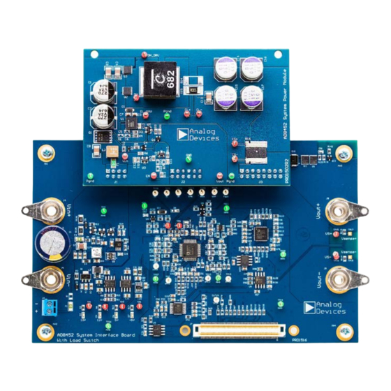
Page 3: Evaluation Board Photograph
AD8452 System Demo User Guide UG-1181 EVALUATION BOARD PHOTOGRAPH Figure 1. Power Module Board (Top), Analog Interface Board (Bottom) Rev. 0 | Page 3 of 32... -
Page 4: Simplified Evaluation Board Block Diagram
UG-1181 AD8452 System Demo User Guide SIMPLIFIED EVALUATION BOARD BLOCK DIAGRAM STD 12V POWER MODULE (10V TO 20V DC IN) FET DRIVER ENABLE ADuM7223 DH DL CL+ CL– CS+ CS– DC OUT DC IN (10V TO 30V) AUX POWER INTEGRATED ANALOG FRONT END,... -
Page 5: Evaluation Board Hardware
The analog interface board includes the AD8452 (U7), the in each of the four AD8452 control loops to ensure system AD7173-8 24-bit Σ-Δ ADC (U10), and the... -
Page 6: Power Module Board Description
The current sense programmable gain instrumentation amplifier second pair of load switch FETs. Current is forced through the (PGIA) of the AD8452 has a fixed gain of 66. With a gain of 66, a diode in parallel with the disabled FET pair, controlling the 10 A output current results in an output voltage of 1.98 V at TP6... -
Page 7: Evaluation Board Software
SDP-S board is recognized when it connects to the PC. Start the Windows® operating system and download the software from the AD8452 product page on the Analog Devices website. Unzip the downloaded file. Run the setup.exe file. After installation is complete, plug the... -
Page 8: Board Operation/Connection Sequence
Found Hardware Wizard to run. Check that the drivers and the board are connected correctly by looking at the Device Manager of the PC. The Analog Devices System Development Platform SDP-S appears under ADI Development Tools (see Figure 11). -
Page 9: Running The Software With The Hardware Connected
AD8452 System Demo User Guide UG-1181 RUNNING THE SOFTWARE WITH THE HARDWARE When the AD8452 analog interface board is detected, the message in Figure 13 displays. Click Select to continue. CONNECTED To run the program, take the following steps: Click Start, All Programs, Analog Devices, AD8452_SystemDemoBoard, AD8452_SystemDemoBoard. -
Page 10: Software Operation
MODE: CHARGE button indicates that the system is currently in charge mode. Clicking this button changes the power module configuration (and the text changes to MODE: DISCHARGE). Figure 14. AD8452 System Demo Board Software Main Window Rev. 0 | Page 10 of 32... - Page 11 AD8452 System Demo User Guide UG-1181 Figure 15. Software Main Window During Normal Operation Rev. 0 | Page 11 of 32...
-
Page 12: Configuration Tab
Nominally Scaled Measurement uses the typical values for programmable gain differential voltage sense amplifier. the sense resistor, the ADC reference, the AD8452 gain, and so on. The default is 0.4. Current Gain Correction is the gain correction constant for Full Scale Current is the setting to change the scaling of the the current measurement. -
Page 13: Evaluation Board Schematics-Power Module Board
AD8452 System Demo User Guide UG-1181 EVALUATION BOARD SCHEMATICS—POWER MODULE BOARD Figure 17. Power Module Schematic Rev. 0 | Page 13 of 32... - Page 14 UG-1181 AD8452 System Demo User Guide Figure 18. Power Module Board Top Silkscreen Figure 19. Power Module Board Top Layer Rev. 0 | Page 14 of 32...
- Page 15 AD8452 System Demo User Guide UG-1181 Figure 20. Power Module Board Layer 2 Figure 21. Power Module Board Layer 3 Rev. 0 | Page 15 of 32...
- Page 16 UG-1181 AD8452 System Demo User Guide Figure 22. Power Module Board Bottom Layer Figure 23. Power Module Board Bottom Silkscreen Rev. 0 | Page 16 of 32...
- Page 17 AD8452 System Demo User Guide UG-1181 Figure 24. Power Module Board Rev. 0 | Page 17 of 32...
-
Page 18: Evaluation Board Schematics-Analog Interface Board
UG-1181 AD8452 System Demo User Guide EVALUATION BOARD SCHEMATICS—ANALOG INTERFACE BOARD Figure 25. Power Module Connectors and Auxiliary Power Supplies Rev. 0 | Page 18 of 32... - Page 19 AD8452 System Demo User Guide UG-1181 Figure 26. AD8452 and Compensation Networks Rev. 0 | Page 19 of 32...
- Page 20 UG-1181 AD8452 System Demo User Guide Figure 27. ADC, DAC, and SDP Connector Rev. 0 | Page 20 of 32...
- Page 21 AD8452 System Demo User Guide UG-1181 Figure 28. Analog Interface Board Top Silkscreen Rev. 0 | Page 21 of 32...
- Page 22 UG-1181 AD8452 System Demo User Guide Figure 29. Analog Interface Board Top Layer Rev. 0 | Page 22 of 32...
- Page 23 AD8452 System Demo User Guide UG-1181 Figure 30. Analog Interface Board Layer 2 Rev. 0 | Page 23 of 32...
- Page 24 UG-1181 AD8452 System Demo User Guide Figure 31. Analog Interface Board Layer 3 Rev. 0 | Page 24 of 32...
- Page 25 AD8452 System Demo User Guide UG-1181 Figure 32. Analog Interface Board Bottom Layer Rev. 0 | Page 25 of 32...
- Page 26 UG-1181 AD8452 System Demo User Guide Figure 33. Analog Interface Board Bottom Silkscreen Rev. 0 | Page 26 of 32...
- Page 27 AD8452 System Demo User Guide UG-1181 Figure 34. Analog Interface Board Rev. 0 | Page 27 of 32...
-
Page 28: Troubleshooting
UG-1181 AD8452 System Demo User Guide TROUBLESHOOTING SOFTWARE HARDWARE To troubleshoot the software, take the following steps: To troubleshoot the hardware, take the following steps: Always install the software prior to connecting the If the software does not read any data back, check that the hardware to the PC. -
Page 29: Ordering Information
AD8452 System Demo User Guide UG-1181 ORDERING INFORMATION BILL OF MATERIALS Table 4. Power Module Board Reference Designator Description Manufacturer Part No. C1, C2 270 µF, 35 V, aluminum-polymer capacitors, radial Panasonic EEH-ZA1V271P C3, C4, C8, C13 10 µF, 50 V, ceramic capacitors, X5R, 1210... - Page 30 UG-1181 AD8452 System Demo User Guide Reference Designator Description Manufacturer Part Number C26, C33, C39, C40, C44, C48, C51, Capacitor, ceramic, 1000 pF, 50 V, X7R, 0603 Murata GRM188R71H102KA01D C55, C59, C64, C93, C95 C28, C32 Capacitor, ceramic, 270 pF, 50 V, NP0, 0603...
- Page 31 AD8452 System Demo User Guide UG-1181 Reference Designator Description Manufacturer Part Number Resistor, SMD, 88.7 kΩ, 1%, 1/10 W, 0603 Vishay Dale CRCW060388K7FKEA Resistor, SMD, 0.0 Ω, jumper, 1/8 W, 0805 Vishay Dale CRCW08050000Z0EA R19, R42, R44, R45, R52, R53, R55, Resistors, SMD, 10 kΩ, 1%, 1/10 W, 0603...
-
Page 32: Products On This Evaluation System
By using the evaluation board discussed herein (together with any tools, components documentation or support materials, the “Evaluation Board”), you are agreeing to be bound by the terms and conditions set forth below (“Agreement”) unless you have purchased the Evaluation Board, in which case the Analog Devices Standard Terms and Conditions of Sale shall govern. Do not use the Evaluation Board until you have read and agreed to the Agreement.
Need help?
Do you have a question about the AD8452 and is the answer not in the manual?
Questions and answers