Table of Contents
Advertisement
Quick Links
Advertisement
Table of Contents

Subscribe to Our Youtube Channel
Related Manuals for Multitek LIP-01


Summary of Contents for Multitek LIP-01
- Page 1 USER MANUAL LIP-01 DOOR STATION It obeys the rules of AEEE regulations.
-
Page 2: Table Of Contents
Table of Contents 1. Name and Functions of Each Part ..........1 1.1. Front and Rear Part ............. 1 2. Features ................... 2 3. Packing Contents ..............2 4. Connection Diagram ..............3 4.1. Wiring Diagram ..............3 4.2. Electric Lock Connection ............. 3 5. -
Page 3: Name And Functions Of Each Part
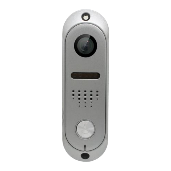
1. Name and Functions of Each Part 1.1. Front and Rear Part Part Name Camera LED for night vision Speaker Call button Microphone Metal bracket for surface mounted Metal bracket for wall corner mounted MIC volume adjust Speaker volume adjust Wires for monitor Wires for electronic lock... -
Page 4: Features
2. Features Pinhole color camera 4 Wires in polarity Water-proof and dust-proof Door lock release Microphone and speaker volume adjustable LED for night vision Surface mount IP65 Protection 120 Degree viewpoint 3. -
Page 5: Connection Diagram
4. Connection Diagram 4.1. Wiring Diagram Please be careful to wiring on polarity. 4.2. Electric Lock Connection Door Lock Controlled with Dry Contact Note: 1. The external power supply must be used according to the lock. 2. The inside relay contact is restricted to AC or DC 3A. 3. -
Page 6: Installation
5. Installation 5.1. Installation location Camera installation location Standard installation height of outdoor station: lens’s height is about 1,400mm above the floor; in this case, camera stack center is about 1,390mm above ground level. Caution of Camera Installation Avoid installing camera exposed to direct ray of light (and sun). -
Page 7: Wiring And Installation
5.2. Wiring and Installation There are two ways to install the doorbells: Surface mounted ◆ Surface mounted(at wall ◆ corner) 6. Specifications Wiring 4 Wire Monitor / 2 Wire Electronic lock Lighting LED for night vision Operation temperature -40 ~ 55 º C With bracket 420g Weight (g)
Need help?
Do you have a question about the LIP-01 and is the answer not in the manual?
Questions and answers