
Subscribe to Our Youtube Channel
Related Manuals for Multitek VIP70


Summary of Contents for Multitek VIP70
- Page 1 MULTITEK IP INTERCOM ROOM MONITOR INSTALLATION AND SHORT USER MANUAL (VIP70, VIP71, VIP72, VIP74, VIP100, VIP101, VIP100 DELUX, VIP102) It obeys the rules of AEEE regulations.
-
Page 2: Table Of Contents
TABLE OF CONTENTS 1. PRODUCT DESCRIPTION ......................4 2. BRIEF FEATURES........................4 3. PACKAGE CONTENTS ......................4 4. SAFETY INSTRUCTIONS ......................4 5. INSTALLLATION ........................4 6. TROUBLE SHOOTING ......................5 7. IP MONITOR SHORT USER MANUAL ..................6 Allocating Ip Number To Room Monitors 7.1. - Page 3 IP INTERCOM SHORT USER MANUAL Thank you for choosing Multitek ip intercom room monitor. This user manual was prepared for using the device more efficiently. MULTITEK IP INTERCOM ROOM MONITOR WARRANTY FOR 2 YEARS AGAINST MANUFACTURING DEFECTS. Multitelk has rights to change the features of the device given in this document prior given any information.
-
Page 4: Product Description
1. PRODUCT DESCRIPTION MULTITEK IP MONITOR is a color video door phone set; used to monitor, call, intercom and open the door locks. This product set can be used in villas, single houses, apartments, hotels, offices etc. giving the user benefits of security and convenience. -
Page 5: Trouble Shooting
6. TROUBLE SHOOTING Problem Solutions No Picture / Signal Make sure all the connections are secure and properly connected. Make sure your monitor is plugged into the PoE switch. Make sure there is nothing obstructing the view of the camera of the door panel. -
Page 6: Ip Monitor Short User Manual
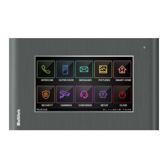
Before powering up the system, please make sure that cabling is correct. Gold-pleated RJ-45 plugs should be used for best quality. When power is given to the device, the screen turns on and Multitek intercom application runs in three minutes. Main screen is shown below:... -
Page 7: Allocating Ip Number To Room Monitors
7.1. Allocating Ip Number To Room Monitors NOTICE: DEVICE SHOULD BE PROGRAMMED BY THE INSTALLATION TECHNICIAN. TO ASSING A ROOM NUMBER TO A DEVICE, YOU HAVE TO KNOW THE BLOCK AND ROOM NUMBER OF THE ROOM. NO ADDITIONAL INFORMATION IS NEEDED. To assign a block and room number to a device, follow the menu pages below: MAIN MENU/ SETUP/ System Settings / Device Number (default keyword to enter systems settings is “0000”) - Page 8 Figure 4: Device Number Settings When you touch Device Number, you will see the current catalogue number of the device. However, you will not be able to edit these fields without entering editing mode. There are two ways to enter editing mode according to type of your device: ...
-
Page 9: Smart Home Relay Application
When the new display page appears (you’ll see Android icon on the bottom left), it is possible to edit the following fields: Enter Block Enter two-digit block number Number i.e. 01 for Block one or a single block apartment Enter Room Enter three-digit room number Number i.e. - Page 10 The setting page that opens after the password is entered is as follows: Click on the channels on the page to select which relay is selected.
- Page 11 7.2.2. Settings Menu To access other relay settings, press the icon on the top right. Figure 7:Settings Menu 7.2.2.1 Alarm Settings The alarm settings option is selected to add alarms to the relays. Figure 8:Alarm Settings Select the desired relay to add alarm. The alarm can only be added to the dual relays. If the relay you select is a single relay, the following warning screen appears.
- Page 12 When you select dual relay, alarm options are opened as below. Alarms are selected and exit the menu. 7.2.2.2 Favorite Settings Relay channels to be added to the scenario are added to favorites. Figure 9:Favorite Settings The default value for devices added to Favorites is 1. This value is changed to 0 by pressing the relay icon which you want.
- Page 13 7.2.2.3 Relay Name To change the names of the relay channels or to give the name of the relay , enter the relay names tab. Write the name and left the menu. CHANGE ICON CHANGE ICON CHANGE ICON...
- Page 14 7.2.2.4 Change Icon Enter icon change menu to select appropriate icon to channels functions. You can exit the menu by selecting the appropriate icons for the channels. 7.2.2.5 Setting Time In the time adjustment category, enter the duration to remain open for the selected channel. 7.2.2.6 Smart Home Relay System Back to the main menu after the settings have been done.
-
Page 15: Smart Home Rf Application
7.3 Smart Home Rf Application First of all, the “Smart Home” tab is entered from the settıngs menu. It is saved by selecting RF this page. Click ”SMART HOME" in the main menU (Figure 7.24) to open the application. Figure 10:Apartment Monitor Main Menu Figure 11:Rooms Screen When you open applicaton, rooms screen appears. - Page 16 The room settings screen has the following keys. (Figure 12) ADD ROOM EDIT ROOM Figure 12:Room Settings Screen DELETE ROOM You can add, edit or delete room with this keys. Press for adding room. “ADD ROOM” screen (Figure 12) appears. You can change room name by click the box on top right.
-
Page 17: Setting Time
Below are the keys on bottom the "ROOM DEVICES" section: PAIRING ADD TO SCENARIO (FAVORITE) CHANGE ICON Figure 13:Add Room Devices SETTING TIME DELETE DEVICE To make the pairing of the devices added to the room devices section, first press the programming key of the device and then press the button located under the room devices section. - Page 18 Figure 14:Edit Room Screen Change Icon Enter icon change menü (Figure 7.28) to select appropriate icon to devices functions. First of all select the device , and then press the button located under the room devices section. Icons appears, selecting the appropriate icons for the devices.
- Page 19 Setting Time To set the time, press the hourglass button under the Room Devices section. The duration of the devices is entered and saved. Figure 16: Setting Time Favorite Settings The devices to be added to the scenario are added to favorites from the star icon under the Room devices section.
-
Page 20: Smart Home Knx System
7.3.4 Smart Home Rf System Back to the main menu after the settings have been done. When you enter the smart home page from the main menu, the screen will be as follows: 7.4 Smart Home Knx System Enter smart home application simply by tapping “SMART HOME” icon on the home screen. If the smart home feature is not supported by your monitor, “NOT SUPPORTED”... -
Page 21: Adding Rooms And Devices
Figure 17:Home screen When you open the menu, you see the list of your rooms and scenario icon (Figure 6). When you click scenario icon, you can see the list of your scenarios. When there is no setup at the very beginning, you will just see the scenario icon. Figure 18:Main KNX screen To setup smart home functionalities, press “settings”... - Page 22 Figure 19:Room Settings In order to add a room press “+” button. “Add Room” (Figure 8) screen will show up. Name the room by typing your rooms name to “Name” section located at the top right. Different type of devices are defined in “Device Types” list. These are Curtain, Dimmer, Lights, Air conditioner, Socket, On/off and Heat Control devices.
- Page 23 Note: To save changes in Add Room / Edit Room menus’, exit by pressing okay (check) icon on the right. If you press returning back icon on the top left corner, your settings will not be saved. Figure 21:Curtain Configuration Screen Figure 22:Dimmer Configuration Screen Figure 23:Socket configuration screen...
- Page 24 Figure 24:Lights Configuration Screen Figure 25:On/off Configuration Screen Figure 26:Air Conditioner Configuration Screen...
- Page 25 7.5.1. Editing Rooms And Devices In order to edit an existing room, select the room and press to editing icon (pencil icon) on the main Smart Home Settings menu. A screen similar to add room screen will show up. Same steps that are used while adding a room will be used. In the figures below there are examples of room editing screens.
- Page 26 7.5.2. Adding Scenarios Scenarios are present on the main page of Smart Home menu (figure 18). There are 2 kinds of scenarios: 1- KNX Scenario 2- Special Scenarios 7.5.3. KNX Scenarios In home and Out of Home are default scenarios that are present for all devices. Figure 30:Scenarios Figure 31:Default scenarios: In Home, Out of Home In order to add a scenario, go to Smart Home Settings located on the top right corner of the screen.
- Page 27 Figure 32:Scenario Settings Figure 33:Adding a new scenario 7.5.4. Special Scenerios There are 3 kinds of special scenarios. Triggered Scenario Timed Scenario Scenario that can be assigned date To add custom scenarios, go to the smart home settings page. Enter scenario settings and press add scenarios.
- Page 28 Select the custom scenario option from the page that opens. After selecting the custom scenario, the following screen will appear. Alarm, Time, Device can be added from the options on the left by entering the scenario name. Triggered Scenarios Alarm scenarios. When the zone is activated, the scenario is automatically activated and executed according to the function assigned to the devices.
- Page 29 right. By pressing the icon, the date is assigned. The scenario is recorded by selecting which days and at what time it is desired to be active. 7.5.5. Editing Scenarios In scenario setting screen, choose the scenario that you want to edit and tap editing icon (pencil located in the middle) Figure 34:Editing Scenario 7.5.6.
- Page 30 Figure 36:Deleting Scenario 7.5.7. Room Based Device Control Screen In the main Smart Home menu, select a room to see the devices that you have added. To change device names, tap settings icon located at the top right corner of the screen and “Change device names”...
- Page 31 Figure 37: Devices in a Room Named "Kitchen" with Turn on/off lights and Blinds Different devices have different icons and functionalities. • Blinds / curtains can move up or down and can be stopped (Figure 36) • Control of light intensity by dimmer device (Figure 37) •...
- Page 32 Figure 39:Turn on / off Lights Control Figure 40:Socket / Plug Control Figure 41:On / off Control 7.5.8. Editing Alarm Go Smart Home settings from the main Smart Home screen by clicking to settings icon on the top right corner. Press the orange security icon (see figure below).
- Page 33 Figure 422: Alarm settings For example; Actuator 1.3.1 we want to make this lamp connected to a coded lamp. In case this lamp is connected to the winding; the lamp will remain on for as long as the alarm is set, and the lamp will go off if an alarm occurs.
-
Page 34: Ip Door Panel Short User Manual
8. IP DOOR PANEL SHORT USER MANUAL DIP40 door panel has four touch buttons on the sides of the LCD. Touch these buttons to navigate. 8.1. Allocating Ip Number To Ip Door Panels (For Dip40) NOTICE: DEVICE SHOULD BE PROGRAMMED BY THE INSTALLATION TECHNICIAN. TO ASSING A DOOR NUMBER TO A DEVICE, YOU HAVE TO KNOW THE BLOCK AND NUMBER OF DOORS IN THE BLOCK. -
Page 35: Calling The Rooms From The Door Panel
- “TO SAVE, TOUCH SAVE BUTTON” message appears. To save the records , touch the left upper button of the device. (Figure 13) Figure 46:Enter Door Number Figure 47:Saving IP Number 8.2. Calling The Rooms From The Door Panel All door panels can call rooms in its own block. Type the room number on the panel and touch “CALL” button. Dialed room number can be 1,2 or 3 digits according to the size / numbering logic of the block. -
Page 36: Calling The Guard And The Doorkeeper From The Panel
Figure 48:Main Outdoor Screen Figure 49:Calling Room Figure 50:Conversation Screen 8.3. Calling The Guard And The Doorkeeper From The Panel The door panel has four touch buttons on the sides of the LCD. Touch the buttons to call the guard or the doorkeeper. -
Page 37: Phone Book Feature Of The Door Panel
Figure 51:Main Menu 8.4. Phone Book Feature Of The Door Panel The phone book is a list of room numbers and their names entered by the phone book program. It is used to search the names of the people living in the apartment and call the rooms by touching a single button. To start using the phone book feature, please touch “GUIDE”... -
Page 38: Open The Door By Entering Password
8.5. Open The Door By Entering Password The user touches the right lower bottom button “PASSWORD” on the door panel, enters his own “four-digit door opening password”. If the password entered is correct the door opens, otherwise not. The related information is given on the screen.
Need help?
Do you have a question about the VIP70 and is the answer not in the manual?
Questions and answers