Table of Contents
Advertisement
Quick Links
Advertisement
Table of Contents

Related Manuals for Energizer EZG2200iUK


Summary of Contents for Energizer EZG2200iUK
- Page 1 SERIE EZG EZG2200i/EZG2200iUK USER GUIDE...
- Page 2 Energizer and certain graphic designs are trademarks of Energizer Brands, LLC and related subsidiaries and are used under license by Builder SAS. All other brand names are trademarks of their respective owners. Neither Builder SAS nor Energizer Brands, LLC is affiliated with the respective owners of their trademarks.
- Page 3 Thanks for choosing the EZG Series! You're excited to power up, so we'll keep this brief. Let's get started! - 3 -...
-
Page 4: Table Of Contents
CONTENT 1. SAFETY INFORMATION ................- 9 - 1.1 OPERATOR ATTENTION ............... - 9 - 1.2 EXHAUST FUMES HAZARDS ............. - 10 - 1.3 ELECTRIC SHOCK HAZARDS ............ - 11 - 1.4 FIRE AND BURN HAZARDS ............- 12 - 1.5 CONNECTION NOTES .............. - Page 5 9. SPECIAL REQUIREMENTS ..............- 48 - 10. MAINTENANCE ..................- 49 - 10.1 ENGINE OIL CHANGE ............... - 51 - 10.2 AIR CLEANER SERVICE ............- 53 - 10.3 SPARK PLUG SERVICE ............. - 54 - 10.4 SPARK ARRESTER MAINTENANCE......... - 56 - 10.5 CLEANING FUEL TANK FILTER ..........
- Page 6 Read this manual carefully before operating this generator. This manual should stay with this generator if it is sold. The engine exhaust fumes from this product contain poisonous carbon monoxide(CO) to cause loss of consciousness and may lead to death. - 6 -...
- Page 7 Exhaust contains poisonous carbon monoxide (CO) gas that can build up to dangerous levels in closed areas. Breathing CO can cause unconsciousness or death. Never run the generator in a closed or even partially closed area where people may be present. The generator is a potential source of electrical shock if misused.
- Page 8 INTRODUCTION Congratulations on your selection of a marvelous generator. This manual will provide you with a good basic understanding of the operation and maintenance of this machine, please read it carefully. These signal words mean: You WILL be KILLED or SERIOUSLY HURT if you don’t follow instructions.
-
Page 9: Safety Information
1. SAFETY INFORMATION 1.1 OPERATOR ATTENTION ⚫ Read and understand this manual before operating the generator. Place the generator in a place where pedestrians, children and ⚫ pets are not likely to touch. Never let children operate the generator. ⚫ The generator is allowed to be put down, but ONLY lay on the Drawbar Side, and only after stopping the... -
Page 10: Exhaust Fumes Hazards
parts may be damaged because of bad cooling. 1.2 EXHAUST FUMES HAZARDS ⚫ Exhaust fumes contains poisonous carbon monoxide(CO), a colorless and odorless gas. Breathing CO can cause loss of consciousness and may lead to death. ⚫ Never run your generator inside a garage or house, even if door or window is open. -
Page 11: Electric Shock Hazards
1.3 ELECTRIC SHOCK HAZARDS ⚫ Never operate the engine in rain, snow or wet locations. ⚫ Never touch the machine with wet hands. ⚫ Ground unit to avoid electrical hazards. - 11 -... -
Page 12: Fire And Burn Hazards
1.4 FIRE AND BURN HAZARDS Gasoline is extremely flammable and explosive under certain ⚫ conditions. Do not smoke or allow flames or sparks where the generator is refueled or where gasoline is stored. Refuel in a well-ventilated area with the engine stopped and cooled. ⚫... -
Page 13: Connection Notes
⚫ Keep the generator at least 1 m (3 ft.) from buildings or other equipment, or the generator may overheat. ⚫ Let the engine cool before storing the generator indoors. 1.5 CONNECTION NOTES Do not connect to a building electrical system unless an ⚫... -
Page 14: Important Label Locations
2. IMPORTANT LABEL LOCATIONS Please read the following labels carefully before operating this generator. ① ② - 14 -... - Page 15 ③ ④ ⑤ ⑥ - 15 -...
- Page 16 Danger! Electrical hazard Guarantee sound power level Read instruction manual before use Risk of being burnt Caution! Caution! Fire hazard Carbon monoxide (CO) danger Caution - 16 -...
- Page 17 • The operator must know the principles of functioning and the structure of the generator and the motor. He must know how to stop the motor in case of urgency and how to manipulate the controls. • Never let children use this device. •...
- Page 18 • Do not transport or move the generator until it has cooled down. • Perform periodic maintenance and resolve problems that appear immediately. Do not run the generator before correcting any fault detected. • The generator uses a system of air-cooling, and it is necessary to clean its components regularly, including the grilles, the cover of the fan and the fan itself so as to ensure cooling.
- Page 19 electric shock. If it needs to be replaced with another cut-out, the latter must correspond to the technical specifications of the generator. Due to important mechanical constraints, it is necessary to use a flexible sheathed cable with a strong rubber protective layer (conforming to IEC 245-4) or a similar cable.
- Page 20 • Due to high mechanical stresses, only tough rubber-sheathed flexible cable (in accordance with IEC 60245-4) or the equivalent should be used. • The user shall conform to regulations of electrical safety applicable to the place where the generating sets are used. •...
- Page 21 • Never fill the fuel tank while smoking or near a naked flame. • Make sure you don’t spill fuel on the motor and the exhaust grille of the generator during filling with fuel. • Keep the fuel in an appropriate recipient and sheltered from any sources of fire. •...
- Page 22 • Do not run the generator under rain or snow. • Do not run the generator near water. • Connect the generator to earth. Use a sufficiently thick conductor for the earth wire. • Do not operate the generator in parallel with another generator. •...
- Page 23 device connected is not designed to function with a voltage tolerance of +/- 10% or a frequency tolerance of +/- 3 % compared with those of the generator. Protection of the environment • You must periodically check the silencer (Before doing this, switch off the generator and let it cool completely).
-
Page 24: Unit Description
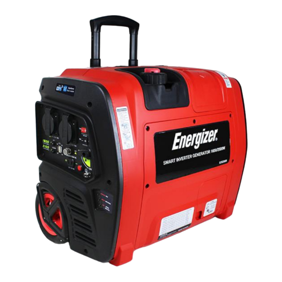
3. UNIT DESCRIPTION 3.1 COMPONENTS IDENTIFICATION (1). Control Panel: Location of generator controls and output receptacles. - 24 -... - Page 25 (2). Fuel Cap: Access to fuel tank for filling. (3). Fuel Cap Vent Lever: Control valve between atmosphere and fuel tank. (4). Carrying Handle: Lift the generator by this handle only. (5). Starter Grip: Pull starter grip for starting engine. (6).
-
Page 26: Control Panel
3.2 CONTROL PANEL (1). Fuel Tap: Controls fuel supply to the carburetor. (2). AC Receptacles: AC Output receptacles for connecting AC devices. (3). 12V DC Receptacle: Connection for re-charging 12V DC automotive-style batteries while generator is in operation. (4). 12V DC Circuit Breaker: Overload protection for the 12VDC charging system. -
Page 27: Preparation
(9). ECO Switch: Turning on this switch can slow the engine speed when the load is reduced to save fuel, lessen noise and engine wear. (10). Reset Button: This switch can be used to recover output of the generator under the condition of overload protection, and unnecessary to restart engine overall. - Page 28 Loosen Add Engine Oil: (1). Open the Oil Maintenance Cover 1, and remove the Oil Cap 2. (2). Fill the specified amount of the recommended engine oil, and then install and tighten the Oil Cap. NOTE Make certain the generator is on a flat, level surface. ⚫...
-
Page 29: Fuel
4.2 FUEL ⚫ Gasoline is extremely flammable and explosive under certain conditions. Do not smoke or allow flames or sparks where the generator is refueled or where gasoline is stored. ⚫ Refuel in a well-ventilated area with the engine stopped. ⚫... -
Page 30: Starting The Engine
⚫ You may use regular unleaded gasoline containing no more than 10% Ethanol (E10). ⚫ Make certain the generator is on a flat, level surface. ⚫ Fuel tank capacity: 4.2L. 5. STARTING THE ENGINE - 30 -... -
Page 31: Check Engine Oil
5.1 CHECK ENGINE OIL Check the oil BEFORE EACH USE with the generator on a level surface and the engine stopped. RECOMMENDED OIL: 4-stroke engine oil, SAE 10W-40, API SE/SF/SG/SH/SJ or higher. Loosen (1). Open the Oil Maintenance Cover 1. (2). -
Page 32: Check Fuel
⚫ When the engine shuts down automatically by the low oil protection, the LOW OIL LEVEL LED (yellow) will come on, and unless you refill with oil, the engine will not start again. 5.2 CHECK FUEL ⚫ Do not smoke or allow flames or sparks where the generator is refueled or where gasoline is stored. -
Page 33: Open The Fuel Cap Vent Lever
NOTE ⚫ Use only unleaded gasoline. ⚫ Never use an oil/gasoline mixture. ⚫ Fuel tank capacity: 4.2L. ⚫ Make certain the generator is on a flat, level surface when check the fuel. 5.3 OPEN THE FUEL CAP VENT LEVER Turn the Fuel Cap Vent Lever 1 to “ON” position. "ON"... -
Page 34: Open The Fuel Tap
5.4 OPEN THE FUEL TAP Turn the Fuel Tap 1 to “ON” position. "ON" position "OFF" position - 34 -... -
Page 35: The Engine Switch & Eco Switch
5.5 THE ENGINE SWITCH & ECO SWITCH (1). Turn the Engine Switch (Red) 1 to “ON” position. (2). Turn the ECO Switch (Black) 2 to “OFF” position. "ON" position "OFF" position - 35 -... -
Page 36: Use Choke
5.6 USE CHOKE Pull the Choke Knob 1 fully out to "START" position. "RUN" position "START" position NOTE ⚫ The Choke is not required to start a warm engine. Push the Choke Knob into the "RUN" position. ⚫ Keep the Choke Knob in "START" position for only 2 pulls of the recoil starter. -
Page 37: Start The Engine
5.7 START THE ENGINE ⚫ Exhaust fumes contains poisonous carbon monoxide(CO), a colorless and odorless gas. Breathing CO can cause loss of consciousness and may lead to death. ⚫ Operate the generator in a well-ventilated area. Never run your generator inside a garage or house, even if door or window is open. -
Page 38: Close Choke
⚫ Normally the engine can be started within three pulls. Keep the Choke Knob in "START" position for only 2 pulls. After second pull, push the Choke Knob into the “RUN” position for up to the next 3 pulls. 5.8 CLOSE CHOKE After starting the engine, push the Choke Knob 1 fully into the “RUN”... -
Page 39: Ac Operation
NOTE Wait a few seconds until the engine speed is stable before closing the choke, and more time waiting if weather is cold. 6. AC OPERATION 6.1 USE THE GENERATOR: After starting the engine, let it run for 2 or 3 minutes to warm up, then you can use the generator as follows: (1). - Page 40 "OFF" position "ON" position Be sure any electric devices are turned off before plugging them in. NOTE ⚫ The ECO Switch 1 must be turned to “OFF” position when using electric devices that require a large starting current, such as a heavy compressor or some high electrical loads. ⚫...
-
Page 41: Shut Down The Generator
appliance or wire. ⚫ When an electric motor is started, the OVERLOAD LED (red) 5 may come on. This is normal if the OVERLOAD LED (red) 5 goes off after a few seconds. 6.2 SHUT DOWN THE GENERATOR: Once the generator is no longer needed it can be shut down: (1). - Page 42 (3). Turn the Engine Switch 3 to “OFF” position. (4). and then turn the Fuel Cap Vent Allow the engine to cool well, Lever 4 to “OFF” position. "ON" position "OFF" position "OFF" position "ON" position "ON" position "OFF" position - 42 -...
-
Page 43: Dc Operation
NOTE ⚫ TURN OFF all electrical loads connected to the generator AC Receptacles 1 before shutting down by Gen-mate APP in smartphones. ⚫ If shutting down by Gen-mate APP in smartphones, the above step 2/3 is unnecessary, and step 4 should be done before moving or storing the generator. -
Page 44: Connecting The Battery Charging Cable
7.1 CONNECTING THE BATTERY CHARGING CABLE: (1). before connecting the Battery Charging Cable 1 to a battery that is installed in a vehicle, disconnect the vehicle battery ground cable from the negative (-) battery terminal. (2). Plug the Battery Charging Cable 1 into the 12V DC Receptacle 2 of the generator. -
Page 45: Disconnecting The Battery Charging Cable
⚫ NEVER reverse the polarity when connecting the battery terminals to the charging jack. Severe damage may occur to the generator and battery. ⚫ Do not start the vehicle while the battery charging cable is connected and the generator is running. The vehicle or the generator may be damaged. -
Page 46: Ac Parallel Operation
8. AC PARALLEL OPERATION Two EZG2000i generators can be operated in parallel to increase the total available output power reach 3.6 kW. A Parallel Kit 2(optional equipment) is required for the parallel operation. 8.1 START AC PARALLEL (1). Disconnect or turn off all electrical loads from both generators. (2). -
Page 47: Stop Ac Parallel
removed. ⚫ If an appliance begins to operate abnormally, becomes sluggish or stops suddenly, turn it off immediately. Then disconnect the appliance from receptacles of the Parallel Kit 2, and determine whether the problem is the appliance, or if the rated load capacity of the generator has been exceeded. -
Page 48: Special Requirements
NOTE TURN OFF all electrical loads connected to receptacles of the Parallel Kit 2 before shutting down by Gen-mate APP in smartphones. 9. SPECIAL REQUIREMENTS NOTE ⚫ DO NOT modify the generator in any way. ⚫ The generator is allowed to be put down, but ONLY lay on the Drawbar Side 1. -
Page 49: Maintenance
(3). Close the Fuel Cap tightly. (4). Turn OFF the Fuel Cap Vent Lever. ⚫ DO NOT turn the Fuel Cap Vent Lever to “OFF” position before cooling the engine. Allow the engine to cool well, if not, the fuel tank can be crushed by cold contraction of the fuel gas in the fuel tank. - Page 50 ⚫ Use ours or equivalent quality parts for replacement. Ask an authorized dealer for further attention. ⚫ Maintenance Schedule Regular Service Period (5) Every 6 Every 1 Every 2 Each months year or years or Item or 50 100 hrs. 300 hrs.
-
Page 51: Engine Oil Change
schedule could result in non-warrantable failures. 10.1 ENGINE OIL CHANGE Loosen - 51 -... - Page 52 Ø30mm UPPER LIMIT LOWER LIMIT Drain the used oil while the engine is warm. Warm oil drains quickly and completely. (1). Turn OFF the Fuel Tap, Close the Fuel Cap tightly and turn OFF the Fuel Cap Vent Lever to reduce the possibility of fuel leakage. (2).
-
Page 53: Air Cleaner Service
NOTE ⚫ Do not tilt the generator when adding engine oil. This could result in overfilling and damage to the engine. ⚫ Improper disposal of engine oil can be harmful to the environment. The used oil should be put in a sealed container, and take it to a recycling station. -
Page 54: Spark Plug Service
(1). Loosen five screws and remove the Maintenance Cover 1. (2). Loosen the Cover Screw 2 and remove the Air Filter Cover 3. (3). Wash the Sponge 4 in a solution of household detergent and warm water, then rinse thoroughly, or wash in nonflammable or high flash point solvent. - Page 55 Loosen (1). Unscrew the screw 5, and then remove the Spark Plug Maintenance Cover 1. (2). Remove the Spark Plug Cap 2. (3). Use a Spark Plug Wrench 4 to remove the Spark Plug 3. (4). Inspect the Spark Plug 3. Replace it if the electrodes are worn or if the insulator is cracked, chipped, or fouled.
-
Page 56: Spark Arrester Maintenance
(6). Check that the spark plug sealing washer is in good condition. (7). After the Spark Plug 3 is seated; tighten with a Spark Plug Wrench to compress the washer. If installing a new spark plug, tighten 1/2 turn after the spark plug seats to compress the washer. If reinstalling a used spark plug, tighten 1/8-1/4 turn after the spark plug seats to compress the washer. - Page 57 ⚫ The Spark Arrester must be serviced every 100 hours to maintain its efficiency. Five Screws - 57 -...
- Page 58 Screen A Screen B Clean the Spark Arrester 1 as follows: (1). Remove the five screws, and remove the Back Cover 2. (2). Remove the Spark Arrester 1. (3). Use a brush to remove carbon deposits from the Screen A and B. (4).
-
Page 59: Cleaning Fuel Tank Filter
10.5 CLEANING FUEL TANK FILTER Never use the gasoline while smoking or in the vicinity of an open flame. (1). Remove the Fuel Cap 1 and Fuel Tank Filter 2. (2). Clean the Fuel Tank Filter 2 with gasoline. If damaged, replace it. (3). -
Page 60: Transportation And Storage
11. TRANSPORTATION AND STORAGE Transport or store the generator only if it has cooled ⚫ completely. ⚫ Before transporting and storing the generator, proceed as follows: (1). Turn OFF the Fuel Tap. (2). Allow the generator to cool off before moving or storing. (3). -
Page 61: Drain The Fuel From The Carburetor
11.1 DRAIN THE FUEL FROM THE CARBURETOR "ON" position "OFF" position Five screws Loosen - 61 -... -
Page 62: Drain The Fuel From Fuel Tank
(1). Turn the Fuel Tap 5 to the “OFF” position. (2). Loosen five screws and remove the Maintenance Cover 4. (3). Take out the Drain Hose 1 from the hole at the bottom casing, and put it into a suitable container. (4). -
Page 63: Drain The Fuel From The Carburetor Again
11.3 DRAIN THE FUEL FROM THE CARBURETOR AGAIN Tighten (1). Turn the Fuel Cap Vent Lever to “ON” position. (2).Turn the Fuel Tap to the “ON” position. (3). Put the Drain Hose 1 into a suitable container. (4). Loosen the Drain Screw 3 counterclockwise. (5). -
Page 64: Engine
11.4 ENGINE (1). While engine is still warm, drain oil from crankcase. Refill with the recommended new oil. (2). Remove spark plug and pour about 15ml (1/2 ounce) of engine oil into the cylinder through spark plug hole on the engine cylinder head, and cover spark plug hole with rag. -
Page 65: Trouble Shooting
12. TROUBLE SHOOTING When the engine cannot be started: Is there fuel in the tank? Refill the fuel tank Are the engine switch and fuel Turn the two switches on tap ON? Is the fuel cap vent lever ON? Turn the fuel cap vent lever on Does the choke knob pull out? Pull choke knob... - Page 66 Engine starts, and then shuts down: Is the fuel level low? Add fuel to tank Is fuel cap vent lever closed? Open fuel cap vent lever Is engine oil level incorrect? Check engine oil level, add or drain as needed Is the fuel in the fuel tank Replace fuel in the fuel tank, contaminated?
- Page 67 Engine starts, then runs rough: Is the choke stuck or left on? Turn choke to run position Is the air cleaner dirty or Clean or replace the air filter clogged? element Is the spark plug defective or Replace or clean spark plug dirty? Contact with an authorized dealer...
- Page 68 No AC output: Is the generator overloaded? Reduce loads and push reset button to reset module Is AC voltage low? Verify the choke is on run position, and check fuel in the fuel tank and carburetor, and check air filter Is the electrical device short Verify condition...
- Page 69 No DC output Is the DC voltage low? Verify ECO Switch is on the "0" OFF position Is the DC circuit protector Push the DC circuit protector OFF? Check the electrical appliance Change replace for any fault appliance Contact with an authorized dealer - 69 -...
-
Page 70: Specifications
Fuel leaks from drain hoses. Is the pressure in fuel tank too Open fuel tank vent to balance high? pressure Is the carburetor drain in bowl Turn drain screw clockwise to not closed? close Contact with an authorized dealer 13. SPECIFICATIONS DIMENSIONS AND WEIGHT Overall Length 530mm (20.9 in) - Page 71 Fuel Unleaded gasoline Fuel Tank Capacity 4.2L (1.11 US gal) Engine Oil Capacity 0.4L (0.42 US qt) Ignition System Type E6RTC (TORCH) Spark Plug 0.7~0.8mm (0.027~0.031in) Measured LpA: 70,46dB(A), K=3,0dB(A) LwA: 91,46 dB, K = 0,75 dB(A) Noise Level Guarantee sound power level LwA: 92 dB(A) GENERATOR Rated Voltage...
-
Page 72: Wiring Diagram
14. WIRING DIAGRAM - 72 -... -
Page 73: Environment Correction
15. ENVIRONMENT CORRECTION The rated power output is based on the standard condition as follows: Altitude:0m ⚫ ⚫ Ambient temperature: 25℃ ⚫ Relative humidity: 30% Factor of environment correction C: Ambient temperature℃ Altitude(m) 0.98 0.96 0.93 0.90 0.93 0.91 0.89 0.87 0.84 1000... - Page 74 The manufacturer warrants the product against defects in materials and workmanship for a period of 2 years from the date of purchase to the original purchaser. The guarantee applies when the product is used as a home tool. The warranty does not extend for failures due to normal wear and tear.
- Page 75 As a result, the product may differ from the information contained herein, but any alteration will only be implemented without prior notice if it is classified as an improvement of the previous specification. READ THE MANUAL CAREFULLY BEFORE USING THE MACHINE. When ordering spare parts, please quote the part number or code, this can be found in the parts list included in this manual.
- Page 76 CE DECLARATION BUILDER SAS ZI, 32 RUE ARISTIDE BERGES – 312070 CUGNAUX – FRANCE Declares that the machinery designated below: Inverter Generating set Model: EZG2000i Serial number: Complies with the provisions of the Directive “machinery” 2006/42/EC and national laws transposing it: Also complies with the following European directives: EMC Directive 2014/30/EU ROHS Directive 2011/65/EU...
Need help?
Do you have a question about the EZG2200iUK and is the answer not in the manual?
Questions and answers