Table of Contents
Advertisement
Quick Links
Advertisement
Table of Contents

Related Manuals for Energizer EZG2001i


Summary of Contents for Energizer EZG2001i
- Page 1 ORIGINAL INSTRUCTIONS...
- Page 2 ©2019 Energizer. Energizer and certain graphic designs are trademarks of Energizer Brands, LLC and related subsidiaries and are used under license by Builder SAS. All other brand names are trademarks of their respective owners. Neither Builder SAS nor Energizer Brands, LLC is affiliated with the respective owners of their...
- Page 3 ORIGINAL INSTRUCTIONS Thanks for choosing the EZG Series! You're excited to power up, so we'll keep this brief. Let's get started! - 3 -...
-
Page 4: Table Of Contents
ORIGINAL INSTRUCTIONS CONTENT 1. SAFETY INFORMATION ................- 9 - 1.1 OPERATOR ATTENTION ............. - 10 - 1.2 EXHAUST FUMES HAZARDS ............. - 22 - 1.3 ELECTRIC SHOCK HAZARDS ....Erreur ! Signet non défini. 1.4 FIRE AND BURN HAZARDS ............- 23 - 1.5 CONNECTION NOTES .............. - Page 5 ORIGINAL INSTRUCTIONS 5.5 THE ENGINE SWITCH & ECO SWITCH........- 44 - 5.6 USE CHOKE ................. - 45 - 5.7 START THE ENGINE ..............- 47 - 5.8 CLOSE CHOKE ................- 51 - 6. AC OPERATION..................- 52 - 6.1 USE THE GENERATOR: ..............
- Page 6 ORIGINAL INSTRUCTIONS 10.3 DRAIN THE FUEL FROM THE CARBURETOR AGAIN ..... - 79 - 10.4 ENGINE ..................- 80 - 11. TROUBLE SHOOTING ................. - 80 - 12. SPECIFICATIONS................. - 87 - 13. WIRING DIAGRAM ................- 90 - 14. ENVIRONMENT CORRECTION ............- 91 - - 6 -...
- Page 7 ORIGINAL INSTRUCTIONS Leggere attentamente il presente manuale prima di utilizzare il presente generatore. Il presente manuale deve accompagnare il generatore in caso di vendita. I fumi di scarico del motore di questo prodotto contengono monossido di carbonio velenoso. (CO) che causa la perdita di coscienza e può...
- Page 8 ORIGINAL INSTRUCTIONS Tenere a portata di mano il presente manuale, in modo da poterlo consultare in qualsiasi momento. Ci riserviamo il diritto di modificare questo prodotto o manuale in qualsiasi momento e senza preavviso. LEGGERE ATTENTAMENTE IL PRESENTE MANUALE PRIMA DI UTILIZZARE IL GENERATORE.
- Page 9 ORIGINAL INSTRUCTIONS Queste parole chiave significano: Se non si seguono le istruzioni, si verrà UCCISI o si resterà GRAVEMENTE FERITI. Se non si seguono le istruzioni, si può essere UCCISI o restare GRAVEMENTE FERITI. Se non si seguono le istruzioni, si può restare gravemente feriti.
- Page 10 ORIGINAL INSTRUCTIONS 1. INFORMAZIONI SULLA SICUREZZA 1.1 ATTENZIONE DELL'OPERATORE 1. ISTRUZIONI DI SICUREZZA Avviso: 1. Attenzione! I gas di scarico sono tossici. Non azionare il generatore in un locale senza impianto di ventilazione! 2. I bambini devono essere protetti mantenendoli a una distanza di sicurezza dal gruppo elettrogeno! 3.
- Page 11 ORIGINAL INSTRUCTIONS Istruzioni di sicurezza generali • L'operatore deve conoscere i principi di funzionamento e la struttura del generatore e del motore. Deve sapere come arrestare il motore in caso di emergenza e come manipolare i comandi. • Non lasciare mai che i bambini utilizzino questo dispositivo. •...
- Page 12 ORIGINAL INSTRUCTIONS • Installare il generatore in un luogo ben ventilato e assicurarsi che ci siano almeno 1,5 metri tra il generatore e le pareti dell'edificio o altre apparecchiature. Non collocare liquidi o gas infiammabili vicino al generatore. • Non far funzionare il generatore in ambienti chiusi o scarsamente ventilati.
- Page 13 ORIGINAL INSTRUCTIONS • Controllare periodicamente l'installazione dei collegamenti e la tenuta dei fissaggi, eventualmente serrandoli nuovamente. • Pulire periodicamente i componenti del filtro dell'aria e sostituire il filtro dell'aria quando necessario. • Rimuovere tutte le apparecchiature elettriche collegate prima di avviare o arrestare il generatore.
- Page 14 ORIGINAL INSTRUCTIONS Se si utilizza un cavo di prolunga elettrico, la lunghezza totale del prolungamento non deve superare i 60 m se la sezione del cavo è di 1,5 e non deve superare i 100 m se la sezione del cavo è di 2,5 mm Prescrizioni supplementari per gruppi elettrogeni a bassa potenza destinati a persone non esperte •...
- Page 15 ORIGINAL INSTRUCTIONS • Prima dell'uso controllare che il gruppo elettrogeno e il suo equipaggiamento elettrico (compresi i cavi e i collegamenti a spina) non siano difettosi. • La protezione contro le scosse elettriche dipende dagli interruttori magnetotermici appositamente adattati al gruppo elettrogeno.
- Page 16 ORIGINAL INSTRUCTIONS Misure di sicurezza durante il riempimento del serbatoio del carburante • Il carburante è estremamente infiammabili e velenoso. • Questo generatore utilizza solo benzina; qualsiasi altro tipo di carburante danneggia il motore. • Non riempire eccessivamente il serbatoio di benzina per evitare fuoriuscite.
- Page 17 ORIGINAL INSTRUCTIONS • Conservare il carburante in un recipiente adeguato e al riparo da qualsiasi fonte di incendio. • Eseguire il riempimento in un luogo sicuro e aprire lentamente il tappo del serbatoio per scaricare la pressione accumulatasi all'interno del serbatoio. Eliminare eventuali gocce di benzina versate prima di avviare il motore.
- Page 18 ORIGINAL INSTRUCTIONS riserva agli impianti elettrici esistenti, quest'ultimo deve essere effettuato esclusivamente da un elettricista qualificato, che deve prendere in considerazione le differenze tra le apparecchiature in funzione che utilizzano la rete elettrica pubblica e il generatore. Per evitare scosse elettriche, è necessario seguire le seguenti istruzioni: •...
- Page 19 ORIGINAL INSTRUCTIONS Il collegamento di un generatore utilizzato per l'alimentazione ausiliaria all'impianto elettrico di un edificio deve essere effettuato da un elettricista qualificato e in conformità alle disposizioni delle leggi e norme vigenti in materia di energia elettrica. Collegamenti errati possono causare perdite di corrente dal generatore alle linee del fornitore pubblico di energia elettrica.
- Page 20 ORIGINAL INSTRUCTIONS Si possono verificare danni se il dispositivo collegato non è progettato per funzionare con una tolleranza di tensione di +/- 10% o una tolleranza di frequenza di +/- 3% rispetto a quella del generatore. Protezione dell'ambiente • Controllare periodicamente il silenziatore (prima di procedere spegnere il generatore e lasciarlo raffreddare completamente).
- Page 21 ORIGINAL INSTRUCTIONS ⚫ Collocare il generatore in un luogo in cui le persone presenti, i bambini e gli animali domestici non sono suscettibili di touch. Non lasciare che i bambini utilizzino il generatore senza sorveglianza. ⚫ Il generatore può essere inclinato verso il basso, ma appoggiato SOLO sul lato timone di traino e soltanto dopo aver arrestato il...
-
Page 22: Exhaust Fumes Hazards
ORIGINAL INSTRUCTIONS ⚫ NON rimuovere alcun coperchio del gruppo elettrogeno quando il motore è acceso. In caso contrario, l'inverter, l'alternatore o altre parti elettriche potrebbero subire danni a causa di un raffreddamento insufficiente. 1.2 EXHAUST FUMES HAZARDS PERICOLO ⚫ I fumi di scarico contengono monossido di carbonio(CO), un gas incolore e inodore. - Page 23 ORIGINAL INSTRUCTIONS Non far funzionare mai il generatore all'interno di un garage o ⚫ di una casa, anche se la porta o la finestra sono aperte. Azionare il generatore in un'area ben ventilata. 1.3 PERICOLI DA SCOSSA ELETTRICA AVVERTIMENTO ⚫ Non azionare mai il motore sotto la pioggia, neve o in luoghi bagnati.
- Page 24 ORIGINAL INSTRUCTIONS 1.4 PERICOLI DI INCENDIO E USTIONI SOLO BENZINA SENZA PIOMBO Utilizzare solo dopo l'arresto del motore ⚫ La benzina risulta estremamente infiammabile ed esplosiva in determinate condizioni. Non fumare e non lasciare fiamme o scintille nell'area in cui il generatore viene rifornito o in cui viene conservata la benzina.
- Page 25 ORIGINAL INSTRUCTIONS ⚫ Il generatore può essere inclinato verso il basso, ma appoggiato soltanto sul lato timone di traino. Se appoggiato sull'altro lato, l'OLIO potrebbe fuoriuscire e danneggiare il motore o la vostra proprietà. Anche il CARBURANTE può fuoriuscire e causare un INCENDIO o ESPLOSIONE. ⚫...
- Page 26 ORIGINAL INSTRUCTIONS 1.5 NOTE SUL COLLEGAMENTO ⚫ Non collegare a un impianto elettrico dell'edificio se non è stato installato un interruttore di isolamento da un elettricista qualificato. ⚫ Evitare di collegare il generatore in parallelo con qualsiasi altro generatore. - 26 -...
-
Page 27: Important Label Locations
ORIGINAL INSTRUCTIONS 2. IMPORTANT LABEL LOCATIONS Please read the following labels carefully before operating this generator. - 27 -... - Page 28 ORIGINAL INSTRUCTIONS ① ② ③ ④ - 28 -...
- Page 29 ORIGINAL INSTRUCTIONS ⑤ ⑥ - 29 -...
-
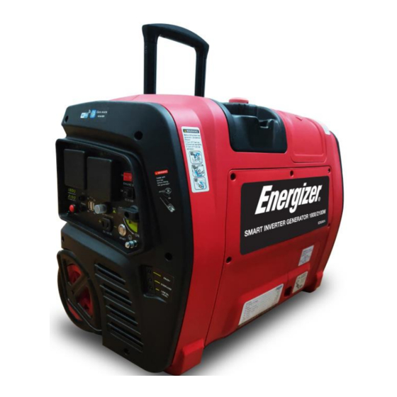
Page 30: Unit Description
ORIGINAL INSTRUCTIONS 3. UNIT DESCRIPTION 3.1 COMPONENTS IDENTIFICATION - 30 -... - Page 31 ORIGINAL INSTRUCTIONS (1). Control Panel: Location of generator controls and output receptacles. (2). Fuel Cap: Access to fuel tank for filling. (3). Fuel Cap Vent Lever: Control valve between atmosphere and fuel tank. (4). Carrying Handle: Lift the generator by this handle only. (5).
-
Page 32: Control Panel
ORIGINAL INSTRUCTIONS (17). Oil Cap: Access to fill or drain engine oil. (18). Air Intake Slats: Allow for cooling air to enter the housing. 3.2 CONTROL PANEL (1). Fuel Tap: Controls fuel supply to the carburetor. (2). AC Receptacles: AC Output receptacles for connecting AC devices. - 32 -... - Page 33 ORIGINAL INSTRUCTIONS (3). 12V DC Receptacle: Connection for re-charging 12V DC automotive-style batteries while generator is in operation. (4). 12V DC Circuit Breaker: Overload protection for the 12VDC charging system. (5). USB Plug: USB Output receptacles for connecting 5VDC devices. (6).
-
Page 34: Preparation
ORIGINAL INSTRUCTIONS you refill with oil, the engine will not start again. (14). POWER LED (optional): Lights up when the Gen-mate unit (optional equipment) inside the generator is operating normally. (15). Wi-Fi LED (optional): The light comes ON and flash slowly when the generator with Gen-mate unit (optional equipment) is connected to the Gen-mate APP in Smartphone by Wi-Fi. - Page 35 ORIGINAL INSTRUCTIONS - 35 -...
- Page 36 ORIGINAL INSTRUCTIONS Add Engine Oil: (1). Open the Oil Maintenance Cover 1, and remove the Oil Cap 2. (2). Fill the specified amount of the recommended engine oil, and then install and tighten the Oil Cap. NOTE ⚫ Make certain the generator is on a flat, level surface. ⚫...
-
Page 37: Fuel
ORIGINAL INSTRUCTIONS 4.2 FUEL ⚫ Gasoline is extremely flammable and explosive under certain conditions. Do not smoke or allow flames or sparks where the generator is refueled or where gasoline is stored. ⚫ Refuel in a well-ventilated area with the engine stopped. ⚫... - Page 38 ORIGINAL INSTRUCTIONS (2). The fuel level in the fuel tank can be checked through the Fuel Gauge 3. (3). After fill the fuel, make sure the Fuel Cap 1 is tightened securely. NOTE ⚫ Use only unleaded gasoline. The use of leaded gasoline will cause severe damage to internal engine parts.
-
Page 39: Starting The Engine
ORIGINAL INSTRUCTIONS 5. STARTING THE ENGINE 5.1 CHECK ENGINE OIL Check the oil BEFORE EACH USE with the generator on a level surface and the engine stopped. RECOMMENDED OIL: 4-stroke engine oil, SAE 10W-40, API SE/SF/SG/SH/SJ or higher. - 39 -... - Page 40 ORIGINAL INSTRUCTIONS Loosen (1). Open the Oil Maintenance Cover 1. (2). Remove the Oil Cap 2 and wipe the Dipstick 3 clean. (3). Check the oil level by inserting the Dipstick 3 into the filler neck without screwing it in. (4).
-
Page 41: Check Fuel
ORIGINAL INSTRUCTIONS ⚫ When the engine shuts down automatically by the low oil protection, the LOW OIL LEVEL LED (yellow) will come on, and unless you refill with oil, the engine will not start again. 5.2 CHECK FUEL ⚫ Do not smoke or allow flames or sparks where the generator is refueled or where gasoline is stored. -
Page 42: Open The Fuel Cap Vent Lever
ORIGINAL INSTRUCTIONS (2). Refuel if necessary. (3). After fill the fuel, make sure the Fuel Cap is tightened securely. (4). Check generator for fuel leakage. NOTE ⚫ Use only unleaded gasoline. ⚫ Never use an oil/gasoline mixture. ⚫ Fuel tank capacity: 4.2L. ⚫... -
Page 43: Open The Fuel Tap
ORIGINAL INSTRUCTIONS Turn the Fuel Cap Vent Lever 1 to “ON” position. "ON" position "OFF" position 5.4 OPEN THE FUEL TAP Turn the Fuel Tap 1 to “ON” position. - 43 -... -
Page 44: The Engine Switch & Eco Switch
ORIGINAL INSTRUCTIONS "ON" position "OFF" position 5.5 THE ENGINE SWITCH & ECO SWITCH (1). Turn the Engine Switch (Red) 1 to “ON” position. - 44 -... -
Page 45: Use Choke
ORIGINAL INSTRUCTIONS (2). Turn the ECO Switch (Black) 2 to “OFF” position. "ON" position "OFF" position 5.6 USE CHOKE Pull the Choke Knob 1 fully out to "START" position. - 45 -... - Page 46 ORIGINAL INSTRUCTIONS "RUN" position "START" position NOTE ⚫ The Choke is not required to start a warm engine. Push the Choke Knob into the "RUN" position. Usually keep the Choke Knob in "START" position for only 2 ⚫ pulls of the recoil starter or 2 pushes of the electric start button. After second pull or push, push Choke Knob into the "RUN"...
-
Page 47: Start The Engine
ORIGINAL INSTRUCTIONS 5.7 START THE ENGINE ⚫ Exhaust fumes contains poisonous carbon monoxide(CO), a colorless and odorless gas. Breathing CO can cause loss of consciousness and may lead to death. ⚫ Operate the generator in a well-ventilated area. Never run your generator inside a garage or house, even if door or window is open. - Page 48 ORIGINAL INSTRUCTIONS Recoil Start: Pull the Starter Grip 1 slowly until resistance is felt and then pull rapidly. NOTE Do not allow the Starter Grip to snap back against the generator. ⚫ Return it gently to prevent damage to the starter or housing. ⚫...
- Page 49 ORIGINAL INSTRUCTIONS Electric Start (optional): Push the Start Button 1 to the end and then release it. NOTE Open the Oil Maintenance Cover to connect the Battery ⚫ Connector 1 before using the electric starter (optional). - 49 -...
- Page 50 ORIGINAL INSTRUCTIONS ⚫ Normally the engine can be started within three pushes with electric starter. Keep the Choke Knob in "START" position for only 2 pushes. After second push, push the Choke Knob into the “RUN” position for up to the next 3 pushes. The electric starter (optional equipment) is equipped with an ⚫...
-
Page 51: Close Choke
ORIGINAL INSTRUCTIONS 5.8 CLOSE CHOKE After starting the engine, push the Choke Knob 1 fully into the “RUN” position. "RUN" position "START" position - 51 -... -
Page 52: Ac Operation
ORIGINAL INSTRUCTIONS NOTE Wait a few seconds until the engine speed is stable before closing the choke, and more time waiting if weather is cold. 6. AC OPERATION - 52 -... -
Page 53: Use The Generator
ORIGINAL INSTRUCTIONS 6.1 USE THE GENERATOR: After starting the engine, let it run for 2 or 3 minutes to warm up, then you can use the generator as follows: (1). Make sure the READY LED (green) 4 comes on. (2). Turn the ECO Switch 1 to "ON" position to use Economy Control System. - Page 54 ORIGINAL INSTRUCTIONS ⚫ Be sure to ground (Earth) the generator when the electric appliance is earthed. NOTE ⚫ The ECO Switch 1 must be turned to “OFF” position when using electric devices that require a large starting current, such as a heavy compressor or some high electrical loads. ⚫...
-
Page 55: Shut Down The Generator
ORIGINAL INSTRUCTIONS goes off after a few seconds. 6.2 SHUT DOWN THE GENERATOR: Once the generator is no longer needed it can be shut down: (1). Disconnect or turn off all electrical loads connected to the - 55 -... - Page 56 ORIGINAL INSTRUCTIONS generator AC Receptacles 1. (2). Turn the Fuel Tap 2 to the “OFF” position. (3). Turn the Engine Switch 3 to “OFF” position. (4). then turn the Fuel Cap Vent Lever 4 Allow the engine to cool well, to “OFF”...
- Page 57 ORIGINAL INSTRUCTIONS "ON" position "OFF" position NOTE ⚫ Generator equipped with Gen-mate unit (optional equipment) can be shut down by Gen-mate APP in smartphones, if using the APP, the above step 2/3 is unnecessary, but step 2/4 should be done before tilting or storing the generator. - 57 -...
-
Page 58: Dc Operation
ORIGINAL INSTRUCTIONS ⚫ TURN OFF all electrical loads connected to the generator AC Receptacles 1 before shutting down by Gen-mate APP in smartphones. ⚫ Always allow the generator to cool off before moving or storing. High temperature will be present at the rear of the unit for some time after shutdown. -
Page 59: Connecting The Battery Charging Cable
ORIGINAL INSTRUCTIONS acid solution that can cause severe burns. Avoid contact with skin, eyes or clothing. If a spill occurs, flush area with clear water immediately. 7.1 CONNECTING THE BATTERY CHARGING CABLE: (1). Before connecting the Battery Charging Cable 1 to a battery that is installed in a vehicle, disconnect the vehicle battery ground cable from the negative (-) battery terminal. - Page 60 ORIGINAL INSTRUCTIONS (6). Charging time will vary with battery size and condition. The DC Circuit Breaker 6 does not prevent over-charging a battery. NOTE ⚫ The 12V DC Receptacle should ONLY be used for charging 12V automotive type batteries. The 12V DC output is unregulated and will damage other 12V DC products.
-
Page 61: Disconnecting The Battery Charging Cable
ORIGINAL INSTRUCTIONS 7.2 DISCONNECTING THE BATTERY CHARGING CABLE: (1). Turn the Engine Switch to “OFF” position to stop the engine. (2). Disconnect the Black Charger Jack of the Battery Charging Cable from the negative (-) battery terminal. (3). Disconnect the Red Charger Jack of the Battery Charging Cable from the positive (+) battery terminal. - Page 62 ORIGINAL INSTRUCTIONS ⚫ The generator is allowed to be tilted down, but ONLY lay on the Drawbar Side 1. If lay down on other side, OIL may leak and damage the engine or your property. Also FUEL may leak and cause FIRE or an EXPLOSION.
-
Page 63: Maintenance
ORIGINAL INSTRUCTIONS ⚫ Keep all cooling holes open and clear of debris, mud, water, etc. Cooling holes are located on the front panel and the back cover of generator. If the cooling holes are blocked, the generator may overheat and damage the engine, inverter, or windings. ⚫... - Page 64 ORIGINAL INSTRUCTIONS authorized dealer for further attention. Maintenance Schedule Regular Service Period (5) Every 6 Every 1 Every 2 Each months year or years or or 50 100 hrs. 300 hrs. Item hrs. Check level ⊙ Engine oil Change ⊙(1) Air cleaner Clean ⊙(2)
-
Page 65: Engine Oil Change
ORIGINAL INSTRUCTIONS (2). Service more frequently when used in dusty areas. (3). These items should be serviced by your servicing dealer, unless you have the proper tools and are mechanically proficient. (4). Replace fuel line if necessary every 2 years. (5). - Page 66 ORIGINAL INSTRUCTIONS Ø30mm UPPER LIMIT LOWER LIMIT Drain the used oil while the engine is warm. Warm oil drains quickly and completely. (1). Turn OFF the Fuel Tap, Close the Fuel Cap tightly and turn OFF the Fuel Cap Vent Lever to reduce the possibility of fuel leakage. (2).
-
Page 67: Air Cleaner Service
ORIGINAL INSTRUCTIONS 4 that its diameter is about 30mm. (5). Set fully the paper Pipe 4 outside of the Oil Filler Neck 5, and drain the used oil into the Container 3 by tipping the engine toward the Oil Filler Neck 5. (6). - Page 68 ORIGINAL INSTRUCTIONS Using gasoline or flammable solvent to clean the air filter can cause a fire or explosion. Use only soapy water or nonflammable solvent. NOTE Operating the engine without an air filter, or with a damaged air filter, will allow dirt to enter the engine, causing rapid engine wear. This type of damage is not covered by the Distributor’s Limited Warranty.
-
Page 69: Spark Plug Service
ORIGINAL INSTRUCTIONS (1). Loosen five screws and remove the Maintenance Cover 1. (2). Loosen the Cover Screw 2 and remove the Air Filter Cover 3. (3). Wash the Sponge 4 in a solution of household detergent and warm water, then rinse thoroughly, or wash in nonflammable or high flash point solvent. - Page 70 ORIGINAL INSTRUCTIONS Loosen (1). Unscrew the screw 5, and then remove the Spark Plug Maintenance Cover 1. (2). Remove the Spark Plug Cap 2. (3). Use a Spark Plug Wrench 4 to remove the Spark Plug 3. (4). Inspect the Spark Plug 3. Replace it if the electrodes are worn or if the insulator is cracked, chipped, or fouled.
- Page 71 ORIGINAL INSTRUCTIONS (5). Measure the spark plug electrode gap with a wire-type feeler gauge. Correct the gap, if necessary, by carefully bending the side electrode. The gap should be: 0.024-0.028 in (0.60-0.70 mm) or 0.027-0.031 in (0.70-0.80 mm) according to Spark Plug type in SPECIFICATIONS. (6).
-
Page 72: Spark Arrester Maintenance
ORIGINAL INSTRUCTIONS NOTE A loose spark plug can overheat and damage the engine. Over tightening the spark plug can damage the threads in the cylinder head. 9.4 SPARK ARRESTER MAINTENANCE NOTE If the generator has been running, the muffler will be very hot. ⚫... - Page 73 ORIGINAL INSTRUCTIONS Screen A Screen B Clean the Spark Arrester 1 as follows: (1). Remove the five screws, and remove the Back Cover 2. (2). Remove the Spark Arrester 1. (3). Use a brush to remove carbon deposits from the Screen A and B. (4).
-
Page 74: Cleaning Fuel Tank Filter
ORIGINAL INSTRUCTIONS (5). Reinstall the Spark Arrester 1, and the Back Cover 2. 9.5 CLEANING FUEL TANK FILTER Never use the gasoline while smoking or in the vicinity of an open flame. - 74 -... -
Page 75: Transportation And Storage
ORIGINAL INSTRUCTIONS (1). Remove the Fuel Cap 1 and Fuel Tank Filter 2. (2). Clean the Fuel Tank Filter 2 with gasoline. If damaged, replace it. (3). Wipe the Fuel Tank Filter 2 and install it. (4). Install the Fuel Cap 1 securely. 10. -
Page 76: Drain The Fuel From The Carburetor
ORIGINAL INSTRUCTIONS (3). Close the Fuel Cap tightly. (4). Turn OFF the Fuel Cap Vent Lever. ⚫ DO NOT turn the Fuel Cap Vent Lever to “OFF” position before cooling the engine. Allow the engine to cool well, if not, the fuel tank can be crushed by cold contraction of the fuel gas in the fuel tank. - Page 77 ORIGINAL INSTRUCTIONS Five screws Loosen (1). Turn the Fuel Tap 5 to the “OFF” position. (2). Loosen five screws and remove the Maintenance Cover 4. (3). Take out the Drain Hose 1 from the hole at the bottom casing, and put it into a suitable container.
-
Page 78: Drain The Fuel From Fuel Tank
ORIGINAL INSTRUCTIONS (5). Drain the gasoline from the Carburetor 2 into the container through the Drain Hose 1. (6). Tighten the Drain Screw 3 clockwise securely. 10.2 DRAIN THE FUEL FROM FUEL TANK (1). Unscrew the Fuel Cap, remove the Fuel Tank Filter. (2). -
Page 79: Drain The Fuel From The Carburetor Again
ORIGINAL INSTRUCTIONS 10.3 DRAIN THE FUEL FROM THE CARBURETOR AGAIN Tighten (1). Turn the Fuel Cap Vent Lever to “ON” position. (2).Turn the Fuel Tap to the “ON” position. (3). Put the Drain Hose 1 into a suitable container. (4). Loosen the Drain Screw 3 counterclockwise. (5). -
Page 80: Engine
ORIGINAL INSTRUCTIONS ⚫ Gasoline is highly flammable and explosive. ⚫ Keep heat, sparks, and flame away. ⚫ Handle fuel only outdoors. ⚫ Wipe up spills immediately. 10.4 ENGINE (1). While engine is still warm, drain oil from crankcase. Refill with the recommended new oil. - Page 81 ORIGINAL INSTRUCTIONS Is there fuel in the tank? Refill the fuel tank Are the engine switch and fuel Turn the two switches on tap ON? Is the fuel cap vent lever ON? Turn the fuel cap vent lever on Does the choke knob pull out? Pull choke knob completely...
- Page 82 ORIGINAL INSTRUCTIONS Engine starts, then shuts down: Is the fuel level low? Add fuel to tank Is fuel cap vent lever closed? Open fuel cap vent lever Is engine oil level incorrect? Check engine oil level, add or drain as needed Is the fuel in the fueltank Replace fuel in the fueltank, contaminated?
- Page 83 ORIGINAL INSTRUCTIONS Engine starts, then runs rough: Is the choke stuck or left on? Turn choke to run position Is the air cleaner dirty or Clean or replace the air filter clogged? element Is the spark plug defective or Replace or clean spark plug dirty? Contact with an authorized dealer...
- Page 84 ORIGINAL INSTRUCTIONS No AC output: Is the generator overloaded? Reduce loads and push reset button to reset module Is AC voltage low? Verify the choke is on run position, and check fuel in the fueltank and carburetor, and check air filter Is the electrical device short Verify condition...
- Page 85 ORIGINAL INSTRUCTIONS No DC output Is the DC voltage low? Verify ECO Switch is on the "0" OFF position Is the DC circuit protector Push the DC circuit protector OFF? Check the electrical appliance Change replace for any fault appliance Contact with an authorized dealer - 85 -...
- Page 86 ORIGINAL INSTRUCTIONS Fuel leaks from drain hoses. Is the pressure in fueltank too Open fueltank vent to balance high? pressure Is the carburetor drain in bowl Turn drain screw clockwise to not closed? close Turn off the fuel tap Is the fuel tap not closed while tilting the generator? Contact with an authorized dealer...
-
Page 87: Specifications
ORIGINAL INSTRUCTIONS 12. SPECIFICATIONS EZG2001I SPECIFICATIONS DIMENSIONS AND WEIGHT Overall Length 530mm (20.9 in) Overall Width 320mm (12.6 in) Overall Height 430mm (16.9 in) Dry Weight 24kg (52.9 lbs) ENGINE Type 4-stroke gasoline OHV Cooling System Forced air Cylinder Arrangement... - Page 88 ORIGINAL INSTRUCTIONS Engine Oil Capacity 0.35L (0.37 US qt) Ignition System Starting System Recoil / Electric starter Type A5RTC (TORCH) Spark Plug 0.6~0.7mm (0.024~0.028in) dB(A) sound pressure level L =70.25 Noise Power Level(L sound power level L =90.25dB(A) K=1.56dB(A) @ From 4m by CE standards Guarantee sound power level: 92dB(A) GENERATOR Output Waveform...
- Page 89 ORIGINAL INSTRUCTIONS Output Rated Current 5V/2A/1A Safety Device Type DC Protector Degree of protection: IP23M 40 degrees Max temperature: Performance class: Quality class: Rated power factor: Max altitude: 1000m NOTE (1). EZG2001IE with recoil starter & electric starter. (2). The generator output specifications are based on the standard environment as follows: ⚫...
-
Page 90: Wiring Diagram
ORIGINAL INSTRUCTIONS 13. WIRING DIAGRAM - 90 -... -
Page 91: Environment Correction
ORIGINAL INSTRUCTIONS 14. ENVIRONMENT CORRECTION The rated power output is based on the standard condition as follows: ⚫ Ambient temperature: 25℃ ⚫ Relative humidity: 30% Factor of environment correction C: Ambient temperature℃ Altitude(m) 0.98 0.96 0.93 0.90 0.93 0.91 0.89 0.87 0.84 1000... - Page 92 ORIGINAL INSTRUCTIONS Example: Generator rated power P =1.8kVA, Altitude:1000m, Ambient temperature: 35℃, Relative humidity: 80%, Actual power P: *(C-0.02)=1.8*(0.82-0.02)=1.44kVA - 92 -...
- Page 93 ORIGINAL INSTRUCTIONS The manufacturer warrants the product against defects in materials and workmanship for a period of 2 years from the date of purchase to the original purchaser. The guarantee applies when the product is used as a home tool. The warranty does not extend for failures due to normal wear and tear.
- Page 94 ORIGINAL INSTRUCTIONS Nor does the guarantee extend to: • Cost of freight and packaging. • The use of the tool for any other purpose than for which it was designed • Use and maintenance of the machine in a manner not described in the user's manual.
- Page 95 ORIGINAL INSTRUCTIONS You need to create a "ticket" via their platform. • Login or create your account • Put your tool reference • Choose the subject of your request • Explain your problem • Attach these files: the invoice or receipt, the nameplate picture (serial number), the picture of the part you need (For example: pins on the transformer plug that broke away) We offer you a warranty extension to 1 year.
- Page 96 BUILDER SAS ZI, 32 RUE ARISTIDE BERGES – 312070 CUGNAUX – FRANCE Declares that the machinery designated below: Inverter Generating set Model: EZG2001i Serial number: Complies with the provisions of the Directive “machinery” 2006/42/EC and national laws transposing it: Also complies with the following European directives:...
- Page 97 ORIGINAL INSTRUCTIONS Measured sound power level, LwA: 90,25 dB, K = 1,56 dB (A) Guaranteed Sound power level: 92 dB (A) Responsible for the technical file: Michel Krebs Cugnaux, 15/02/2019 Philippe MARIE / PDG - 97 -...
Need help?
Do you have a question about the EZG2001i and is the answer not in the manual?
Questions and answers