
Related Manuals for Stryker Medical 700 Transport Gurney


Summary of Contents for Stryker Medical 700 Transport Gurney
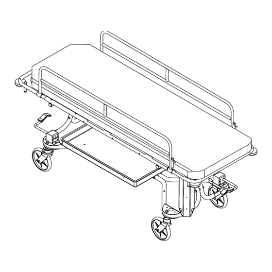
- Page 1 IMPORTANT File in your maintenance records 700 Transport Gurney OPERATIONS AND MAINTENANCE MANUAL For Parts or Technical Assistance: 1–800–327–0770...
-
Page 2: Table Of Contents
Table of Contents Introduction Specifications ............... Warning / Caution / Note Definition . -
Page 3: Introduction
Introduction INTRODUCTION This manual is designed to assist you with the operation and maintenance of the 700 Transport Gurney. Read it thoroughly before using the equipment or beginning any maintenance on it. SPECIFICATIONS Maximum Weight Capacity 500 pounds Overall Length/Width 78”/28”... -
Page 4: Operation Guide
Operation Guide Fowler Brace Handle (Not Shown) OPERATING BRAKE/STEER PEDALS The Brake/Steer pedals (A) are located at the patient’s head end, right and foot end, left. To engage the brake, push fully down on the pedal. To engage the steer caster, lift fully up on the pedal. -
Page 5: Using Folddown Siderails
Operation Guide USING FOLDDOWN SIDERAILS CAUTION Be sure the siderail latching mechanism is working properly at all times. If it is not, refer to page 7 for siderail latch adjustment. To engage siderails: Pull up siderail and raise to full up position so that latch engages. To disengage siderails: Pull up on latch and guide siderail to the full down position. -
Page 6: Operating Optional Removable I.v. Pole
Operation Guide OPERATING OPTIONAL REMOVABLE I.V. POLE Insert the I.V. pole into one of the four receptacles on the corner of the litter frame (A). Turn knob (B) counterclock– wise to loosen it. Grasp the top section (C) of the pole and raise or lower it to the desired height. -
Page 7: Preventative Maintenance
Preventative Maintenance CLEANING 1. Hand wash all surfaces of the bed with warm water and mild detergent. Dry thoroughly. 2. Clean Velcro AFTER EACH USE. Saturate Velcro with disinfectant and allow disinfectant to evaporate. (Appropriate disinfectant for nylon Velcro should be determined by the hospital.) NOTE Quaternary Germicidal Disinfectants, used as directed, and/or Chlorine Bleach products, typically 5.25% So- dium Hypochlorite in dilutions ranging between 1 part bleach to 100 parts water, and 2 parts bleach to 100... -
Page 8: Service Information
Service Information FOLDDOWN SIDERAIL LATCH ADJUSTMENT Required Tools: 1/8 Hex Allen Wrench WARNING The siderail latch adjustment is pre–set at the factory, and there should not normally be a need for readjust- ment. If adjustment must be done it is important to follow the procedure below. If it is not done properly, injury to the patient or user could occur. - Page 9 700–1–10 Base Assembly...
-
Page 10: 700-1-10 Base Assembly
700–1–10 Base Assembly Item Part No. Part Name Qty. 700–1–50 Base Tube Weldment 37–81 Tube Plug 700–1–4 Base Tube Spacer 37–59 Hole Plug 390–38–3 Curved Washer 3–11 Hex Hd. Cap Screw 16–36 Fiberlock Nut (page 12) Steer Lock Caster Ass’y (page 11) Caster Assembly 16–57... -
Page 11: 700-15-10 Brake Subassembly
700–15–10 Brake Subassembly Item Part No. Part Name Qty. 700–15–43 Follower Rod 26–11 Roll Pin 38–288 Compression Spring 700–15–29 Flange Bushing 700–15–38 Anti–Rotation Bracket 38–293 Compression Spring 700–15–50 Brake Ring Weldment... -
Page 12: 700-12-10 Caster Assembly
700–12–10 Caster Assembly Item Part No. Part Name Qty. 715–2–16 Caster Horn w/ Brg. Ass’y 715–2–25 Caster Wheel 16–60 Hex Nut 3–99 Hex Bolt 3–102 Hex Bolt... -
Page 13: 700-10-10 Steerlock Caster Assembly
700–10–10 Steerlock Caster Assembly Item Part No. Part Name Qty. 700–10–50 Steerlock Weldment 715–2–25 Caster Wheel 16–60 Hex Nut 3–99 Hex Bolt 3–102 Hex Bolt... -
Page 14: 700-30-10 Litter Assembly
700–30–10 Litter Assembly Item Part No. Part Name Qty. Item Part No. Part Name Qty. 700–30–44 Litter Side Tube 700–32–42 LCT Bracket, Left 700–32–44 Litter Cross Brace 700–32–41 LCT Bracket, Right 18–24 Tube Connector 81–241 Flange Bushing 390–38–3 Formed Washer 11–2 Flat Washer 3–11... -
Page 15: 700-25-10 Folddown Siderail Assembly
700–25–10 Folddown Siderail Assembly Litter Assembly p/n 700–30–10 (Ref.) Item Part No. Part Name Qty. 700–25–50 Folddown Siderail Weldment (page 15) Siderail Assembly 721–26–69 Upright Sleeve 721–26–66 Pivot Screw 4–136 But. Hd. Cap Screw 37–74 Hole Plug 721–26–74 Lock Handle, Machined 38–220 Compression Spring 1010–26–80... -
Page 16: 1010-26-17 Siderail Assembly
1010–26–17 Siderail Assembly Item Part No. Part Name Qty. 1010–26–15 Top Rail 1010–26–83 Upright 1010–26–84 Upright, Bent 1010–26–82 Sleeve Bearing 25–106 Semi–Tubular Rivet 1010–26–10 Round Hole Plug 1010–26–85 Upright, Latch 1010–26–12 Bent Spindle Rest... -
Page 17: 700-20-10 Swingdown Siderail Assembly
700–20–10 Swingdown Siderail Assembly Litter Assembly p/n 700–30–10 (Ref.) Item Part No. Part Name Qty. 700–20–50 Swingdown Siderail Wldmt. 390–3–33 Compression Spring 26–14 Roll Pin 38–110 Compression Spring 26–216 Roll Pin 700–20–38 Lock Pin Guide Cap 26–6 Roll Pin 700–20–39 Siderail Lock Pin 700–20–35 Label, Release... -
Page 18: 700-120-10 Storage Tray Assembly
700–120–10 Storage Tray Assembly Base Assembly p/n 700–1–10 (Ref.) Item Part No. Part Name Qty. 700–120–45 Storage Tray 700–120–44 Storage Tray Supt. Tube 4–163 But. Hd. Cap Screw 4–135 But. Hd. Cap Screw 11–2 Flat Washer 16–28 Fiberlock Nut 470–2–4 Nylon Spacer 946–1–108 I.V. -
Page 19: 700-140-10 Oxygen Bottle Holder Assembly
700–140–10 Oxygen Bottle Holder Assembly HEAD END Base Assembly p/n 700–1–10 (Ref.) Item Part No. Part Name Qty. 700–140–45 Oxygen Bottle Holder 4–204 But. Hd. Cap Screw 16–28 Fiberlock Nut 11–2 Flat Washer 700–140–44 Bottle Holder Strap 4–57 But. Hd. Cap Screw 16–27 Fiberlock Nut 11–16... -
Page 20: 390-25 I.v. Pole Assembly
390–25 I.V. Pole Assembly 700–142–10 I.V. Holder Mounting Kit 390–25 700–142–10 Item Part No. Part Name Qty. 4–26 Soc. Hd. Cap Screw 946–1–108 I.V. Clip 11–53 Flat Washer Item Part No. Part Name Qty. 11–3 Flat Washer 721–26–66 Pivot Screw 24–23 Plastic Knob 26–199... -
Page 21: 741-34 Foot Board/Chartholder Assembly
741–34 Foot Board/Chartholder Assembly Item Part No. Part Name Qty. 946–28–11 Chart Holder 741–29–18 Head/Foot Board * Replacement Part Number 741–34–100... -
Page 22: 741-48-14 Defibrillator Tray Assembly
741–48–14 Defibrillator Tray Assembly Item Part No. Part Name Qty. Item Part No. Part Name Qty. 946–39–4 Tray 741–48–12 Label 926–39–16 Crosstube 390–57–12 Long Strap 25–55 Rivet 390–57–13 Short Strap 926–39–9 Cover 946–1–283 Label 18–6 Umbrella Nut 741–48–20 Holder 29–8 Dual Lock 2–44 Screw... -
Page 23: 1010-50-10 Foot Extension/Defibrillator Tray Assembly
Foot Extension/Defibrillator Tray Assembly Assembly part number 1010–50–210* Label Detail Label Detail Item Part No. Part Name Qty. Item Part No. Part Name Qty. 8–49 Socket Hd. Shoulder Bolt 1010–50–50 Knob 14–20 Nylon Washer 1010–50–57 “Max. Weight” Label 14–21 Nylon Washer 1010–50–205 Cushion Assembly 16–28... -
Page 24: Replacement Parts
Replacement Parts and Kits PART NAME PART NUMBER Ankle Restraint Straps ..........946–43 Body Restraint Straps . -
Page 25: Warranty
No employee or representative of Stryker is authorized to change this warranty in any way. Stryker Medical stretchers are designed for a 10 year expected life under normal use conditions and appropri- ate periodic maintenance as described in the maintenance manual for each device. -
Page 26: Return Authorization
Warranty Return Authorization: Merchandise cannot be returned without approval from the Stryker Customer Service Department. An autho- rization number will be provided which must be printed on the returned merchandise. Stryker reserves the right to charge shipping and restocking fees on returned items. SPECIAL, MODIFIED, OR DISCONTINUED ITEMS NOT SUBJECT TO RETURN. - Page 27 6300 Sprinkle Road, Kalamazoo, MI 49001–9799 (800) 327–0770 DH 3/97 700–90–1 REV H...
Need help?
Do you have a question about the 700 Transport Gurney and is the answer not in the manual?
Questions and answers