Stryker Medical Renaissance Series Maintenance Manual
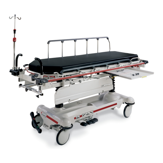
Extended stay stretcher
Hide thumbs
Also See for Renaissance Series:
- Maintenance manual (123 pages) ,
- Operation manual (19 pages) ,
- Maintenance manual (65 pages)

Subscribe to Our Youtube Channel
Related Manuals for Stryker Medical Renaissance Series


Summary of Contents for Stryker Medical Renaissance Series
- Page 1 IMPORTANT File in your maintenance records Renaissance Series 1050/1550 Extended Stay Stretcher MAINTENANCE MANUAL For Parts or Technical Assistance: 1–800–327–0770...
-
Page 2: Table Of Contents
Table of Contents Introduction Specifications ................Warning / Caution / Note Definition . - Page 3 Table of Contents Assembly Drawings and Parts Lists (Continued) Jack Assembly, Non–Electric Lift Base ............Jack Base Assembly, Non–Electric Lift Base .
-
Page 4: Introduction
Introduction INTRODUCTION This manual is designed to assist you with the maintenance of the 1050/1550 Synergy Series Extended Stay Stretcher. Read it thoroughly before using the equipment. SPECIFICATIONS 1050 1550 Maximum Weight Capacity 500 pounds 500 pounds Overall Bed Length/Width 83.5”/31”... -
Page 5: Preventative Maintenance
Preventative Maintenance CHECKLIST (PERFORM A MINIMUM OF BIANNUALLY) All fasteners secure (reference all assembly prints) Siderails move and latch properly (page 5) All casters lock with brake pedal engaged (page 15) Steer function working properly All casters secure and swivel properly Body restraints working properly I.V. -
Page 6: Cleaning
Cleaning Clean Velcro AFTER EACH USE. Saturate Velcro with disinfectant and allow disinfectant to evaporate. (Ap- propriate disinfectant for nylon Velcro should be determined by the hospital.) In general, when used in those concentrations recommended by the manufacturer, either phenolic type or quaternary type disinfectants can be used with Staph–Chek fabrics. - Page 7 Notes...
-
Page 8: Service Information
Service Information SIDERAIL LATCH ADJUSTMENT Required Tools: 1/8 Hex Allen Wrench WARNING The siderail latch adjustment is pre–set at the factory, and there should not normally be a need for readjust- ment. If adjustment must be done it is important to follow the procedure below. If it is not done properly, injury to the patient or user could occur. -
Page 9: Pedal Linkage Adjustment
Service Information PEDAL LINKAGE ADJUSTMENT – DUAL SIDE CONTROL BASE... -
Page 10: Caster Assembly Replacement
Service Information CASTER ASSEMBLY REPLACEMENT... -
Page 11: Caster Maintenance
Service Information CASTER MAINTENANCE... - Page 12 Notes...
-
Page 13: Caster Cover Installation And Removal
Service Information CASTER COVER INSTALLATION AND REMOVAL Looking through the larger of the two side cut–outs, align cover with axle nut or bolt head, as shown. Double Prongs Push down on the opposite side of the cover until single prong engages with caster horn. Single Prong Top View (Cut–Away) Properly Attached... -
Page 14: Troubleshooting
Service Information HYDRAULIC SYSTEM TROUBLESHOOTING NOTE Be sure the pedal linkage has been adjusted properly before beginning service on the jacks (see page 6). PROBLEM/SYMPTOM SOLUTION Jack will not raise to full height. Check for leaks. Add hydraulic fluid (see p. 10). Jack will not hold in raised position. -
Page 15: Checking Hydraulic Fluid Level
Service Information CHECKING HYDRAULIC FLUID LEVEL Required Tools: 3/8 Open End Wrench 3/4 Open End Wrench Procedure: WARNING To avoid personal injury or damage to the stretcher, remove the litter and the base hood before beginning service on the jacks. 1. -
Page 16: Jack Descent Rate Adjustment
Service Information JACK DESCENT RATE ADJUSTMENT Required Tools: Screwdriver Bungee Cords Adjustment Procedure: 1. Pump the litter up to full height. 2. Lift the base hood, separating the hood from the base frame. Using the bungee cords, support the base hood. -
Page 17: Hydraulic Check Valve Replacement - Non Electric Lift Base
Service Information HYDRAULIC CHECK VALVE REPLACEMENT – NON–ELECTRIC LIFT BASE Required Tools: 3/8 Box End Wrench Stiff Wire (with bent, pointed end) Small Needle Nose Pliers 3/4 Open End Wrench Torque Wrench (with Ft. Lbs. adjust.) 7/32 Hex Allen Wrench 1/2 Inch Diameter Rod Replacement of Valve #1 WARNING... -
Page 18: Replacement Of Valve #2
Service Information HYDRAULIC CHECK VALVE REPLACEMENT – NON–ELECTRIC LIFT BASE (CONTINUED) Replacement of Valve #2 WARNING To avoid personal injury or damage to the stretcher, remove the litter and the base hood before beginning service on the jacks. Lower the jack rod completely to relieve the pressure on the pump piston side of the jack. -
Page 19: Hydraulic Pressure Hose Replacement
Service Information HYDRAULIC PRESSURE HOSE REPLACEMENT 40” Hose Part Number 1550–71–1 36” Hose Part Number 1550–71–7 Required Tools: Large Phillips Screwdriver 9/16” Open End Wrench 11/16” Open End Wrench 6” 3/8 Drive Extension 3/8” Drive Ratchet Paper Towels or Rags String or Bungee Cord Modified Flair Nut Wrench –... -
Page 20: Brake Adjustment
Service Information BRAKE ADJUSTMENT... -
Page 21: Brake Cam Replacement
Service Information BRAKE CAM REPLACEMENT Brake Cam Part Number 715–1–213 Required Tools: Phillips Screwdriver String or Bungee Cord 3/32” Allen Wrench 1/8” Allen Wrench Procedure: 1. Unplug the power cord from the wall socket. 2. Remove the four Phillips screws holding the base hood to the frame. Lift and support the base hood using string or bungee cord. -
Page 22: Power Cord Replacement
Service Information BRAKE RING REPLACEMENT 7. Using needle–nose pliers, carefully squeeze and remove the spring between the brake cam and the brake ring. WARNING The spring is tightly compressed. Use caution when removing it or personal injury could result. 8. If you are working on an end control base, remove the spring from the pump pedal. 9. -
Page 23: Static Discharge Precautions
2 and 3 of the following procedure. Do not place unprotected circuit boards on the floor. All circuit boards to be returned to Stryker Medical should be shipped in the static shielding bags the new boards were shipped in. -
Page 24: Switch Replacement/Adjustment
Service Information SWITCH REPLACEMENT/ADJUSTMENT... -
Page 25: Jack/Motor Replacement
Service Information JACK/MOTOR REPLACEMENT Jack/Motor Assembly Part Number 1550–270–6, Jack Part Number 1550–270–5, Motor Part Number 1550–70–16, Capacitor Part Number 59–111 NOTE When replacing the foot end jack, the motor does not need to be removed. Required Tools: Large Phillips Screwdriver String or Bungee Cord Sawhorses (or equivalent) 1/2”... -
Page 26: Fowler Lift Motor/Actuator Replacement
Service Information JACK/MOTOR REPLACEMENT (CONTINUED) 16. Reinstall fill plug, plug stretcher power cord into a properly grounded wall receptacle and run the jack up and down electrically. Remove the fill plug and add more hydraulic fluid, if necessary. Repeat this step two or three times. - Page 27 Service Information FOWLER LIFT MOTOR/ACTUATOR REPLACEMENT (CONTINUED) 5. Using a screwdriver, pry off the ball retainers at each end of the black gas cylinder and remove the gas cylinder. Using a 5/32” Allen wrench, remove the screws (B) holding the stop (C) on each side of the Fowl- er tube (D).
-
Page 28: Gatch Lift Motor/Actuator Replacement
Service Information GATCH LIFT MOTOR/ACTUATOR REPLACEMENT Required Tools: 7/16” Socket Ratchet 1/4” Socket or Wrench Inclinometer 5/16” Socket 5/64” Allen Wrench 3” Extension Medium Standard Screwdriver 1/2” Wrench or Socket 1/2” Socket 5/32” Wrench (2) 7/16” Wrenches String or Cord Sawhorse (or equivalent) Procedure: 1. -
Page 29: Fowler And Knee Gatch Motor/Actuator Adjustment
Service Information FOWLER AND KNEE GATCH MOTOR/ACTUATOR ADJUSTMENT Procedure: 1. Electrically raise the Fowler and/or Knee Gatch until it stops. Use an inclinometer to check the angle of the Fowler/Knee Gatch. If the angle is not 70_– 80_ for the Fowler and 28_– 30_ for the Gatch, the actua- tor(s) will need to be adjusted. -
Page 30: Logic Circuit Board Replacement
Service Information LOGIC CIRCUIT BOARD REPLACEMENT Logic Circuit Board Part Number 1550–80–900 Required Tools: Standard Screwdriver 5/32” Allen Wrench 7/64” Allen Wrench Procedure: 1. Unplug the power cord from the wall socket. Properly ground yourself (see page 18). 2. Lift the foot section and pivot it back, securing it with a string or cord. Using a 5/32” Allen wrench, remove the four screws and two Knee Gatch guides from the sides of the motor/board enclosure cover. -
Page 31: Patient Control Lockout Led Replacement
Service Information PATIENT CONTROL LOCKOUT LED REPLACEMENT Required Tools: Standard Screwdriver 5/32” Allen Wrench Wire Cutters Procedure: 1. Unplug the power cord from the wall socket. Properly ground yourself (see page 18). 2. Lift the foot section and pivot it back, securing it with a string or cord. Using a 5/32” Allen wrench, remove the four screws and two Knee Gatch guides from the sides of the motor/board enclosure cover. -
Page 32: Replacement Parts
Replacement Parts ITEM PART NUMBER Brake Cam ............715–301–221 Brake Ring . -
Page 33: Base/Hood Assembly Without Electric Lift
Base/Hood Assembly Without Electric Lift... - Page 34 Base/Hood Assembly Without Electric Lift BASE FRAME TUBE GROUNDING SCHEMES Assembly part number 1550–201–1 Item Part No. Part Name Qty. Item Part No. Part Name Qty. 3–20 Hex Hd. Cap Screw 55–18 Threaded Insert 4–85 Soc. Hd. Cap Screw 59–75 Cable Tie 7–35 Truss Hd.
-
Page 35: Side Control Base Assembly (With Brakes)
Side Control Base Assembly (with Brakes) - Page 36 Side Control Base Assembly (with Brakes) Item Part No. Part Name Qty. 715–1–245 Base Weldment Assembly 38–211 Spring 715–1–158 Caster Nut 715–1–61 Caster Brake Assembly (page 32) Brake Adjuster Assembly 715–1–231 Brake/Steering Rod Assembly 1 1000–10–62 Steering Lock Linkage Bar (page 32) Brake Cam Assembly 715–1–94...
-
Page 37: Brake Adjuster Assembly
Brake Adjuster Assembly Assembly part number 715–1–150 Item Part No. Part Name Qty. 715–1–62 Threaded Stud Assembly 14–4 Nylon Washer 715–1–180 Bearing 28–8 Retaining Ring Brake Cam Assembly Assembly part number 715–1–213 Item Part No. Part Name Qty. 715–1–221 Brake Cam 16–59 Fiberlock Nut 8–21... -
Page 38: Caster Assembly With Steerlock
Caster Assembly with Steerlock Assembly part number 715–2–21 Item Part No. Part Name Qty. 700–10–50 Steer Lock Caster Weldment 715–2–25 Caster Wheel 16–60 Hex Nut 3–99 Hex Bolt 715–3–96 Hex Bolt 1000–59–10 Latch Assembly 11–310 Flat Washer... -
Page 39: Caster And Caster Cover Replacement Kits
Caster and Caster Cover Replacement Kits Item Part No. Part Name Qty. 715–2–20 Caster Assembly 715–1–266 Caster Cover, Left 715–1–265 Caster Cover, Right p/n 715–259–400 – Kit to replace 4 standard caster assemblies with hardware – no caster covers. p/n 715–269–400 – Kit to replace 3 standard caster assemblies and 1 steerlock caster with hardware – no caster covers. -
Page 40: Fifth Wheel Assembly
Fifth Wheel Assembly Assembly part number 715–1–25 Item Part No. Part Name Qty. 715–1–339 Fifth Wheel Pivot Assembly 715–1–17 Fifth Wheel Bushing 16–11 Flexlock Nut 715–1–15 Spring 715–1–13 Fifth Wheel Bracket 16–12 Flexlock Nut 390–1–54 Wheel 3–31 Hex Hd. Cap Screw 3–82 Hex Hd. -
Page 41: Side Control Base Assembly (With Jacks)
Side Control Base Assembly (with Jacks) Assembly part number 715–1–260... - Page 42 Side Control Base Assembly (with Jacks) Item Part No. Part Name Qty. 29–7 Dual Lock (page 40) Jack Assembly 11–262 Flat Washer 3–62 Hex Hd. Cap Screw 11–3 Flat Washer 16–36 Nylock Hex Nut 715–1–192 Jack Support 3–85 Hex Hd. Cap Screw 715–1–193 Jack Support Clamp 13–38...
- Page 43 Pedal Base Assembly, Pump Assembly part number 715–1–108 Item Part No. Part Name Qty. 715–1–83 Pedal Ass’t Wldmt., Pump 715–1–126 Side Control Pedal Pad 81–44 Bearing, Bronze NOTE Apply plastic adhesive to the mating surfaces of item B prior to assembly.
- Page 44 Pedal Base Assembly, Left Item Part No. Part Name Qty. 715–1–98 Release Pedal Eldmt., Hd. Lt. 721–40–25 Pedal Pedal Base Assembly, Right Item Part No. Part Name Qty. 715–1–97 Release Pedal Eldmt., Hd. Rt. 721–40–25 Pedal NOTE Apply plastic adhesive to the mating surfaces of item B prior to assembly.
-
Page 45: Jack Assembly, Non-Electric Lift Base
Jack Assembly, Non–Electric Lift Base Assembly part number 715–270–10 Item Part No. Part Name Qty. Item Part No. Part Name Qty. 45–904 Quad Ring 45–110 O–Ring 715–1–340 Cap Assembly 388–1–38 Plug 390–1–243 Gasket 715–1–322 Reservoir 715–1–323 Actuator Cylinder 390–1–244 Gasket 715–1–325 Actuator 390–1–238... -
Page 46: Jack Base Assembly, Non-Electric Lift Base
Jack Base Assembly, Non–Electric Lift Base Assembly part number 715–270–5 Item Part No. Part Name Qty. Item Part No. Part Name Qty. 1210–70–12 Jack Base 45–110 O–Ring 1210–70–13 Base Plug 715–1–328 Piston Wear Ring 715–270–1 14–50 Bearing Retainer 45–966 O–Ring 715–1–327 Cylinder Wear Ring 38–311... - Page 47 Assembly part number 1550–202–10...
- Page 48 Assembly part number 1550–202–10...
-
Page 49: Electric Lift Base Assembly
Electric Lift Base Assembly... - Page 50 Electric Lift Base Assembly Item Part No. Part Name Qty. Item Part No. Part Name Qty. 1–21 Flat Hd. Mach. Screw 52–245 Nyliner 2–19 Rd. Hd. Mach. Screw 52–263 Tubular Spacer 3–3 Hex Hd. Cap Screw 55–18 Threaded Insert 3–20 Hex Hd.
-
Page 51: Switch Assembly
Switch Assembly Assembly part number 1550–1–35 Item Part No. Part Name Qty. 1550–1–7 Bracket 59–78 Switch 4–141 Soc. Hd. Cap Screw 16–7 Fiberlock Nut... -
Page 52: Pump Connecting Rod Assembly
Pump Connecting Rod Assembly Assembly part number 1550–1–15 Item Part No. Part Name Qty. 715–1–27 Pump Connecting Rod 1550–1–8 Trigger Bracket 25–38 Pop Rivet... - Page 53 Jack & Pump/Motor Assembly, Electric Lift Base Assembly part number 1550–270–6 Item Part No. Part Name Qty. Item Part No. Part Name Qty. 1550–70–16 Pump/Motor 4–130 Hex But. Hd. Cap Screw 1550–1–52 Pump/Motor Bracket (page 50 & 51) Jack Assembly 1550–1–53 Pump/Motor Base 48–146...
- Page 54 VIEW A–A VIEW D–D VIEW C–C VIEW B–B...
-
Page 55: Jack Assembly, Electric Lift Base
Jack Assembly, Electric Lift Base Assembly part number 1550–270–5... - Page 56 Jack Assembly, Electric Lift Base Item Part No. Part Name Qty. 45–904 Quad Ring 1550–70–6 Cap Assembly 390–1–243 Gasket 1550–70–4 Actuator Cylinder 715–1–325 Actuator 45–14 O–Ring 926–20–161 Parker Packing 715–1–331 Piston End 926–20–162 Wear Ring 4–14 Soc. Hd. Cap Screw 45–110 O–Ring 388–1–38...
-
Page 57: Jack Base Assembly, Electric Lift Base
Jack Base Assembly, Electric Lift Base Item Part No. Part Name Qty. Item Part No. Part Name Qty. 1550–70–12 Jack Base, Machined 715–1–318 Pump Piston 715–1–308 Base Plug 45–110 O–Ring 715–1–306 715–1–328 Piston Wear Ring 28–8 Snap Ring 14–50 Bearing Retainer 390–2–176 Washer 715–1–327... -
Page 58: Base Labeling Assembly
Base Hood Labeling Assembly... - Page 59 Base Hood Labeling Assembly Item Part No. Part Name Qty. 11–16 Flat Washer 25–50 Pop Rivet 715–1–176 Oxygen Bottle Retainer 741–1–145 Brake/Steer Label, Head 741–1–146 Brake/Steer Label, Foot 921–1–252 Serial Number Tag 946–1–60 Stryker Logo Label 1050–90–2 Specification Label 1550–290–2 Specification Label 1550–90–13 Electric Shock Caution Label...
- Page 60 Stretcher Graphics Reference below for dept. label part numbers. Color Item A Control Item B Control Item C Stripe Item D Stripe Litter Bumper Label, Right Label, Left Label, Right Label, Left 1010–700–11 1010–700–12 1010–700–13 1010–700–14 1010–700–15 PURPLE 1010–700–21 1010–700–22 1010–700–23 1010–700–24 1010–700–25...
- Page 61 Assembly part number 1050–230–10 Detail of P.U.P. Liner...
-
Page 62: Litter Assembly
1050 Litter Assembly Assembly part number 1050–230–10 Gatch Drive Tube (Ref.) Fowler Drive Bar (Ref.) - Page 63 Assembly part number 1050–230–10...
- Page 64 Assembly part number 1050–230–10 Switch Cable p/n 1550–85–1 (Ref.) Head End Lockout Cable p/n 1550–85–18 (Ref.) Switch Cable p/n 1550–85–1 (Ref.) p/n 1550–85–30 Ground Strap Switch Cable p/n 1550–85–8 p/n 1550–85–1 (Ref.) Hd. Lockout Cable Fowler Motor Cable p/n 1550–85–1 Switch Cable Gatch Motor Cable p/n 1550–85–20 (for Powered Base)
- Page 65 1050 Litter Assembly Item Part No. Part Name Qty. Item Part No. Part Name Qty. 1050–30–5 Frame Assembly 3–41 Hex Hd. Cap Screw 938–1–401 Collar 1550–90–30 Litter Fuse Label 28–23 Retaining Ring 3–47 Hex Hd. Cap Screw 1001–40–12 Foot Board Receptacle 37–59 Hole Plug 23–104...
- Page 66 1050 Litter Assembly Item Part No. Part Name Qty. Item Part No. Part Name Qty. 1550–30–25 Power Cord Hook 1550–85–8 Hd. End Lockout Cable 1001–31–31 Pneumatic Fowler Rest 1550–33–31 Fowler Supt. Ass’y 23–100 Self–Tapping Screw 1550–90–5 Lockout Label 1550–34–20 Crankscrew Mtg. Brkt. 1550–90–13 Caution Label 1550–34–21...
- Page 67 Assembly part number 1550–230–10...
- Page 68 1550 Litter Assembly Assembly part number 1550–230–10...
- Page 69 Assembly part number 1550–230–10...
- Page 70 Assembly part number 1550–230–10 FOOT END...
- Page 71 1550 Litter Assembly Item Part No. Part Name Qty. Item Part No. Part Name Qty. 1550–30–5 Frame Assembly 721–26–66 Pivot Screw 938–1–401 Collar 721–26–69 Upright Sleeve 28–23 Retaining Ring 4–136 But. Hd. Cap Screw 1001–40–12 Foot Board Receptacle 4–135 But. Hd. Cap Screw 23–104 Self–Tapping Screw 38–220...
- Page 72 1550 Litter Assembly Item Part No. Part Name Qty. Item Part No. Part Name Qty. 946–1–60 Logo Label 460–2–32 Ground Strap 3–1 Hex Hd. Cap Screw 1510–34–90 Slider Pad 37–10 Hole Plug 946–1–155 Bumper 1010–254–4 Receptacle Ass’y, Lt. 988–2–676 Earth Ground Jumper 1010–254–6 Receptacle Ass’y, Rt.
-
Page 73: Fowler/Gatch Quick Drop Assembly
Fowler/Gatch Quick Drop Assembly... - Page 74 Fowler/Gatch Quick Drop Assembly Item Part No. Part Name Qty. 1050–33–28 Drive Bar Weldment 1550–33–14 Fowler Crkscr. Detent Ass’y 1550–33–25 Quick Drop Brkt. Ass’y, Rt. 1550–33–26 Quick Drop Brkt. Ass’y, Lt. 1050–33–19 Release Arm Weldment 1550–33–36 Right Release Label 1550–33–37 Left Release Label 1550–33–38 E–Drop Release Label, Left...
- Page 75 Fowler/Gatch Quick Drop Assembly 69.1...
- Page 76 Fowler/Gatch Quick Drop Assembly Item Part No. Part Name Qty. 1550–33–28 Drive Bar Weldment 1550–33–14 Fowler Crkscr. Detent Ass’y 1550–33–25 Quick Drop Brkt. Ass’y, Rt. 1550–33–26 Quick Drop Brkt. Ass’y, Lt. 1550–33–19 Release Arm Weldment 1550–33–20 Handle Guard 1550–33–36 Right Release Label 1550–33–37 Left Release Label 1550–33–38...
-
Page 77: Quick Drop Assembly, Fowler Only
Quick Drop Assembly, Fowler Only... - Page 78 Quick Drop Assembly, Fowler Only Item Part No. Part Name Qty. 1050–33–28 Drive Bar Weldment 1550–33–14 Fow. Crkscr. Detent Ass’y 1550–33–25 Quick Drop Brkt. Ass’y, Rt. 1550–33–26 Quick Drop Brkt. Ass’y, Lt. 1050–33–19 Release Arm Weldment 1550–33–20 Handle Guard 1550–33–36 Release Label, Rt.
- Page 79 Assembly part numbers 1550–37–10...
- Page 80 Quick Drop Assembly, Fowler Only Item Part No. Part Name Qty. 1550–33–28 Drive Bar Weldment 1550–33–14 Fow. Crkscr. Detent Ass’y 1550–33–25 Quick Drop Brkt. Ass’y, Rt. 1550–33–26 Quick Drop Brkt. Ass’y, Lt. 1550–33–19 Release Arm Weldment 1550–33–20 Handle Guard 1550–33–36 Release Label, Rt.
- Page 81 Notes 71.3...
- Page 82 Powered Fowler & Gatch Assembly Assembly part number 1550–36–10 Item Part No. Part Name Qty. (page 75) Fowler Crankscrew Ass’y (page 77) Gatch Crankscrew Ass’y 1550–33–54 Fowler Drive Bar Weldment 1550–33–55 Spacer 1550–90–33 Fowler Engage Label 1550–90–34 Gatch Engage Label 3–68 Hex Hd.
- Page 83 Powered Fowler & Gatch Assembly Assembly part number 1050–36–10 Item Part No. Part Name Qty. (page 75) Fowler Crankscrew Ass’y (page 77) Gatch Crankscrew Ass’y 1050–33–54 Fowler Drive Bar Weldment 1550–33–55 Spacer 1550–90–33 Fowler Engage Label 1550–90–34 Gatch Engage Label 3–68 Hex Hd.
-
Page 84: Push Handle Assembly
Push Handle Assembly Assembly part number 1211–151–10 Item Part No. Part Name Qty. 26–10 Roll Pin 1010–254–24 Stop Link 1211–151–18 Sleeve Assembly... -
Page 85: Fowler Crankscrew W/Actuator
Fowler Crankscrew Assembly w/Actuator Assembly part number 1550–33–30 Item Part No. Part Name Qty. Item Part No. Part Name Qty. 1550–34–13 Crk/Coupler Hsg. Ass’y, Rt. 1 26–149 Roll Pin 1550–34–1 Crank Coupler 26–179 Spiral Pin 38–286 Compression Spring 1550–1–16 Crank Handle 28–88 Snap Ring 1550–1–14... -
Page 86: Fowler Crankscrew Assembly, Non-Quick Drop
Fowler Crankscrew Assembly, Non–Quick Drop Assembly part number 1550–233–30 Item Part No. Part Name Qty. Item Part No. Part Name Qty. 1550–34–13 Crk/Coupler Hsg. Ass’y, Rt. 1 26–149 Roll Pin 1550–34–1 Crank Coupler 26–179 Spiral Pin 38–286 Compression Spring 1550–1–16 Crank Handle 28–299 Snap Ring... -
Page 87: Gatch Crankscrew W/Actuator
Gatch Crankscrew Assembly w/Actuator Assembly part number 1550–34–5 Item Part No. Part Name Qty. Item Part No. Part Name Qty. 1550–34–14 Crk/Coupler Hsg. Ass’y, Lt. 1 26–149 Roll Pin 1550–34–1 Crank Coupler 26–179 Spiral Pin 38–286 Compression Spring 1550–1–16 Crank Handle 28–88 Snap Ring 1550–1–14... -
Page 88: Gatch Crankscrew Assembly, Non-Quick Drop
Gatch Crankscrew Assembly, Non–Quick Drop Assembly part number 1550–234–5 Item Part No. Part Name Qty. Item Part No. Part Name Qty. 1550–34–14 Crk/Coupler Hsg. Ass’y, Lt. 1 26–149 Roll Pin 1550–34–1 Crank Coupler 26–179 Spiral Pin 38–286 Compression Spring 1550–1–16 Crank Handle 28–88 Snap Ring... -
Page 89: Siderail Assembly
Siderail Assembly, Left & Right Assembly part numbers FOOT END (REF.) 1550–26–20 (Left) & 1550–26–22 (Right) (RIGHT SIDERAIL IS SHOWN) See View P VIEW P Item Part No. Part Name Qty. 1550–26–21 Top Rail, Left 1550–26–23 Top Rail, Right 1010–26–83 Upright 1010–26–84 Upright, Bent... -
Page 90: Component Housing Assembly
Component Housing Assembly, Right Assembly part number 1550–26–16 Item Part No. Part Name Qty. 1550–26–14 Component Housing, Rt. 1550–80–930 Switch Board Assembly 1550–26–11 Lexan Shield 1550–26–25 Control Labels, Rt. 2–5 Round Hd. Screw... - Page 91 Component Housing Assembly, Left Assembly part number 1550–26–17 Item Part No. Part Name Qty. 1550–26–13 Component Housing, Lt. 1550–80–930 Switch Board Assembly 1550–26–11 Lexan Shield 1550–26–26 Control Labels, Lt. 2–5 Round Hd. Screw...
-
Page 92: 2-Stage I.v. Pole Mounting Assembly
2–Stage I.V. Pole Mounting Assembly Assembly part numbers 1010–280 & 1010–281 1510–280 & 1510–281 Item Part No. Part Name Qty. (page 82) I.V. Pole Assembly 1001–259–5 I.V. Receptacle Ass’y 16–28 Lock Nut 3–54 Hex Hd. Cap Screw 4–91 Button Hd. Cap Screw 3–50 Hex Hd. -
Page 93: 2-Stage I.v. Pole Assembly
2–Stage I.V. Pole Assembly Assembly part number 1211–110–10 Item Part No. Part Name Qty. 1001–59–32 Base Tube Assembly 1001–59–31 Extension Tube Assembly 1210–110–47 Lock Ring 1210–110–49 Lock Actuator 14–20 Nylon Flat Washer As Req’d 1010–59–16 I.V. Hook 52–17 Nylon Spacer 926–400–62 Stop Sleeve 1210–110–46... -
Page 94: 3-Stage I.v. Mounting Assembly
3–Stage I.V. Mounting Assembly, Head & Foot Assembly part numbers 1010–61 & 1010–62 1510–61 & 1510–62 Item Part No. Part Name Qty. (page 84 or 85) I.V. Pole Assembly 1001–259–5 I.V. Receptacle Assembly 16–28 Lock Nut 3–54 Hex Hd. Cap Screw 4–91 But. -
Page 95: 3-Stage I.v. Pole Assembly
3–Stage I.V. Pole Assembly Assembly part number 1010–61–10 Item Part No. Part Name Qty. 1010–61–24 Base Tube Assembly (page 86) 2nd Stage Assembly (page 87) 3rd Stage Assembly 26–6 Roll Pin 7–4 Truss Hd. Mach. Screw 52–17 Nylon Spacer 1010–59–16 I.V. - Page 96 3–Stage I.V Pole Assembly Assembly part number 1510–61–10 Item Part No. Part Name Qty. 1010–61–24 Base Tube Assembly (page 86) 2nd Stage Assembly (page 87) 3rd Stage Assembly 26–6 Roll Pin 7–4 Truss Hd. Mach. Screw 52–17 Nylon Spacer 1010–59–16 I.V.
-
Page 97: 2Nd Stage Assembly
2nd Stage Assembly Assembly part number 1010–61–25 Item Part No. Part Name Qty. 1010–61–30 2nd Tube Assembly 1210–110–46 Back–Up Ring 1210–110–47 Lock Ring 1210–110–49 Lock Actuator... -
Page 98: 3Rd Stage Assembly
3rd Stage Assembly Assembly part number 1010–61–20 Item Part No. Part Name Qty. 38–303 Spring 1010–61–13 Ball Retainer 1010–61–15 Stop Nut 1010–61–16 Retaining Shaft 1010–61–17 Thumb Knob 1010–61–18 Hand Guard 1010–61–19 3rd Extension Rod 31–21 Ball... - Page 99 1020–30 Optional Upright Oxygen Bottle Holder Ass’y Item Part No. Part Name Qty. 1020–30–11 Upright Bottle Holder 27–12 Cotter Pin 1020–30–17 Specification Label 926–40–100 Optional Foot Board/Chartholder Ass’y Item Part No. Part Name Qty. 946–28–100 Chart Holder 946–29–1 Foot Board...
- Page 100 1001–23–10 Optional Fowler X–Ray Cassette Ass’y Item Part No. Part Name Qty. 1001–23–12 Tray 1020–23–16 Post Housing 1001–23–14 Actuating Rod 926–23–64 Post 1010–23–37 Rod Guide 1020–23–21 Knob 1010–23–28 Tray Angle 926–23–70 Block Assembly 926–23–69 Washer 14–3 Washer 38–122 Compression Spring 1020–23–26 Spacer 1020–23–19...
- Page 101 1001–23 Optional X–Ray Cassette Mounting Assembly Item Part No. Part Name Qty. (page 89) X–Ray Cassette Ass’y 16–121 Self–Locking Nut 4–456 Button Hd. Cap Screw 1001–23–13 Tray Latch 1020–23–13 Tray Hinge, Right 1020–23–12 Tray Hinge, Left 25–86 Pop Rivet...
-
Page 102: Defibrillator Tray Assembly
926–39 Optional Defibrillator Tray Assembly Assembly part number 926–39–10 (reference only) Item Part No. Part Name Qty. Item Part No. Part Name Qty. 946–39–4 Tray 926–1–82 Label 926–39–16 Crosstube 390–57–12 Long Strap 25–55 Rivet 390–57–13 Short Strap 926–39–9 Cover 946–1–283 Label 18–6 Umbrella Nut... -
Page 103: C-Spine Cassette Holder Assembly
1010–70–1 C–Spine Cassette Holder Assembly Item Part No. Part Name Qty. 1010–70–25 I.V. Adaptor 1010–70–18 Specification Label 11–3 Flat Washer 4–91 Soc. Hd. Cap Screw (page 93) Support Pole Assembly (page 94) Storage Bracket Ass’y 16–5 Conelock Nut 37–55 3–47 Hex Hd. -
Page 104: C-Spine Support Pole Assembly
Optional C–Spine Support Pole Assembly Assembly part number 1010–70–10 (reference page 92) (reference only) View A–A Item Part No. Part Name Qty. 1010–70–33 Support Tube Cap 26–6 Roll Pin 1010–70–34 Support Arm Weldment 1010–70–42 Cassette Holder Weldment 1010–70–50 Adjustment Tube Weldment 1010–70–30 Base Tube Weldment 1010–70–45... -
Page 105: C-Spine Storage Bracket Assembly
Optional C–Spine Storage Bracket Assembly (reference page 92) Assembly part number 1010–70–19 (reference only) 6.5” (Ref.) 2” (Ref.) Item Part No. Part Name Qty. 1010–70–20 Storage Bracket Weldment 1010–70–45 Knob 1010–70–23 Storage Label... -
Page 106: Limited Warranty
Warranty Limited Warranty: Stryker Medical Division, a division of Stryker Corporation, warrants to the original purchaser that its products should be free from defects in material and workmanship for a period of one (1) year after date of delivery. Stryker’s obligation under this warranty is expressly limited to supplying replacement parts and labor for, or replacing, at its option, any product which is, in the sole discretion of Stryker, found to be defective. -
Page 107: Return Authorization
Warranty Return Authorization: Merchandise cannot be returned without approval from the Stryker Customer Service Department. An autho- rization number will be provided which must be printed on the returned merchandise. Stryker reserves the right to charge shipping and restocking fees on returned items. SPECIAL, MODIFIED, OR DISCONTINUED ITEMS NOT SUBJECT TO RETURN. - Page 108 6300 Sprinkle Road, Kalamazoo, MI 49001–9799 (800) 327–0770 DH 8/97 1550–90–27 REV B...
Need help?
Do you have a question about the Renaissance Series and is the answer not in the manual?
Questions and answers