Stryker Medical Renaissance Series Maintenance Manual
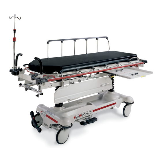
Transport stretcher
Hide thumbs
Also See for Renaissance Series:
- Maintenance manual (123 pages) ,
- Operation manual (19 pages) ,
- Maintenance manual (108 pages)

Related Manuals for Stryker Medical Renaissance Series


Summary of Contents for Stryker Medical Renaissance Series
- Page 1 IMPORTANT File in your maintenance records Renaissance Series 720 Transport Stretcher MAINTENANCE MANUAL For Parts or Technical Assistance 1–800–327–0770...
-
Page 2: Table Of Contents
Table of Contents Introduction Specifications ................Warning / Caution / Note Definition . -
Page 3: Introduction
Introduction INTRODUCTION This manual is designed to assist you with the operation and maintenance of the 720 Transport Stretcher. Read it thoroughly before using the equipment or beginning any maintenance on it. NOTE This manual applies only to 720 stretchers built after 1993, with serial numbers after 94010000. For 720 stretchers built before 1994, use manual part number 720–100–25. -
Page 4: Preventative Maintenance
Preventative Maintenance CHECKLIST (PERFORM A MINIMUM OF TWICE A YEAR) All fasteners secure (reference all assembly prints) Siderails move and latch properly (page 5) Engage brake pedal and push on the stretcher to ensure all casters lock securely (page 10) Steer function working properly All casters secure and swivel properly Body restraints working properly... - Page 5 Cleaning Hand wash all surfaces of the stretcher with warm water and mild detergent. Dry thoroughly. DO NOT STEAM CLEAN, PRESSURE WASH, HOSE OFF OR ULTRASONICALLY CLEAN. Using these methods of cleaning is not recommended and may void this product’s warranty. Clean Velcro AFTER EACH USE.
- Page 6 Notes...
-
Page 7: Service Information
Service Information PNEUMATIC FOWLER ADJUSTMENT Required Tools: 5/32” Hex Allen Wrench 1/2” Open End Wrench Adjustment Procedure: 1. For part identification, refer to page 26.2, drawing 721–231–120. 2. For easier access, move Fowler to 75_ or higher. 3. Using a 1/2” open end wrench, loosen the nuts (item K) in the actuator arms on the end of the trip bar (F). 4. -
Page 8: Siderail Latch Adjustment
Service Information SIDERAIL LATCH ADJUSTMENT Required Tools: 1/8 Hex Allen Wrench WARNING The siderail latch adjustment is pre–set at the factory, and should not normally need adjusting. If adjustment must be done it is important to follow the procedure below. If it is not done properly, injury could occur. Adjustment Procedure: 1. -
Page 9: Pedal Linkage Adjustment
Service Information PEDAL LINKAGE ADJUSTMENT Required Tools: 7/16 Open End Wrench 1/2 Open End Wrench (2) Wooden Blocks (10 – 12 inches in length) Adjustment Procedure: 1. Pump the litter up to full height. 2. Lift the base hood, separating the hood from the base frame. Using the wooden blocks, support the base hood. -
Page 10: Caster Assembly Replacement
Service Information CASTER ASSEMBLY REPLACEMENT Required Tools: 1/8 Roll Pin Punch Drill with 1/8 inch Drill Bit Flat Punch (any size larger than 1/8) Hammer Needle Nose Pliers Floor Jack 3/4 Inch Wrench (2) Wooden Blocks (10 – 12 inches in length) 1 Inch Wrench Torque Wrench (w/ Ft. - Page 11 Service Information CASTER MAINTENANCE Required Tools: 5/8” Wrench 11/16” Wrench Maintenance Procedure: Remove the plastic caster cover (see page 8). Using the 5/8” wrench and the 11/16” wrench, remove the centerlock nut (item A) from the through bolt (item B) for the caster wheel. Support the corner of the stretcher where the wheel is being removed and remove the through bolt (item B) and the molded wheel (item C) .
- Page 12 Notes...
-
Page 13: Caster Cover Installation And Removal
Service Information CASTER COVER INSTALLATION AND REMOVAL Looking through the larger of the two side cut–outs, align cover with axle nut or bolt head, as shown. Double Prongs Push down on the opposite side of the cover until single prong engages with caster horn. Single Prong Top View (Cut–Away) Properly Attached... -
Page 14: Stretcher Height Adjustment
Service Information STRETCHER HEIGHT ADJUSTMENT NOTE The 720 Transport Stretcher is available in three ”fixed” heights: 28”, 30”, and 32”. The pre–set stretcher height was chosen at the time of purchase. Follow the procedure below to change the stretcher height. Refer to page 20 &... -
Page 15: Brake Adjustment
Service Information BRAKE ADJUSTMENT Required Tools: 3/32” Hex Allen Wrench Pry Bar Thread ”Locktite” BASE LUBRICATION 1. Lubricate brake adjuster rod around area shown with MPG–2 grease or equivalent. Do not grease area shown. - Page 16 Notes...
- Page 17 Assembly part number 716–1–251 Note: Parts and assemblies drawn with broken lines are part of optional accessories.
-
Page 18: End Control Base Assembly (With Wheels)
End Control Base Assembly (with Wheels and Brakes) Item Part No. Part Name Qty. 716–1–246 Base Weldment Ass’y 8–17 Soc. Hd. Shoulder Bolt 715–1–158 Caster Nut 715–1–61 Caster Brake Assembly (Page 14) Brake Adjuster Assembly 1210–1–345 Brake/Steer Pedal, Ft. End 1210–1–346 Brake/Steer Pedal, Hd. -
Page 19: Brake Adjuster Assembly
715–1–150 Brake Adjuster Assembly Item Part No. Part Name Qty. 715–1–62 Threaded Stud Assembly 14–4 Nylon Washer 715–1–180 Bearing 28–8 Retaining Ring... -
Page 20: Brake Cam Assembly
715–1–213 Brake Cam Assembly Item Part No. Part Name Qty. 715–1–221 Brake Cam 16–59 Fiberlock Nut 8–21 Soc. Hd. Cap Screw 715–1–173 Brake Connecting Link... - Page 21 716–1–263 End Control Brake Pedal Assembly, Foot Item Part No. Part Name Qty. 716–1–275 Brake Pedal 716–1–262 Brake Rod Ass’y, Ft. End 716–1–269 End Control Brake Pedal Assembly, Head Item Part No. Part Name Qty. 716–1–275 Brake Pedal 716–1–267 Brake Rod Ass’y, Welded NOTE Apply plastic adhesive to the mating surfaces of item A prior to assembly.
-
Page 22: 715-2-21 Caster Assembly With Steerlock
715–2–21 Caster Assembly with Steerlock Item Part No. Part Name Qty. 700–10–50 Steer Lock Caster Weldment 715–2–25 Caster Wheel 16–60 Hex Nut 3–99 Hex Bolt 715–3–96 Hex Bolt 1000–59–10 Latch Assembly 11–310 Flat Washer... -
Page 23: Caster And Caster Cover Replacement Kits
Caster and Caster Cover Replacement Kits Item Part No. Part Name Qty. 715–2–20 Caster Assembly 715–1–266 Caster Cover, Left 715–1–265 Caster Cover, Right P/N 715–259–400 – Kit to replace 4 standard caster assemblies with necessary hardware – no caster covers. P/N 715–269–400 –... - Page 24 Optional Fifth Wheel Base Assembly Item Part No. Part Name Qty. 3–20 Hex Hd. Cap Screw 16–16 Fiberlock Nut 16–49 Nylock Hex Nut 23–25 Hex Washer Hd. Screw 26–8 Roll Pin 81–219 Bearing (page 19) Fifth Wheel Assembly 715–1–136 Fifth Wheel Spring 715–1–149 715–1–157 Fifth Wheel Bearing...
- Page 25 Notes 18.2...
- Page 26 715–1–25 Fifth Wheel Assembly Item Part No. Part Name Qty. 715–1–339 Fifth Wheel Pivot Assembly 715–1–17 Fifth Wheel Bushing 16–11 Flexlock Nut 715–1–15 Spring 715–1–13 Fifth Wheel Bracket 16–12 Flexlock Nut 390–1–54 Wheel 3–31 Hex Head Cap Screw 3–82 Hex Head Cap Screw...
- Page 27 p/n 1001–100–1 (Ref.) HEAD END p/n 716–1–246 (Ref.)
-
Page 28: Stretcher Base Assembly
720–201–50 Stretcher Base Assembly Item Part No. Part Name Qty. 720–33–25 Lower Tower Ass’y 720–201–32 Upper Tower Ass’y 720–201–33 Front Spacer 16–28 Nylock Nut 3–93 Hex Hd. Cap Screw 3–82 Hex Hd. Cap Screw 16–36 Self–Locking Nut 3–85 Hex Hd. Cap Screw 11–3 Washer 13–38... -
Page 29: Base Labeling Assembly
Base Labeling Assembly Item Part No. Part Name Qty. 1001–100–1 Hood Assembly 29–7 Dual Lock (not shown) 29–9 Dual Lock (not shown) 721–31–44 Brake/Steer Label, Head 721–31–45 Brake/Steer Label, Foot 946–1–60 Stryker Logo Label 720–32–90 Specification Label... -
Page 30: Stretcher Graphics
Stretcher Graphics Color Item A Stripe Label Litter Bumper Strip 1001–800–13 1010–700–15 PURPLE 1001–800–23 1010–700–25 GREEN 1001–800–33 1010–700–35 GRAY 1001–800–43 1010–700–45 TEAL 1001–800–53 1010–700–55 PINK 1001–800–63 1010–700–65 BLUE 1001–800–73 1010–700–75 Department Label Part Number Department Label Part Number Emergency 1010–900–1 Endoscopy 1010–900–7 P.A.C.U. - Page 31 720–201–10 Litter Assembly...
-
Page 32: 720-201-10 Litter Assembly
720–201–10 Litter Assembly Item Part No. Part Name Qty. Item Part No. Part Name Qty. 721–201–20 Frame Assembly 1001–34–29 Slider Support Ass’y, Lt. 28–23 Retaining Ring 1001–34–30 Slider Support Ass’y, Rt. 1001–40–12 Foot Board Receptacle 720–201–21 Riser Stop 23–104 Self–Tapping Screw 1001–34–25 End Plug 926–400–142... - Page 33 721–231–10 Pneumatic Fowler Assembly Fowler Frame (Ref.) Fowler Skin (Ref.) Frame Assembly (Ref.) Item Part No. Part Name Qty. 1010–31–78 Gas Spring 14–21 Nylon Flat Washer 16–35 Nylock Hex Nut 4–182 Pivot Bolt 1001–31–30 Yoke Housing 721–231–18 Trip Bar Assembly 15–50 Hex Nut 21–126...
-
Page 34: Pneumatic Fowler Assembly
721–231–110 Pneumatic Fowler to Frame Assembly Item Part No. Part Name Qty. 4–182 Hex Soc. But. Hd. Cap Screw 4–183 Hex Soc. But. Hd. Cap Screw 11–179 Washer 14–21 Washer 15–59 Hex Jam Nut 16–11 Hex Nut 16–35 Hex Nut 23–100 Self–Tapping Screw 25–122... - Page 35 721–231–120 Pneumatic Fowler Assembly Item Part No. Part Name Qty. 4–135 But Hd. Cap Screw 4–161 Hex Soc. But. Hd. Cap Screw 7–34 Truss Hd. Mach. Screw 15–37 Jam Nut 15–50 Hex Nut 16–28 Nylock Nut 21–125 Set Screw 21–126 Set Screw 721–231–12 Fowler Skin...
- Page 36 Outer Housing Assembly, Right and Left Assembly part number 1210–31–106 (Right) Item Part No. Part Name Qty. 25–144 Semi–Tubular Rivet 1210–31–103 Pivot Tab 1210–31–104 Outer Housing, Right Assembly part number 1210–31–107 (Left) Item Part No. Part Name Qty. 25–144 Semi–Tubular Rivet 1210–31–103 Pivot Tab 1210–31–105...
- Page 37 Notes 26.4...
-
Page 38: Manual Fowler Assembly
721–232–10 Manual Fowler Assembly Item Part No. Part Name Qty. 721–232–19 Brace Assembly 14–2 Nylon Flat Washer 3–54 Hex Hd. Cap Screw 16–28 Nylock Hex Nut 3–47 Hex Hd. Cap Screw 1001–32–22 Position Bar Rest 4–135 But. Hd. Cap Screw 16–3 Lock Nut 1001–32–26... - Page 39 721–235–10 Long Transfer System to Frame Assembly HEAD END Item Part No. Part Name Qty. (page 30) Transfer System Ass’y, Rt. (page 29) Transfer System Ass’y, Lt. 10–11 Eye Bolt 38–218 Tension Spring 721–224–25 Spring Retainer, Rt. 3–78 Hex Hd. Cap Screw 11–180 Flat Washer 16–28...
- Page 40 721–234–12 Long Transfer System Assembly, Left Item Part No. Part Name Qty. 721–24–55 Transfer Board Ass’y 721–24–46 Label 721–224–16 Long Pivot, Machined 721–224–33 Connecting Link Ass’y 721–232–17 Pivot Arm Ass’y, Lt. 28–93 Retaining Ring 3–50 Hex Hd. Cap Screw 11–224 Nylon Flat Washer 14–21 Nylon Flat Washer...
- Page 41 721–234–13 Long Transfer System Assembly, Right Item Part No. Part Name Qty. 721–24–55 Transfer Board Ass’y 721–24–46 Label 721–224–16 Long Pivot, Machined 721–224–33 Connecting Link Ass’y, Rt. 721–232–16 Pivot Arm Ass’y, Right 28–93 Retaining Ring 3–50 Hex Hd. Cap Screw 11–224 Nylon Flat Washer 14–21...
- Page 42 721–239–10 Short Transfer System to Frame Ass’y Item Part No. Part Name Qty. (page 33) Transfer System Ass’y, Rt. (page 32) Transfer System Ass’y, Lt. 10–11 Eye Bolt 38–218 Tension Spring 1010–224–25 Spring Retainer 3–78 Hex Hd. Cap Screw 11–180 Flat Washer 16–28 Nylock Hex Nut...
-
Page 43: Short Transfer System Assembly, Left
1010–232–11 Short Transfer System Assembly, Left HEAD END Item Part No. Part Name Qty. 1020–32–100 Transfer Board Ass’y 721–24–46 Label 1010–32–98 Pivot 1010–224–33 Connecting Link Ass’y 1010–232–17 Pivot Arm Ass’y, Lt. 28–93 Retaining Ring 3–50 Hex Hd. Cap Screw 11–224 Nylon Flat Washer 14–21 Nylon Flat Washer... -
Page 44: Short Transfer System Assembly, Right
1010–232–10 Short Transfer System Assembly, Right HEAD END Shaft End (Ref.) Item Part No. Part Name Qty. 1020–32–100 Transfer Board Ass’y 721–24–46 Label 1010–32–98 Pivot 1010–224–33 Connecting Link Ass’y, Rt. 1010–232–16 Pivot Arm Ass’y, Right 28–93 Retaining Ring 3–50 Hex Hd. Cap Screw 11–224 Nylon Flat Washer 14–21... - Page 45 721–26–96 & 721–26–97 Siderail Ass’y, Right & Left (Left Side Shown) Item Part No. Part Name Qty. 1010–26–15 Top Rail 1010–26–34 Upright 1010–26–36 Upright, Bent 1010–26–66 Spacer 25–106 Semi–Tubular Rivet 721–26–84 Round Hole Plug 1010–26–35 Upright, Latch 1010–26–12 Bent Spindle Stop...
- Page 46 721–280 & 721–281 2–Stage I.V. Ass’y, Head & Foot Item Part No. Part Name Qty. (page 36) I.V. Pole Assemby 1001–259–5 I.V. Receptacle Ass’y 16–28 Lock Nut 3–54 Hex Hd. Cap Screw 4–91 But. Hd. Cap Screw 3–50 Hex Hd. Cap Screw 16–20 Self–Locking Nut 1001–59–40...
-
Page 47: 2-Stage I.v. Pole Assembly
1211–110–10 2–Stage I.V. Pole Assembly Item Part No. Part Name Qty. 1001–59–32 Base Tube Assembly 1001–59–31 Extension Tube Assembly 1210–110–47 Lock Ring 1210–110–49 Lock Actuator 14–20 Nylon Flat Washer As Req’d 1010–59–16 I.V. Hook 52–17 Nylon Spacer 926–400–62 Stop Sleeve 1211–110–46 Back–Up Ring 8–31... - Page 48 721–61 & 721–62 3–Stage I.V. Assembly, Head & Foot Item Part No. Part Name Qty. (page 38) I.V. Pole Assembly 1001–259–5 I.V. Receptacle Ass’y 16–28 Lock Nut 3–54 Hex Hd. Cap Screw 4–91 But. Hd. Cap Screw 3–50 Hex Hd. Cap Screw 16–20 Self–Locking Nut...
-
Page 49: 2Nd Stage Assembly
721–61–10 3–Stage I.V. Pole Assembly Item Part No. Part Name Qty. 721–61–24 Base Tube Assembly (page 39) 2nd Stage Assembly (page 40) 3rd Stage Assembly 26–6 Roll Pin 7–4 Truss Hd. Mach. Screw 52–17 Nylon Spacer 1010–59–16 I.V. Hook 14–20 Nylon Flat Washer 1010–61–14 Collar... - Page 50 721–61–25 2nd Stage Assembly Item Part No. Part Name Qty. 721–61–30 2nd Tube Assembly 1210–110–46 Back–Up Ring 1210–110–47 Lock Ring 1210–110–49 Lock Actuator...
-
Page 51: 721-61-20 3Rd Stage Assembly
721–61–20 3rd Stage Assembly Item Part No. Part Name Qty. 38–303 Spring 1010–61–13 Ball Retainer 1010–61–15 Stop Nut 1010–61–16 Retaining Shaft 1010–61–17 Thumb Knob 1010–61–18 Hand Guard 721–31–69 3rd Extension Rod 31–21 Ball... -
Page 52: Tethered I.v. Pole Mounting Assembly
721–287 Tethered I.V. Pole Mounting Assembly Item Part No. Part Name Qty. (page 43) Trough Assembly (page 42) I.V. Pole Assembly 34–22 Cord Clamp 25–79 Pop Rivet 4–85 Soc. Hd. Cap Screw 16–3 Nylock Nut... - Page 53 1001–87–1 Tethered I.V. Pole Assembly Item Part No. Part Name Qty. 721–47–6 I.V. Holder 1001–87–14 Specification Label 1010–22–27 Cable Assembly 741–47–14 Retainer 21–16 Set Screw...
- Page 54 1010–22–25 Tethered I.V. Pole Trough Assembly Item Part No. Part Name Qty. 1010–22–19 I.V. Trough 1010–22–21 Long Bracket Ass’y 1010–22–24 Short Bracket 946–40–110 Lock Clip 37–2 Tube Plug 16–14 Nylock Hex Nut 1–22 Flat Hd. Mach. Screw...
-
Page 55: Tethered I.v. Pole Assembly
721–117 Tethered I.V. Pole Mounting Assembly HEAD END Item Part No. Part Name Qty. 4–66 Soc. Hd. Cap Screw 11–16 Washer 16–3 Fiberlock Nut 25–79 Rivet 34–22 Cable Clamp 1001–59–40 I.V. Plug (page 43.2) Tethered I.V. Pole Assembly 1211–117–21 Backing Plate 1211–117–22 I.V. - Page 56 1211–117–10 Tethered I.V. Pole Assembly Item Part No. Part Name Qty. 4–232 Button Hd. Cap Screw 14–20 Nylon Washer 24–53 Knob 52–17 Spacer 926–400–62 Stop Sleeve 1010–22–27 Cable Assembly 1010–59–16 I.V. Hook 1211–117–11 Extension Rod 1211–117–12 Base Tube Weldment 43.2...
-
Page 57: C-Spine Cassette Holder Assembly
1001–70–1 C–Spine Cassette Holder Assembly Item Part No. Part Name Qty. 1010–70–25 I.V. Adaptor 1010–70–18 Specification Label 11–3 Flat Washer 4–91 But. Hd. Cap Screw (page 45) Support Pole Assembly (page 46) Storage Bracket Ass’y 16–5 Nylock Nut 3–50 Hex Hd. Cap Screw 1001–70–11 Attachment Bracket... -
Page 58: C-Spine Support Pole Assembly
1010–70–10 C–Spine Support Pole Assembly View A–A Item Part No. Part Name Qty. 1010–70–33 Support Tube Cap 26–6 Roll Pin 1010–70–34 Support Arm Weldment 1010–70–42 Cassette Holder Weldment 1010–70–50 Adjustment Tube Weldment 1010–70–30 Base Tube Weldment 1010–70–45 Knob 25–55 Pop Rivet 1010–70–44 Pivot Pin 26–5... -
Page 59: C-Spine Storage Bracket Assembly
1010–70–19 C–Spine Storage Bracket Assembly 6.5” (Ref.) 2” (Ref.) Item Part No. Part Name Qty. 1010–70–20 Storage Bracket Weldment 1010–70–45 Knob 1010–70–23 Storage Label... - Page 60 926–39–10 Defibrillator Tray Assembly Item Part No. Part Name Qty. 946–39–4 Tray 926–39–16 Crosstube 25–55 Rivet 926–39–9 Cover 18–6 Umbrella Nut 7900–1–143 Dual Lock 7900–1–145 Dual Lock 946–39–3 Support Tube 926–1–82 Label 390–57–12 Long Strap 390–57–13 Short Strap 946–1–283 Label 926–39–15 Holder 2–44...
-
Page 61: Foot Board/Chartholder Assembly
926–40–10 Foot Board/Chartholder Assembly Item Part No. Part Name Qty. 946–28–11 Chart Holder 946–29–6 Foot Board 1020–30 Optional Upright Oxygen Bottle Holder Ass’y Item Part No. Part Name Qty. 1020–30–11 Upright Bottle Holder 27–12 Cotter Pin 1020–30–17 Specification Label... -
Page 62: Replacement Parts
Replacement Parts and Kits PART NAME PART NUMBER Ankle Restraint Straps ..........946–43 Body Restraint Straps . -
Page 63: Warranty
Warranty Limited Warranty: Stryker Medical Division, a division of Stryker Corporation, warrants to the original purchaser that its products should be free from defects in material and workmanship for a period of one (1) year after date of delivery. Stryker’s obligation under this warranty is expressly limited to supplying replacement parts and labor for, or replacing, at its option, any product which is, in the sole discretion of Stryker, found to be defective. -
Page 64: Return Authorization
Warranty Return Authorization: Merchandise cannot be returned without approval from the Stryker Customer Service Department. An autho- rization number will be provided which must be printed on the returned merchandise. Stryker reserves the right to charge shipping and restocking fees on returned items. SPECIAL, MODIFIED, OR DISCONTINUED ITEMS NOT SUBJECT TO RETURN. - Page 65 6300 Sprinkle Road, Kalamazoo, MI 49001–9799 (800) 327–0770 DH 10/97 720–90–25 REV D...
Need help?
Do you have a question about the Renaissance Series and is the answer not in the manual?
Questions and answers