
Subscribe to Our Youtube Channel
Related Manuals for Stryker Medical 1009


Summary of Contents for Stryker Medical 1009
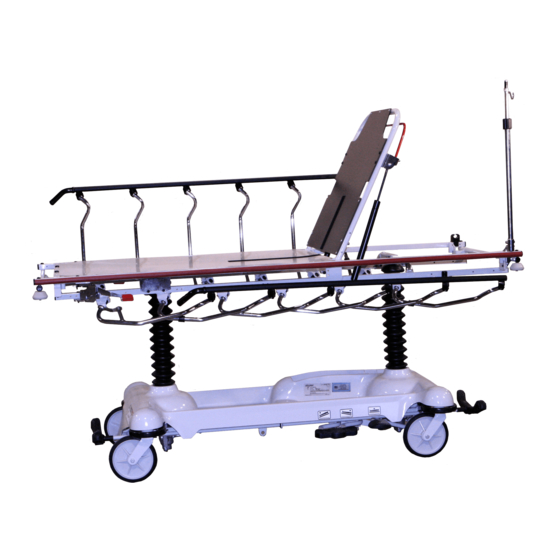
- Page 1 Advantage Series 1009 Emergency Care Stretcher 1509 PACU Stretcher Maintenance Manual For Parts or Technical Assistance 800–327–0770...
-
Page 2: Table Of Contents
Table of Contents Introduction Specifications ................Warning / Caution / Note Definition . - Page 3 Table of Contents Assembly Drawings and Parts Lists (Continued) Base Assembly with Fifth Wheel Option ........... Pivot Rod Assembly .
-
Page 4: Introduction
Introduction INTRODUCTION This manual is designed to assist you with the maintenance of the 1009 Emergency Care Stretcher and the 1509 PACU Bed. Read it thoroughly before using the equipment or beginning any maintenance on it. SPECIFICATIONS 1009 1509 Maximum Weight Capacity... -
Page 5: Preventative Maintenance
Preventative maintenance should be performed at a minimum of annually. A preventative maintenance pro- gram should be established for all Stryker Medical equipment. Preventative maintenance may need to be performed more frequently based on the usage level of the product. -
Page 6: Cleaning
Cleaning Hand wash all surfaces of the stretcher with warm water and mild detergent. Dry thoroughly. DO NOT STEAM CLEAN, PRESSURE WASH, HOSE OFF OR ULTRASONICALLY CLEAN. Using these methods of cleaning is not recommended and may void this product’s warranty. Clean Velcro AFTER EACH USE. -
Page 7: Service Information
Service Information CASTER ASSEMBLY REPLACEMENT 1. Remove the old caster assembly. 2. Install the replacement caster and caster nut. Tighten the caster nut to 90–105 ft.–lb. with a torque wrench. NOTE A new caster assembly with a 3M patch does not require the application of Loctite at assembly. However, the patch is appropriate for only one installation. -
Page 8: Caster Cover Installation And Removal
Service Information CASTER COVER INSTALLATION AND REMOVAL Looking through the larger of the two side cut–outs, align cover with axle nut or bolt head, as shown. Double Prongs Push down on the opposite side of the cover until single prong engages with caster horn. Single Prong Top View (Cut–Away) Properly Attached... -
Page 9: Brake Cam Replacement
Service Information BRAKE CAM REPLACEMENT Brake Cam Part Number 715–201–213 Required Tools: Phillips Screwdriver String or Bungee Cord 3/32” Allen Wrench 1/8” Allen Wrench Procedure: 1. Remove the four Phillips screws holding the base hood to the frame. Lift and support the base hood using string or bungee cord. -
Page 10: Brake Adjustment
Service Information BRAKE ADJUSTMENT Required Tools: 3/32” Hex Allen Wrench Pry Bar Thread ”Locktite” Flat on thread of stud must always be aligned with the set screw. Turn must always be full circle only. BASE SIDE CONTROL PEDAL LINKAGE ADJUSTMENT Required Tools: 3/8”... -
Page 11: Base Side Control Brake/Steer Gear Replacement
Service Information BASE SIDE CONTROL BRAKE/STEER GEAR REPLACEMENT Required Tools: Pliers String or Bungee Cord Floor Jack or Equivalent 1/8” Allen Wrench 5/32” Allen Wrench 3/8” Box End Wrench (2) 9/16” Box End Wrenches 3/16” Punch 1/4” Punch Hammer Procedure: 1. -
Page 12: Jack Replacement
Service Information JACK REPLACEMENT (WITHOUT COMPRESSION SPRING) Required Tools: 3/8” Wrench 1/2” Socket 1/2” Wrench Needle–Nosed Pliers Replacement Procedure: 1. Apply stretcher brakes. Raise litter to full up. Raise Fowler to full up and raise siderails. 2. Use a 3/8” wrench to remove the bolt in the litter support tube above black bellows on both ends. 3. -
Page 13: Jack Torque Specifications
Service Information JACK ASSEMBLY TORQUE SPECIFICATION Jack Assembly with Threads Oiled 1. Jack Cap Assembly to Jack Actuator Cylinder 75 to 85 Foot Pounds 2. Jack Actuator Cylinder to Jack Base Assembly 55 to 65 Foot Pounds Jack Base Assembly with Threads Oiled 1. -
Page 14: Checking Hydraulic Fluid Level
Service Information CHECKING HYDRAULIC FLUID LEVEL Required Tools: 3/8 Open End Wrench 3/4 Open End Wrench Procedure: WARNING To avoid personal injury or damage to the stretcher, remove the litter and the base hood before beginning service on the jacks. 1. -
Page 15: Adjustable P.c. Valve Replacement
Service Information CONSTANT FLOW JACK DESCENT RATE ADJUSTMENT Required Tools: Bungee Cords Adjustment Procedure: 1. Pump the litter up to full height 2. Lift the base hood, separating the Velcro holding it to the base frame. 3. The adjustable descent valve is located on the base of the jack and has a blue knob on the end. To adjust, loosen the silver locking ring by turning it counterclockwise. - Page 16 Service Information ADJUSTABLE PRESSURE COMPENSATED (P.C.) VALVE REPLACEMENT (CONTINUED) 8. Install the replacement P.C. valve. Moisten the O–ring seal with hydraulic fluid to ensure a tight seal. 9. Tighten the valve manually and then an additional 1/8–1/4 turn with a 13/16” wrench. Do not over –tight- en or damage may occur to the O–ring seal.
-
Page 17: Hydraulic Check Valve Replacement
Service Information HYDRAULIC CHECK VALVE REPLACEMENT Required Tools: 3/8 Open End Wrench Stiff Wire (with bent, pointed end) Small Needle Nose Pliers 3/4 Open End Wrench Torque Wrench (with Ft. Lbs. adjust.) 7/32 Hex Allen Wrench Replacement of Check Valve WARNING To avoid personal injury or damage to the stretcher, remove the litter and the base hood before beginning service on the jacks. -
Page 18: Hydraulic Check Valve Replacement
Service Information HYDRAULIC CHECK VALVE REPLACEMENT (CONTINUED) Replacement of Release Valve WARNING To avoid personal injury or damage to the stretcher, remove the litter and the base hood before beginning service on the jacks. Lower the jack rod completely to relieve the pressure on the pump piston side of the jack. -
Page 19: Base Lubrication
Service Information BASE LUBRICATION... -
Page 20: Big Wheel/Bearing Replacement
Service Information BIG WHEEL/BEARING REPLACEMENT Required Tools: 15/16” Wrench or Socket & Ratchet (2) Bungee Cords Torque Wrench Small Standard Screwdriver Procedure: 1.Apply the stretcher brakes. 2.Pump the litter up to full height. 3.Lift the base hood and support it from the litter frame using bungee cords. 4.Using a small standard screwdriver, remove the big wheel hub cap, being careful not to damage the outer surface of the hub cap (see page 45 for part reference). -
Page 21: Big Wheel Return Spring Adjustment
Service Information BIG WHEEL RETURN SPRING ADJUSTMENT Required Tools: 1/2” Deep Well Socket & Ratchet (2) Bungee Cords Procedure: 1. Apply the stretcher brakes. 2. Pump the litter up to full height. 3. Lift the base hood and support it from the litter frame using bungee cords. 4. -
Page 22: Pneumatic Fowler Adjustment
Service Information PNEUMATIC FOWLER ADJUSTMENT Required Tools: 5/32” Hex Allen Wrench 1/2” Open End Wrench Adjustment Procedure: 1. For easier access, move Fowler to 75_ or higher. 2. Using a 1/2” open end wrench, loosen the nuts in the actuator arms on the end of the trip bar. 3. -
Page 23: Replacement Parts
........1009/1509–159 Hydraulic Jack, Constant Descent . -
Page 24: Side Control Base Assembly
Side Control Base Assembly... - Page 25 Side Control Base Assembly...
- Page 26 Side Control Base Assembly Assembly part number 1210–1–210 (reference only) FOOT END HEAD END...
- Page 27 Side Control Base Assembly Item Part No. Part Name Qty. Item Part No. Part Name Qty. 715–1–11 Brake Cushion 3–47 Hex Hd. Cap Screw 715–1–61 Caster Brake Weldment 3–62 Hex Hd. Cap Screw 715–1–92 Pump Pedal Shaft 3–85 Hex Hd. Cap Screw 715–201–94 Compression Spring 4–146...
-
Page 28: End Control Base Assembly
End Control Base Assembly... - Page 29 End Control Base Assembly...
- Page 30 End Control Base Assembly...
-
Page 31: End Control Base Assembly
End Control Base Assembly Item Part No. Part Name Qty. Item Part No. Part Name Qty. 715–1–11 Brake Cushion 1210–201–155 Foot Rel. Pedal, Offset, Lt 715–1–61 Caster Brake Weldment 1210–201–201 Pivot Pin Bracket, Foot End 1 715–201–94 Compression Spring 1210–201–251 Insert 715–1–133 Collar 3–3... -
Page 32: 715-201-150 Brake Adjuster Assembly
715–201–150 Brake Adjuster Assembly Item Part No. Part Name Qty. 715–1–180 Cam Bearing 715–201–62 Threaded Stud Assembly 14–4 Nylon Washer 28–8 External Retaining Ring... -
Page 33: 715-201-213 Brake Cam Assembly
715–201–213 Brake Cam Assembly Item Part No. Part Name Qty. 16–59 Hex Nut 8–21 Soc. Hd. Shoulder Screw 715–201–173 Brake Connecting Link 715–301–221 Brake Cam... -
Page 34: Side Control Pump Pedal Assembly
Side Control Pump Pedal Assembly Item Part No. Part Name Qty. 81–44 Bronze Bearing 715–201–126 Slip–On Pedal Pad 715–201–83 Pump Pedal Weldment 26–143 Groove Pin... -
Page 35: End Control Pump Pedal Assembly
716–201–288 Foot End Pump Pedal Assembly Item Part No. Part Name Qty. 26–145 Spring Pin 716–201–14 Foot End Pump Rod 716–1–283 Pump Pivot Housing 715–201–126 Pedal 1210–201–551 Eye Bolt 16–14 Nylock Nut 26–261 Groove Pin... - Page 36 716–201–292 Head End Pump Pedal Assembly Item Part No. Part Name Qty. 26–145 Spring Pin 716–1–285 Pump Pivot Housing, Hd. End 716–201–14 Head End Pump Rod 715–201–126 Pedal 1210–201–551 Eye Bolt 16–14 Nylock Nut 26–261 Groove Pin...
-
Page 37: Base Assembly With Steerlock Caster Option
Base Assembly w/Steerlock Caster Option Assembly part number 1000–159 (reference only) Item Part No. Part Name Qty. (page 37) Steer Caster Assembly (page 38) Caster Assembly 1000–210–62 Steer Lock Linkage Bar 8–21 Shoulder Bolt 14–2 Washer 38–211 Spring... -
Page 38: Caster Assembly
715–269–100 Caster Assembly w/Steerlock Assembly part number 715–2–21 (reference only) Item Part No. Part Name Qty. 700–10–50 Steer Lock Caster Weldment 715–2–25 Caster Wheel 16–60 Hex Nut 3–99 Hex Bolt 715–3–96 Hex Bolt 1000–59–10 Latch Assembly 11–310 Flat Washer... - Page 39 Standard Caster Assembly Item Part No. Part Name Qty. 3–99 Hex Hd. Cap Screw 11–310 Washer 16–60 Hex Nut 715–2–16 Horn Assembly 715–3–96 Hex Hd. Cap Screw 715–1–265 Wheel Cover, Right 715–1–266 Wheel Cover, Left 715–2–25 Wheel 715–1–158 Caster Nut (not shown) p/n 715–259–400 –...
-
Page 40: Base Assembly With Fifth Wheel Option
Base Assembly w/Fifth Wheel Option Assembly part number 1010–260 (reference only) Item Part No. Part Name Qty. 14–79 Nylon Washer 11–13 Washer 27–16 Cotter Pin (page 40) Pivot Rod Assembly 1210–1–145 1210–1–148 Torsion Spring 1210–201–149 Spring Spacer 4–10 Bolt (page 41) Wheel Arm Assembly 1210–1–146 Torsion Spring... -
Page 41: Pivot Rod Assembly
Pivot Rod Assembly Assembly part number 1210–201–2 (reference only) Item Part No. Part Name Qty. 1210–1–143 Pivot Rod 14–79 Nylon Washer 1210–1–144 Roller 28–131 Snap Ring 27–16 Cotter Pin... -
Page 42: 715-201-125 Wheel Arm Assembly
715–201–125 Wheel Arm Assembly Item Part No. Part Name Qty. 1210–201–553 Wheel Arm 1210–1–147 Fifth Wheel 3–31 Hex Hd. Cap Screw 16–35 Nylock Nut... -
Page 43: Big Wheel Base Assembly
Optional Side Control Big Wheel Base Assembly... -
Page 44: Big Wheel Base Assembly
Optional Side Control Big Wheel Base Assembly FOOT END HEAD END... - Page 45 Optional Side Control Big Wheel Base Assembly FOOT END HEAD END...
- Page 46 Optional Side Control Big Wheel Base Assembly...
- Page 47 Optional Side Control Big Wheel Base Assembly Item Part No. Part Name Qty. Item Part No. Part Name Qty. 42–20 Collar 1210–301–653 Wheel Cover Assembly 715–1–11 Brake Cushion 11–3 Washer 715–1–61 Caster Brake Weldment 11–4 Washer 715–1–92 Pump Pedal Shaft 11–224 Washer 715–1–94...
- Page 48 Optional End Control Big Wheel Base Assembly Assembly part number 1210–102–210 (reference only)
- Page 49 Optional End Control Big Wheel Base Assembly...
- Page 50 Optional End Control Big Wheel Base Assembly...
- Page 51 Optional End Control Big Wheel Base Assembly...
- Page 52 Optional End Control Big Wheel Base Assembly Item Part No. Part Name Qty. Item Part No. Part Name Qty. 42–20 Collar 1210–301–200 Hd. End Pin Brkt. Pivot 715–1–11 Brake Cushion 1210–301–201 Ft. End Pin Brkt. Pivot 715–1–61 Caster Brake Weldment 11–3 Washer 715–1–92...
- Page 53 Optional Big Wheel Interface Assembly Assembly part number 1210–201–450 (reference only) Item Part No. Part Name Qty. 81–303 Flange Bushing 1210–201–412 Roller Pin 1210–201–625 Interface Sleeve 1210–201–445 Interface Weldment (page 53) Roller Assembly 3–32 Hex Hd. Cap Screw 3–345 Hex Hd. Cap Screw 10–4 Eye Bolt 11–410...
- Page 54 1210–301–641 Optional Big Wheel Roller Assembly Item Part No. Part Name Qty. 1210–301–640 Roller 28–184 Snap Ring 81–299 Bearing...
- Page 55 1210–301–619 Optional Big Wheel Assembly Item Part No. Part Name Qty. 81–226 Bearing 1210–201–625 Wheel Inner Sleeve...
- Page 56 1210–301–900 Optional Big Wheel Cam Assembly Item Part No. Part Name Qty. 715–1–333 Release Valve Stop Sleeve 1210–201–610 Connecting Link 1210–201–671 Dampener 1210–301–901 28–184 Snap Ring 4–328 Soc. Hd. Cap Screw 81–299 Needle Bearing...
- Page 57 1231–70–10 Variable Descent Jack Assembly Item Part No. Part Name Qty. Item Part No. Part Name Qty. 388–100–38 Plug 715–1–325 Actuator Rod 390–1–238 Actuator Gasket (page 57) Jack Base Ass’y 390–1–243 Gasket 926–20–161 Parker Packing 390–1–244 Base Gasket 926–20–162 Wear Ring 390–2–139 Retaining Ring 4–14...
-
Page 58: Jack Assembly
Jack Base Assembly Assembly part number 1231–70–5 (reference only) Item Part No. Part Name Qty. Item Part No. Part Name Qty. 48–147 Base Plug 926–20–153 Check Valve 390–2–134 Conical Comp. Spring 926–20–154 Seal 715–1–307 Needle Valve 1210–170–13 Base Plug 715–1–309 Valve Plug 1210–270–12 Jack Base 715–1–329... - Page 59 1231–70–210 Constant Flow Jack Assembly Item Part No. Part Name Qty. Item Part No. Part Name Qty. 388–100–38 Plug 926–20–161 Parker Packing 390–1–238 Actuator Gasket 926–20–162 Wear Ring 390–1–243 Gasket (page 59) Jack Base Ass’y 390–1–244 Base Gasket 4–14 Soc. Hd. Cap Screw 390–2–139 Retaining Ring 45–14...
- Page 60 Constant Flow Jack Base Assembly Assembly part number 5050–370–100 (reference only) Item Part No. Part Name Qty. Item Part No, Part Name Qty. 38–311 Compression Spring 715–1–341 Poppet 45–6 O–Ring 715–270–1 45–966 O–Ring 926–20–153 Check Valve 45–967 O–Ring 926–20–154 Seal 390–2–134 Conical Comp.
- Page 61 715–100–425 Jack Pump Piston Assembly Assembly part number 715–201–325 (reference only) Item Part No. Part Name Qty. 715–1–328 Piston Wear Ring 715–1–400 O–Ring Back Up 715–200–316 Pump Cylinder 715–201–318 Pump Piston 715–201–327 Cylinder Wear Ring 14–50 Bearing Retainer 45–110 O–Ring 715–1–329 Pump Seal (not shown)
- Page 62 Notes...
-
Page 63: Base Assembly With Side Control Brakes
Optional Side Control Brake Assembly... - Page 64 Optional Side Control Brake Assembly Item Part No. Part Name Qty. 1210–301–400 Gear Box Weldment 1210–301–412 Support 1210–201–409 Side Control Brake/Steer Rod 1210–201–407 1210–301–406 Spacer 1210–301–405 Miter/Spur Gear 1210–301–404 Spur Gear 1210–301–403 Miter Gear 1210–201–401 Flange Bearing 1210–201–336 Steer Label 1210–201–335 Brake Label 1210–201–153...
-
Page 65: Base Assembly With Uni-Lower Pedal
Optional Uni–Lower Pedal Assembly Assembly part number 1210–500 (reference only) Item Part No. Part Name Qty. 715–201–127 Uni–Lowering Pedal 715–1–333 Release Rod Stop Sleeve 25–50 Pop Rivet... -
Page 66: Base Assembly With Dual Lowering Pedals
Optional Dual Lowering Pedal Assembly Assembly part number 1210–501 (reference only) Item Part No. Part Name Qty. 715–201–126 Pump Pedal 26–143 Groove Pin... -
Page 67: Base Labeling Assembly
Side Control Base Labeling Assembly HEAD END See page 68 for Department Label part numbers Item Part No. Part Name Qty. 1001–200–1 Base Hood 715–1–134 Bellows 1210–201–335 Red Brake Label 1210–201–336 Green Steer Label 946–201–60 Stryker Logo Label Color Item A Control Item B Control Item C Control Item D Control... -
Page 68: Base Labeling Assembly
End Control Base Labeling Assembly HEAD END See page 68 for Department Label part numbers Item Part No. Part Name Qty. 1001–200–1 Hood 715–1–134 Bellows 1210–201–335 Brake Label 1210–201–336 Steer Label 1210–201–337 Head Down Label, Foot End 1210–201–338 Foot Down Label, Foot End 1210–201–339 Head Down Label, Head End 1210–201–340... - Page 69 Department Labels BASE HOOD DEPARTMENT LABELS Department Label Part Number Emergency 1010–900–215 PACU 1010–900–220 Transport 1010–900–225 Surgery 1010–900–230 Extended Stay 1010–900–235 Maternity 1010–900–240 Endoscopy 1010–900–245 Radiology 1010–900–250 Nuclear Medicine 1010–900–255 Ambulatory Surgery 1010–900–260 G.I. Lab 1010–900–265 Cath. Lab 1010–900–270 Same Day Surgery 1010–900–275 Cardio.
- Page 70 Optional Big Wheel Side Control Base Labeling Ass’y HEAD END See page 68 for Department Label part numbers Color Item A Control Item B Control Item C Control Item D Control Litter Bumper Set P/N Label, Head End Label, Foot End Label, Right Label, Left Strip...
- Page 71 Optional Big Wheel End Control Base Labeling Ass’y See page 68 for Department Label part numbers HEAD END Color Item A Control Item B Control Item C Side Control Litter Bumper Strip Set P/N Label, Head End Label, Foot End Label 1210–800–117 1210–850–115...
-
Page 72: Litter Assembly
1009 Litter Assembly Assembly part number 1009–30–10 (reference only) HEAD END Item Part No. Part Name Qty. Item Part No. Part Name Qty. 11–360 Plastic Spacer 1001–1–37 Jack Supt. Tube, Hd. 3–359 Hex Hd. Cap Screw 1001–201–30 Trend. Support 4–330 Soc. - Page 73 Hole Plug 3–359 Hex Hd. Cap Screw 1001–201–30 Trend Support 4–330 Soc. Hd. Cap Screw 1001–40–12 Foot Board Receptacle 16–118 Hex Nut 1009–30–44 Bumper Channel 16–117 Hex Nut 1001–201–29 Carrier Tube 25–40 Pop Rivet 1501–201–32 Support Tube 28–72 Retaining Ring 1210–800–8...
-
Page 74: Siderail To Litter Assembly, Fold To Head
Siderail to Litter Assembly, Fold–to Head Assembly part number 1009–20–10 (reference only) HEAD END Item Part No. Part Name Qty. 4–135 But. Hd, Cap Screw 4–136 But. Hd. Cap Screw 11–77 Flat Washer 16–118 Nylock Nut 21–105 Set Screw 37–74 Hole Plug 38–220... -
Page 75: Siderail Assembly, Fold To Head
Siderail Assembly, Right & Left, Fold to Head Assembly part numbers 1010–26–17 (Right) 1010–26–19 (Left) (reference only) (LEFT SIDERAIL IS SHOWN) Item Part No. Part Name Qty. 1010–26–15 Top Rail 1010–26–83 Upright 1010–26–84 Upright, Bent 1010–26–82 Sleeve Bearing 25–106 Semi–Tubular Rivet 1010–26–10 Round Hole Plug 1010–26–85... -
Page 76: Siderail To Litter Assembly, Fold To Foot
Siderail to Litter Assembly, Fold to Foot Assembly part number 1009–21–10 (reference only) HEAD END Item Part No. Part Name Qty. 4–135 But. Hd, Cap Screw 4–136 But. Hd. Cap Screw 11–77 Flat Washer 16–118 Nylock Nut 21–105 Set Screw 37–74... -
Page 77: Siderail Assembly, Fold To Foot
Siderail Assembly, Right & Left, Fold to Foot Assembly part numbers 721–26–96 (Right) 721–26–97 (Left) (reference only) (Right Side Shown) Item Part No. Part Name Qty. 1010–26–15 Top Rail 1010–26–83 Upright 1010–26–84 Upright, Bent 1010–26–82 Spacer 25–106 Semi–Tubular Rivet 1010–26–10 Round Hole Plug 1010–26–85 Upright, Latch... -
Page 78: Pneumatic Fowler Assembly
1009 Pneumatic Fowler to Frame Assembly Assembly part number 1210–31–10 (reference only) HEAD END Item Part No. Part Name Qty. 4–182 But. Hd. Cap Screw 4–104 But. Hd. Cap Screw 11–179 Nylon Washer 14–21 Nylon Washer 16–116 Nylock Hex Nut 16–117... - Page 79 1009 Pneumatic Fowler Assembly (Fiberresin) Assembly part number 1210–31–120 (reference only) Item Part No. Part Name Qty. 4–161 Hex Soc. But. Hd. Cap Screw 7–20 Truss Hd. Mach. Screw 25–124 Pop Rivet 15–37 Jam Nut 15–50 Hex Nut 16–28 Nylock Nut 21–125...
- Page 80 1509 Pneumatic Fowler to Frame Assembly Assembly part number 1710–31–10 (reference only) HEAD END Item Part No. Part Name Qty. 4–182 But. Hd. Cap Screw 4–104 But. Hd. Cap Screw 11–179 Nylon Washer 14–21 Nylon Washer 16–116 Nylock Hex Nut 16–117 Nylock Hex Nut 23–256...
- Page 81 1509 Pneumatic Fowler Assembly (Fiberresin) Assembly part number 1710–31–120 (reference only) Item Part No. Part Name Qty. 4–161 But. Hd. Cap Screw 7–20 Truss Hd. Mach. Screw 25–124 Pop Rivet 15–37 Jam Nut 15–50 Hex Nut 16–28 Fiberlock Nut 21–125 Set Screw 21–126 Set Screw...
- Page 82 Outer Housing Assembly, Right and Left Assembly part number 1210–31–106 (Right) Item Part No. Part Name Qty. 25–144 Semi–Tubular Rivet 1210–31–103 Pivot Tab 1210–31–104 Outer Housing, Right Assembly part number 1210–31–107 (Left) Item Part No. Part Name Qty. 25–144 Semi–Tubular Rivet 1210–31–103 Pivot Tab 1210–31–105...
-
Page 83: Crank Fowler Assembly
1009 Crank Fowler Assembly (Fiberresin) Assembly part number 1210–33–10 (reference only) Item Part No. Part Name Qty. Item Part No. Part Name Qty. 4–97 Hex But. Hd. Cap Screw 25–133 Pop Rivet 4–104 But. Hd. Cap Screw 946–1–64 Fowler Operation Label 7–70... -
Page 84: Crank Fowler Assembly
1509 Crank Fowler Assembly (Fiberresin) Assembly part number 1710–33–10 (reference only) Item Part No. Part Name Qty. Item Part No. Part Name Qty. 4–97 Hex But. Hd. Cap Screw 25–133 Pop Rivet 4–104 But. Hd. Cap Screw 946–1–64 Fowler Operation Label 7–70 Truss Hd. -
Page 85: Fowler Crankscrew Assembly
1001–33–25 (1009) Fowler Crankscrew Ass’y 1501–33–25 (1509) Fowler Crankscrew Ass’y Item Part No. Part Name Qty. 1001–33–26 Drive Bar Assembly 1501–33–26 Drive Bar Assembly 1550–1–16 Crank Assembly 946–33–18 Crank Disc 938–1–177 Knob 16–102 Kep Nut 378–124–29 Shoulder Bolt 946–33–35 Fowler Screw 26–14... -
Page 86: Stationary Foot End Assembly
1009 Stationary Foot End Assembly (Steel) Assembly part number 1010–232–20 (reference only) Frame Assembly (Ref.) HEAD END Item Part No. Part Name Qty. 1010–232–21 Footsection Skin (Steel) 381–24–7 Velcro Pile 25–79 Pop Rivet... - Page 87 1009 Stationary Foot End Assembly (Fiberresin) Assembly part number 1010–332–20 (reference only) Frame Assembly (Ref.) HEAD END Item Part No. Part Name Qty. 1010–332–21 Footsection Skin (Fiberresin) 381–24–7 Velcro Pile 25–133 Pop Rivet...
- Page 88 1509 Stationary Foot End Assembly (Steel) Assembly part number 1510–232–20 (reference only) HEAD END Item Part No. Part Name Qty. 1510–232–21 Footsection Skin 381–24–7 Velcro Pile 24 1/2” 25–79 Pop Rivet...
-
Page 89: Stationary Foot End Assembly
1509 Stationary Foot End Assembly (Fiberresin) Assembly part number 1510–332–20 (reference only) Frame Assembly (Ref.) Item Part No. Part Name Qty. 1510–332–21 Footsection Skin (Fiberresin) 381–24–7 Velcro Pile 25–133 Pop Rivet... -
Page 90: Knee Gatch Assembly
1009 Knee Gatch Assembly (Steel) Assembly part number 1010–634–10 (reference only) 1010–201–20 Litter Frame Item Part No. Part Name Qty. Item Part No. Part Name Qty. 3–355 Hex Hd. Cap Screw 1001–34–131 Slider Support 3–358 Hex Hd. Cap Screw 1010–234–15 Mounting Bracket 4–327... -
Page 91: Knee Gatch Assembly
1509 Knee Gatch Assembly (Steel) Assembly part number 1510–634–10 (reference only) 1510–201–20 Litter Frame Item Part No. Part Name Qty. Item Part No. Part Name Qty. 3–47 Hex Hd. Cap Screw (page 91) Gatch Crankscrew Ass’y 1 3–76 Hex Hd. Cap Screw 1211–234–24 Thigh Support, Left 4–105 Soc. -
Page 92: Knee Gatch Crankscrew Assembly
1001–134–19 Knee Gatch Crankscrew Assembly Item Part No. Part Name Qty. 378–124–29 Shoulder Bolt 938–1–175 Bearing Assembly 938–1–177 Knob 946–33–18 Crank Disk 1001–134–47 Knee Gatch Screw 1510–34–55 Gatch Drive Tube Assembly 1510–34–84 Screw Cover Assembly 1550–1–14 Magnet 1550–1–16 Crank Assembly 16–118 Nylock Nut 26–14... -
Page 93: Four Corner Option Assembly
1009–153 Four Corner Option Assembly HEAD END Item Part No. Part Name Qty. 4–156 But. Hd. Cap Screw 16–6 Kep Nut 1009–30–36 Corner Cover... -
Page 94: Head End Push Bar Option Assembly
1009–155 Head End Push Bar Option Assembly 1509–155 Head End Push Bar Option Assembly HEAD END Item Part No. Part Name Qty. 3–355 Hex Hd. Cap Screw 3–356 Hex Hd. Cap Screw 16–118 Nylock Nut 1010–254–4 P.U.P. Receptacle Wldmt., Lt. -
Page 95: Head End Push Handles Assembly
1009–151 Head End Push Handles/Fold–to–Hd. Siderails HEAD END Item Part No. Part Name Qty. 3–355 Hex Hd. Cap Screw 3–356 Hex Hd. Cap Screw 3–357 Hex Hd. Cap Screw 16–118 Hex Nut 26–114 Spring Pin 1010–254–4 Receptacle, Left 1010–254–6 Receptacle, Right... - Page 96 1009–152 Head End Push Handles/Fold–To–Ft. Siderails HEAD END Item Part No. Part Name Qty. 3–355 Hex Hd. Cap Screw 3–356 Hex Hd. Cap Screw 3–357 Hex Hd. Cap Screw 16–118 Hex Nut 26–114 Spring Pin 1010–254–4 Receptacle, Left 1010–254–6 Receptacle, Right...
-
Page 97: Push Handle Assembly
1211–351–10 Push Handle Assembly Item Part No. Part Name Qty. 1010–354–24 Stop Link 1211–151–18 Sleeve Assembly 26–118 Roll Pin... -
Page 98: Removable I.v. Pole Assembly
390–25 Standard, Removable I.V. Pole Assembly Item Part No. Part Name Qty. 24–23 Plastic Knob 390–3–53 Double I.V. Ass’y 393–3–43 Tube Assembly 4–496 Soc. Hd. Cap Screw... - Page 99 1009–117 & 1509–117 Optional Tethered I.V. Assembly Item Part No. Part Name Qty. 4–107 Soc. Hd. Cap Screw 4–156 Hex Soc. But. Hd. Cap Screw 11–62 Washer 16–3 Fiberlock Nut 16–6 Kep Nut 25–179 Closed End Rivet 34–22 Cord Clamp 1001–59–12...
- Page 100 1211–117–10 Tethered I.V. Pole Assembly Item Part No. Part Name Qty. 52–17 Spacer 1211–117–20 Cable Assembly 926–400–62 Stop Sleeve 1010–59–16 I.V. Hook 1211–117–11 Extension Rod 1211–117–12 Base Tube Weldment 4–495 Low Hd. Soc. Hd. Cap Screw 1211–117–16 Knob 14–20 Nylon Washer 4–232 Button Hd.
-
Page 101: 2-Stage I.v. Pole Mounting Assembly
2–Stage I.V. Pole Mounting Assembly, Head End Assembly part numbers 1009–110 & 1509–110 FOOT END Item Part No. Part Name Qty. 3–356 Hex Hd. Cap Screw 4–66 Soc. Hd. Cap Screw 4–452 But. Hd. Cap Screw 4–156 Hex Soc. But. Hd. Cap Screw 11–62... -
Page 102: Pole Latch Assembly
2–Stage I.V. Pole Mounting Assembly, Foot End Assembly part numbers 1009–112 & 1509–112 HEAD END Item Part No. Part Name Qty. 3–356 Hex Hd. Cap Screw 4–66 Soc. Hd. Cap Screw 4–452 But. Hd. Cap Screw 4–156 Hex Soc. But. Hd. Cap Screw 11–62... - Page 103 1211–210–10 Optional 2–Stage I.V. Pole Assembly Item Part No. Part Name Qty. 8–31 Soc. Hd. Cap Screw 52–17 Washer 926–400–162 Spacer 1211–210–29 2nd Stage Assembly 1001–359–13 Dampener 1001–159–28 Base Tube 1010–259–16 I.V. Hook (page 101) I.V. Pole Latch 1001–359–112 Pivot...
-
Page 104: I.v. Pole Latch Assembly
1211–210–26 Optional I.V. Pole Latch Assembly Item Part No. Part Name Qty. 28–167 Retaining Ring 31–4 Steel Ball 38–392 Crest–to–Crest Spring 1211–91–34 Release Label 1211–110–18 I.V. Latch Seal 1211–110–20 Washer 1211–110–21 I.V. Latch Locking Pin 1211–110–22 I.V. Latch Guide 1211–110–24 I.V. -
Page 105: 3-Stage I.v. Pole Mounting Assembly
3–Stage I.V. Pole Mounting Assembly, Head End Assembly part numbers 1009–111 & 1509–111 FOOT END Item Part No. Part Name Qty. 3–356 Hex Hd. Cap Screw 4–66 Soc. Hd. Cap Screw 4–452 But. Hd. Cap Screw 4–156 Hex Soc. But. Hd. Cap Screw 11–62... -
Page 106: 3Rd Stage Assembly
3–Stage I.V. Pole Mounting Assembly, Foot End Assembly part numbers 1009–113 & 1509–113 HEAD END Item Part No. Part Name Qty. 3–356 Hex Hd. Cap Screw 4–65 Soc. Hd. Cap Screw 4–452 But. Hd. Cap Screw 4–156 Hex Soc. But. Hd. Cap Screw 11–62... -
Page 107: Upright Oxygen Bottle Holder Assembly
1211–211–10 Optional 3–Stage I.V. Pole Assembly Item Part No. Part Name Qty. 7–4 Truss Hd. Machine Screw 26–76 Roll Pin 52–17 Spacer 1211–210–31 2nd Stage Assembly 926–400–162 Spacer (page 105) 3rd Stage Assembly 1001–161–23 Base Tube 1010–259–16 I.V. Hook 1010–61–14 Collar (page 101) I.V. -
Page 108: Foot Extension/ Defibrillator Tray Assembly
1211–110–32 Optional 3rd Stage Assembly NOTE Item F, part number 1010–61–18 is left hand thread. When removing it, turn clockwise to loosen it. Item Part No. Part Name Qty. 31–21 Ball 38–303 Compression Spring 1010–61–13 Ball Retainer 1010–61–16 Retaining Shaft 1010–61–17 Thumb Knob 1010–61–18... -
Page 109: 926-40-100 Foot Board/Chartholder Assembly
926–40–100 Foot Board/Chartholder Assembly Assembly part number 926–40–10 (reference only) Item Part No. Part Name Qty. 946–28–11 Chart Holder 946–29–6 Foot Board 1020–30 Upright Oxygen Bottle Holder Assembly Item Part No. Part Name Qty. 1020–30–11 Upright Bottle Holder 27–12 Cotter Pin 1020–30–17 Specification Label... -
Page 110: Fowler X-Ray Cassette Mounting Assembly
1010–50–100 Foot Extension/Defibrillator Tray Ass’y Assembly part number 1010–50–210 (reference only) Label Detail Label Detail Item Part No. Part Name Qty. Item Part No. Part Name Qty. 8–49 Socket Hd. Shoulder Bolt 1010–50–50 Knob 14–20 Nylon Washer 1010–50–57 “Max. Weight” Label 14–21 Nylon Washer 1010–50–205... -
Page 111: Fowler X-Ray Cassette Assembly
926–39 Optional Defibrillator Tray Assembly Assembly part number 926–39–10 (reference only) Umbrella Nut/Crosstube Detail Strap Securing Detail Item Part No. Part Name Qty. Item Part No. Part Name Qty. 946–39–4 Tray 946–39–3 Support Tube 926–39–16 Crosstube 926–1–82 Label 25–55 Rivet 1010–50–21 Long Strap 926–39–9... -
Page 112: Heel Stirrup And Support Assembly
1001–23 Fowler X–Ray Cassette Mounting Assembly Item Part No. Part Name Qty. (page 110) X–Ray Cassette Ass’y 16–121 Self–Locking Nut 4–456 Button Hd. Cap Screw 1001–23–13 Tray Latch 1020–23–13 Tray Hinge, Right 1020–23–12 Tray Hinge, Left 25–86 Pop Rivet... -
Page 113: Right Stirrup Support Assembly
1001–23–10 Fowler X–Ray Cassette Assembly Item Part No. Part Name Qty. 1001–23–12 Tray 1020–23–16 Post Housing 1001–23–14 Actuating Rod 926–23–64 Post 1010–23–37 Rod Guide 1020–23–21 Knob 1010–23–28 Tray Angle 926–23–70 Block Assembly 926–23–69 Washer 14–3 Washer 38–122 Compression Spring 1020–23–26 Spacer 1020–23–19 Tray Hinge, Right... -
Page 114: Left Stirrup Support Assembly
1001–55 Heel Stirrup and Support Assembly Assembly part number 1001–55–10 (reference only) FOOT END Item Part No. Part Name Qty. 3–358 Hex Hd. Cap Screw 11–159 Flat Washer 16–118 Nylock Hex Nut (page 112) Stirrup Support Ass’y, Rt. (page 113) Stirrup Support Ass’y, Lt. -
Page 115: Heel Stirrup Assembly
1001–55–15 Right Stirrup Support Assembly Item Part No. Part Name Qty. 650–2–32 Lock Screw Assembly 966–51–19 Wedge Lock, Modified 1001–55–11 Mounting Bracket 1010–55–16 Right Support Tube Wldmt. 4–494 Soc. Hd. Cap Screw 11–410 Washer 1211–117–16 Knob 26–7 Roll Pin 38–171 Compression Spring... -
Page 116: C-Spine Cassette Holder Assembly
1001–55–16 Left Stirrup Support Assembly Item Part No. Part Name Qty. 650–2–32 Lock Screw Assembly 966–51–19 Wedge Lock, Modified 1001–55–11 Mounting Bracket 1010–55–26 Left Support Tube Ass’y 4–494 Soc. Hd. Cap Screw 11–410 Washer 1211–117–16 Knob 26–7 Roll Pin 38–171 Compression Spring... - Page 117 Heel Stirrup Assembly Assembly part number 1010–55–29 (reference only) Item Part No. Part Name Qty. 390–20–13 Stirrup 390–20–9 Stirrup Holder Assembly 1010–55–30 Extension Tube Assembly 24–11 Knob 26–43 Roll Pin 22–8 Drive Screw...
-
Page 118: C-Spine Storage Bracket Assembly
1001–70 C–Spine Cassette Holder Assembly Item Part No. Part Name Qty. 1010–70–25 I.V. Adaptor 1010–70–18 Specification Label 11–447 Flat Washer 4–54 But. Hd. Cap Screw (page 116) Support Pole Assembly (page 117) Storage Bracket Ass’y 16–118 Nylock Nut 3–356 Hex Hd. Cap Screw 1001–70–11 Attachment Bracket 3–355... -
Page 119: C-Spine Support Pole Assembly
C–Spine Support Pole Assembly Assembly part number 1010–70–10 (reference only) View A–A Item Part No. Part Name Qty. 1010–70–33 Support Tube Cap 26–6 Roll Pin 1010–70–34 Support Arm Weldment 1010–70–42 Cassette Holder Weldment 1010–70–50 Adjustment Tube Weldment 1010–70–30 Base Tube Weldment 1010–70–45 Knob 25–55... - Page 120 C–Spine Storage Bracket Assembly Assembly part number 1010–70–19 (reference only) 6.5” (Ref.) 2” (Ref.) Item Part No. Part Name Qty. 1010–70–20 Storage Bracket Weldment 1010–70–45 Knob 1010–70–23 Storage Label...
-
Page 121: Obtaining Parts And Service
Mattresses and Siderail Pads Mattress, 3” Thick x 26” Wide, Enhanced Comfort ....part # 1001–48–106 Mattress, 4” Thick x 26” Wide, Enhanced Comfort . -
Page 122: Freight Damage Claims
Echo Mattresses Mattress, 26” Wide ..........part # 1059–459–10 Mattress, 29”... -
Page 123: Warranty
No employee or representative of Stryker is authorized to change this warranty in any way. Stryker Medical stretchers are designed for a 10 year expected life under normal use conditions and appropri- ate periodic maintenance as described in the maintenance manual for each device. -
Page 124: Return Authorization
Claims for any short shipment must be made within thirty (30) days of invoice. International Warranty Clause: This warranty reflects U.S. domestic policy. Warranty outside the U.S. may vary by country. Please contact your local Stryker Medical representative for additional information. - Page 125 European Representative Stryker France Phone: 33148632290 BP 50040–95946 Roissy Ch. de Gaulle Fax: 33148632175 Cedex–France 6300 Sprinkle Road, Kalamazoo, MI 49001–9799 (800) 327–0770 www.strykermedical.com DH 4/02 1009–90–203 REV E...
Need help?
Do you have a question about the 1009 and is the answer not in the manual?
Questions and answers