Table of Contents
Advertisement
Quick Links
Advertisement
Table of Contents

Related Manuals for Supermicro H13SRD-F


Summary of Contents for Supermicro H13SRD-F
- Page 1 H13SRD-F USER’S MANUAL Revision 1.0...
- Page 2 State of California, USA. The State of California, County of Santa Clara shall be the exclusive venue for the resolution of any such disputes. Supermicro's total liability for all claims will not exceed the price paid for the hardware product.
- Page 3 It provides information for the installation and use of the H13SRD-F motherboard. About This Motherboard The H13SRD-F motherboard supports an AMD Ryzen™ 7000 processor with up to 170W TDP in an AM5 socket. The motherboard supports up to 128GB ECC and Non-ECC DDR5 UDIMM memory with speeds of up to 5200 MT/s in two DIMM slots or 3600 MT/s in four DIMM slots.
- Page 4 Super H13SRD-F User's Manual Contacting Supermicro Headquarters Address: Super Micro Computer, Inc. 980 Rock Ave. San Jose, CA 95131 U.S.A. Tel: +1 (408) 503-8000 Fax: +1 (408) 503-8008 Email: Marketing@supermicro.com (General Information) Sales-USA@supermicro.com (Sales Inquiries) Government_Sales-USA@supermicro.com (Gov. Sales Inquiries) Support@supermicro.com (Technical Support) RMA@supermicro.com...
-
Page 5: Table Of Contents
Preface Table of Contents Chapter 1 Introduction 1.1 Checklist ..........................8 H13SRD-F Quick Reference .....................11 Quick Reference Table ......................12 Motherboard Features .......................13 1.2 Processor and Chipset Overview ..................16 1.3 Special Features ........................16 Recovery from AC Power Loss ..................16 1.4 System Health Monitoring ....................17 Onboard Voltage Monitors ....................17... - Page 6 Super H13SRD-F User's Manual DIMM Installation ......................32 DIMM Removal .........................32 2.5 Rear Panel I/O Ports ......................33 2.6 Connectors & Headers .......................36 Power Connections ......................36 Headers ..........................37 2.7 Jumper Settings .........................41 How Jumpers Work ......................41 2.8 LED Indicators ........................46 Chapter 3 Troubleshooting 3.1 Troubleshooting Procedures ....................47...
- Page 7 Preface Appendix A BIOS Codes A.1 BIOS POST Codes ......................89 Appendix B Software B.1 Microsoft Windows OS Installation ...................112 B.2 Driver Installation ......................114 B.3 SuperDoctor 5 .........................115 ® Appendix C Standardized Warning Statements Appendix D UEFI BIOS Recovery D.1 Overview ...........................119 D.2 Recovering the UEFI BIOS Image ...................119 D.3 Recovering the BIOS Block with a USB Device ..............120...
-
Page 8: Chapter 1 Introduction
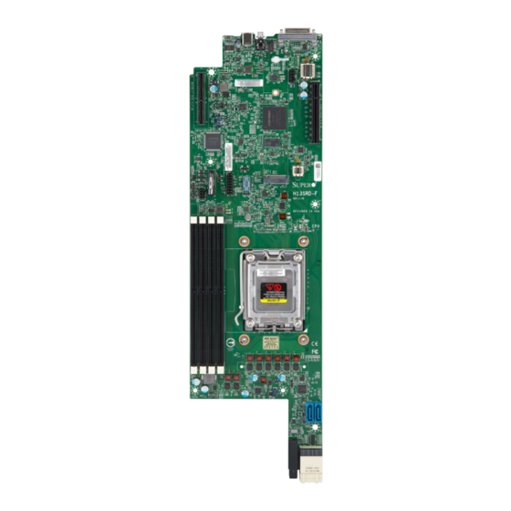
A secure data deletion tool designed to fully erase all data from storage devices can be found at our website: https://www.supermicro.com/about/policies/disclaimer.cfm?url=/wdl/ utility/Lot9_Secure_Data_Deletion_Utility/ • If you have any questions, contact our support team at: support@supermicro.com This manual may be periodically updated without notice. Check the Supermicro website for possible updates to the manual revision level. - Page 9 Chapter 1: Introduction Figure 1-1. H13SRD-F Motherboard Image Note: All graphics shown in this manual were based upon the latest PCB revision available at the time of publication of the manual. The motherboard you received may or may not look exactly the same as the graphics shown in this manual.
- Page 10 Super H13SRD-F User's Manual Figure 1-2. H13SRD-F Motherboard Layout (not drawn to scale) JKVM1 USB2 (3.2 Gen2) SRW2 JTPM1 MAC CODE SRW1 LEDM1 JVRM1 JWD1 JPO1 JBM1 CPLD JPT1 JMD1 H13SRD-F M.2-C PCIe 5.0 x2 REV:1.00 SGPIO1 DESIGNED IN USA...
-
Page 11: H13Srd-F Quick Reference
Chapter 1: Introduction H13SRD-F Quick Reference JUIDB1 JKVM1 LED2 USB2 LED1 JKVM1 USB2 (3.2 Gen2) SRW2 SRW2 JTPM1 JTPM1 J9 MICRO-LP PCIe 4.0 x8 Slot MAC CODE SRW1 SRW1 JVRM1 LEDM1 LEDM1 JVRM1 JWD1 J10 SLOT1 PCIe 5.0 x8 JPO1... -
Page 12: Quick Reference Table
Super H13SRD-F User's Manual Quick Reference Table Jumper Description Default Setting JSS1 AOC SAS Enable/Disable Pins 1-2: Disabled JBM1 Disable IPMI Share LAN Pins 1-2 Open: Enabled JPO1 CPU Throttle when PWR_FAIL Pins 2-3: Disabled JPT1 Onboard TPM 2.0 Enable/Disable... -
Page 13: Motherboard Features
• System on Chip DIMM Size • 8GB, 16GB, or 32GB at 1.1V Note: For the latest processor/memory updates, refer to our website at http://www.supermicro.com/products/moth- erboard. Expansion Slots • One PCIe 5.0 x8 Open-End Slot with 75W power • One Micro-LP Slot PCIe 5.0 x8 with two USB 2.0 connections •... - Page 14 Super H13SRD-F User's Manual Motherboard Features BIOS • 256Mb AMI BIOS® SPI Flash BIOS • ACPI 6.4, Plug and Play (PnP), BIOS rescue hot-key, and SMBIOS 3.5 or later Power Management • ACPI power management (supports S5) • Power button override mechanism •...
- Page 15 Chapter 1: Introduction Figure 1-5. System Block Diagram SVI3 Vender: MPS AMD Ryzen 7000X DDR5 (CHA) UDIMM-A1 UDIMM-A2 up to 5200MT/s PCIe 5.0 x8 (L0 - L7) PCIe x8 SLOT(open end) DDR5 (CHB) UDIMM-B1 2x HDD PORTS UDIMM-B2 NVMe up to 5200MT/s 1x USB Type-C 2x USB 3.2 (P0) AOC-SAS...
-
Page 16: Processor And Chipset Overview
Super H13SRD-F User's Manual 1.2 Processor and Chipset Overview Built upon the functionality and capability of the AMD Ryzen™ 7000, the H13SRD-F motherboard provides system performance, power efficiency, and feature sets to address the needs of next-generation computer users, and dramatically increases system performance for a multitude of server applications. -
Page 17: System Health Monitoring
Chapter 1: Introduction 1.4 System Health Monitoring Onboard Voltage Monitors The onboard voltage monitor will continuously scan crucial voltage levels. Once a voltage becomes unstable, a warning is given, or an error message is sent to the screen. The user can adjust the voltage thresholds to define the sensitivity of the voltage monitor. -
Page 18: Acpi Features
Super H13SRD-F User's Manual 1.5 ACPI Features The Advanced Configuration and Power Interface (ACPI) specification defines a flexible and abstract hardware interface that provides a standard way to integrate power management features throughout a computer system, including its hardware, operating system and application software. -
Page 19: Chapter 2 Installation
Chapter 2: Installation Chapter 2 Installation 2.1 Static-Sensitive Devices Electrostatic Discharge (ESD) can damage electronic com ponents. To avoid damaging your system board, it is important to handle it very carefully. The following measures are generally sufficient to protect your equipment from ESD. Precautions •... -
Page 20: Processor And Heatsink Installation
Thermal grease is pre-applied on a new heatsink. No additional thermal grease is needed. • Refer to the Supermicro website for updates on processor support. • All graphics in this manual are for illustrative purposes only. Your components may look different. -
Page 21: Overview Of The Processor Socket
Chapter 2: Installation Overview of the Processor Socket The processor socket is protected by an outer plastic protective cover. If the motherboard is new, the socket will also be protected by an inner plastic cover. 1. Outer Plastic Cover 2. Inner Plastic Cover 3. -
Page 22: Overview Of The Heatsink
Super H13SRD-F User's Manual Overview of the Heatsink The heatsink is attached to the socket with Phillips #1 screws after the processor is secured. If this is a new heatsink, thermal grease is pre-applied. -
Page 23: Installing The Processor
Chapter 2: Installation Installing the Processor Note: Do not remove the plastic cover covering the outside of the socket. This cover will pop out during installation of the processor. 1. Use a finger to push down the lever, then move the lever rightward. Pull the lever until it passes over the processor socket. - Page 24 Super H13SRD-F User's Manual 3. Pick up the processor on its left and right edges. Hold the processor over the socket and align the arrow on the top-left corner of the processor with the arrow on the top-left corner of the socket. Gently lower it onto the AM5 socket pins.
- Page 25 Chapter 2: Installation 5. Reattach the lever arm onto the right side of the socket. The outer plastic cover will pop out when the lever arm is reattached. Note: Store the outer plastic cover. Attach the outer plastic cover to the socket force frame when storing or transporting the motherboard without a processor.
-
Page 26: Installing The Heatsink
Super H13SRD-F User's Manual Installing the Heatsink 1. After the processor is secure, you must install the heatsink to the socket frame. Ensure a proper amount of thermal grease is applied to the heatsink. Lower the heatsink down until the four screws on the heatsink align with the four screw holes on the socket frame. - Page 27 Chapter 2: Installation 2. Starting with two screws on opposite corners, use a Phillips #1 screwdriver to press down and tighten the screws on the heatsink. 3. When finished, the heatsink will be secured over the socket and processor.
-
Page 28: Motherboard Installation
Super H13SRD-F User's Manual 2.3 Motherboard Installation All motherboards have standard mounting holes to fit different types of chassis. Make sure that the locations of all the mounting holes for both the motherboard and the chassis match. Although a chassis may have both plastic and metal mounting fasteners, metal ones are highly recommended because they ground the motherboard to the chassis. -
Page 29: Installing The Motherboard
Chapter 2: Installation Installing the Motherboard 1. Install the I/O shield into the back of the chassis, if applicable. 2. Locate the mounting holes on the motherboard. See the previous page for the location. 3. Locate the matching mounting holes on the chassis. Align the mounting holes on the motherboard against the mounting holes on the chassis. -
Page 30: Memory Support And Installation
Memory Support The H13SRD-F supports up to 128GB of ECC and Non-ECC DDR5 UDIMM memory with speeds of up to 5200 MT/s in two DIMM slots or 3600 MT/s in four DIMM slots. Refer to the table below for DIMM support information. -
Page 31: General Guidelines For Optimizing Memory Performance
DIMM module necessary for board operation. JKVM1 USB2 (3.2 Gen2) SRW2 JTPM1 MAC CODE SRW1 LEDM1 JVRM1 JWD1 JPO1 JBM1 CPLD JPT1 JMD1 H13SRD-F M.2-C PCIe 5.0 x2 REV:1.00 SGPIO1 DESIGNED IN USA JBT1 DIMMA1 DIMMA2 DIMMB1 DIMMB2 BIOS LICENSE JSS1 SAS1 SAS2 JPWR1... -
Page 32: Dimm Installation
Super H13SRD-F User's Manual DIMM Installation JKVM1 USB2 1. Insert DIMM modules in the following (3.2 Gen2) order: DIMMA2, DIMMA1, then DIMMB2, SRW2 JTPM1 DIMMB1, and insert the desired number MAC CODE SRW1 of DIMMs into memory slots based on the... -
Page 33: Rear Panel I/O Ports
(3.2 Gen2) SRW2 JTPM1 MAC CODE SRW1 LEDM1 JVRM1 JPO1 JWD1 JBM1 CPLD JPT1 JMD1 H13SRD-F M.2-C PCIe 5.0 x2 REV:1.00 SGPIO1 DESIGNED IN USA JBT1 BIOS LICENSE JSS1 SAS1 SAS2 JPWR1 PRESS FIT Figure 2-1. Rear Panel I/O Port Locations and Definitions... - Page 34 Super H13SRD-F User's Manual KVM Connector The Keyboard, Video, and Mouse (KVM) connector at JKVM1 supports a set of keyboard, monitor, and mouse to control multiple computers. It also provides two USB 2.0 connections (USB0/1), one serial connection (COM1), and a VGA connection (VGA).
- Page 35 SRW2 JTPM1 MAC CODE SRW1 LEDM1 JVRM1 JPO1 JWD1 JBM1 CPLD JPT1 JMD1 H13SRD-F M.2-C PCIe 5.0 x2 REV:1.00 SGPIO1 DESIGNED IN USA JBT1 1. Power Switch, Power LED 2. UID Switch 3. UID LED (LED2) BIOS LICENSE JSS1 SAS1...
-
Page 36: Connectors & Headers
Super H13SRD-F User's Manual 2.6 Connectors & Headers Power Connections Power Connector JPWR1 is the 12V input power connector for the backplane power connector. JKVM1 USB2 (3.2 Gen2) SRW2 JTPM1 MAC CODE SRW1 JVRM1 LEDM1 JPO1 JWD1 JBM1 CPLD JPT1... -
Page 37: Headers
Port 80 connection. Use this header to enhance system performance and data security. Refer to the table below for pin definitions. Go to the following link for more information on the TPM: http://www.supermicro.com/manuals/other/TPM.pdf. Trusted Platform Module Header Pin Definitions... - Page 38 Super H13SRD-F User's Manual Serial Link General Purpose I/O Header There is one Serial Link General Purpose Input/Output (S-SGPIO) header located on the motherboard. Refer to the table below for pin definitions. S-SGPIO Header Pin Definitions Pin# Definition Pin# Definition...
- Page 39 Micro Low-Profile PCIe 5.0 x8 Slot with two USB 2.0 connections There is one Micro-LP PCIe 5.0 x8 slot with two USB 2.0 connections at J9. This slot is used for a Supermicro Micro-LP Network card. PCIe 5.0 x8 Slot (Open-End support up to 75W) There is one PCIe 5.0 x8 Open-End Slot with 75W power at J10.
- Page 40 Super H13SRD-F User's Manual MicroCloud Backplane Connector There is one MicroCloud Backplane Connector for 2x PCIe 5.0 x4 / Dedicated IPMI LAN / 2x AOC SATA/SAS at J12. JKVM1 USB2 (3.2 Gen2) SRW2 JTPM1 MAC CODE SRW1 LEDM1 JVRM1 JPO1...
-
Page 41: Jumper Settings
Chapter 2: Installation 2.7 Jumper Settings How Jumpers Work To modify the operation of the motherboard, jumpers can be used to choose between optional settings. Jumpers create shorts between two pins to change the function of the connector. Pin 1 is identified with a square solder pad on the printed circuit board. See the diagram below for an example of jumping pins 1 and 2. - Page 42 Super H13SRD-F User's Manual CMOS Clear JBT1 is used to clear CMOS, which will also clear any passwords. Instead of pins, this jumper consists of contact pads to prevent accidentally clearing the contents of CMOS. To Clear CMOS 1. First power down the system and unplug the power cord(s).
- Page 43 (3.2 Gen2) SRW2 JTPM1 MAC CODE SRW1 LEDM1 JVRM1 JPO1 JWD1 JBM1 CPLD JPT1 JMD1 H13SRD-F M.2-C PCIe 5.0 x2 REV:1.00 SGPIO1 DESIGNED IN USA JBT1 1. AOC SAS Enable/Disable 2. IPMI Shared LAN BIOS LICENSE JSS1 SAS1 SAS2 JPWR1...
- Page 44 Super H13SRD-F User's Manual Onboard TPM 2.0 Enable/Disable Use JPT1 to enable or disable support for the onboard TPM 2.0 module. The default setting is Enabled. TPM 2.0 Enable/Disable Jumper Settings Jumper Setting Definition Pins 1-2 Enabled (Default) Pins 2-3...
- Page 45 USB2 (3.2 Gen2) SRW2 JTPM1 MAC CODE SRW1 LEDM1 JVRM1 JPO1 JWD1 JBM1 CPLD JPT1 JMD1 H13SRD-F M.2-C PCIe 5.0 x2 REV:1.00 SGPIO1 DESIGNED IN USA JBT1 1. CPU Throttle when PWR_Fail BIOS LICENSE JSS1 SAS1 SAS2 JPWR1 PRESS FIT...
-
Page 46: Led Indicators
Super H13SRD-F User's Manual 2.8 LED Indicators OH/Power/Fan Fail LED LED1 is the OH/Power/Fan Fail LED. OH/Power/Fan Fail LED LED Color Definition Blinking Red Power Fail or FAN Fail Solid Red Overheat BMC Heartbeat LED LEDM1 is the BMC Heartbeat LED. When the LED is blinking green, the BMC is working. -
Page 47: Chapter 3 Troubleshooting
Chapter 3: Troubleshooting Chapter 3 Troubleshooting 3.1 Troubleshooting Procedures Use the following procedures to troubleshoot your system. If you have followed all of the procedures below and still need assistance, refer to the ‘Technical Support Procedures’ and/ or ‘Returning Merchandise for Service’ section(s) in this chapter. Always disconnect the AC power cord before adding, changing or installing any non hot-swap hardware components. -
Page 48: No Video
Super H13SRD-F User's Manual No Video 1. If the power is on but you have no video, remove all add-on cards and cables. 2. Use the speaker to determine if any beep codes are present. Refer to Appendix A for details on beep codes. -
Page 49: Losing The System's Setup Configuration
Chapter 3: Troubleshooting 5. Make sure that all memory modules are fully seated in their slots. Follow the instructions given in Section 2-4 in Chapter 2. 6. Follow the instructions given in the DIMM population tables listed in Section 2-4 to install your memory modules. - Page 50 Super H13SRD-F User's Manual B. If the system becomes unstable before or during OS installation, check the following: 1. Source of installation: Make sure that the devices used for installation are working properly, including boot devices such as USB flash drive or media drives.
-
Page 51: Technical Support Procedures
Before contacting Technical Support, take the following steps. Also, note that as a motherboard manufacturer, Supermicro also sells motherboards through its channels, so it is best to first check with your distributor or reseller for troubleshooting services. They should know of any possible problems with the specific system configuration that was sold to you. -
Page 52: Frequently Asked Questions
Note: The SPI BIOS chip used on this motherboard cannot be removed. Send your motherboard back to our RMA Department at Supermicro for repair. For BIOS Recov- ery instructions, refer to the AMI BIOS Recovery Instructions posted at http://www. -
Page 53: Battery Removal And Installation
Chapter 3: Troubleshooting 3.4 Battery Removal and Installation Battery Removal To remove the onboard battery, follow the steps below: 1. Power off your system and unplug your power cable. 2. Locate the onboard battery as shown below. 3. Using a tool such as a pen or a small screwdriver, push the battery lock outwards to unlock it. -
Page 54: Returning Merchandise For Service
Super H13SRD-F User's Manual 3.5 Returning Merchandise for Service A receipt or copy of your invoice marked with the date of purchase is required before any warranty service will be rendered. You can obtain service by calling your vendor for a Returned Merchandise Authorization (RMA) number. -
Page 55: Chapter 4 Uefi Bios
Chapter 4: UEFI BIOS Chapter 4 UEFI BIOS 4.1 Introduction This chapter describes the AMIBIOS™ Setup utility for the motherboard. The BIOS is stored on a chip and can be easily upgraded using a flash program. Note: Due to periodic changes to the BIOS, some settings may have been added or deleted and might not yet be recorded in this manual. -
Page 56: Main Setup
Super H13SRD-F User's Manual 4.2 Main Setup When you first enter the AMI BIOS setup utility, you enter the Main setup screen. You can always return to the Main setup screen by selecting the Main tab on the top of the screen. - Page 57 Chapter 4: UEFI BIOS Memory Information Total Memory This feature displays the total size of memory available in the system.
-
Page 58: Advanced Setup Configurations
Super H13SRD-F User's Manual 4.3 Advanced Setup Configurations Use the arrow keys to select the Advanced submenu and press <Enter> to access the submenu items. Warning: Take caution when changing the Advanced settings. An incorrect value, an improper DRAM frequency, or a wrong BIOS timing setting may cause the system to malfunction. When this occurs, revert the setting to the manufacture default settings. - Page 59 Chapter 4: UEFI BIOS Bootup NumLock State Use this feature to set the Power-on state for the <Numlock> key. The options are On and Off. Wait For "F1" If Error Select Enabled to force the system to wait until the <F1> key is pressed if an error occurs. The options are Disabled and Enabled.
- Page 60 Super H13SRD-F User's Manual CPU Configuration Module Version: This feature displays the Module Version. PSS Support Use this feature to enable or disable the generation of ACPI_PCC, _PSS, and _PCT objects. The options are Disabled and Enabled. PPC Adjustment (Available when PSS Support is set to "Enabled") Use this feature to adjust _PPC, the PState object.
- Page 61 Chapter 4: UEFI BIOS --------- Cache per core --------- • L1 Instruction Cache: • L1 Data Cache: • L2 Cache: • Total L3 Cache per Socket: North Bridge Configuration Above 4G MMIO Limit Use this feature to set the Above 4G MMIO Limit between 38 to 43 bits. This feature works only when "Above 4G Decoding is enabled"...
- Page 62 Super H13SRD-F User's Manual SHA256 PCR Bank (Available when "Security Device Support" is set to Enable) Select Enabled to enable SHA256 PCR Bank support to enhance system integrity and data security. The options are Enabled and Disabled. SHA384 PCR Bank (Available when "Security Device Support" is set to Enable) Select Enabled to enable SHA384 PCR Bank support to enhance system integrity and data security.
- Page 63 Chapter 4: UEFI BIOS Device Select When this feature is set to Auto, TPM 1.2 devices will be enumerated if TPM 2.0 are not detected. The options are TPM 2.0 and Auto. AMD fTPM configuration AMD fTPM switch Use this feature to setup AMD fTPM. The options are AMD CPU fTPM, AMD CPU HSP, and Route to SPI TPM.
- Page 64 Super H13SRD-F User's Manual Serial Port 2 Configuration Serial Port 2 Select Enabled to enable SOL (COM). The options are Disabled and Enabled. Device Settings (Available when "SOL" is set to Enabled) This feature displays the base I/O port address and the Interrupt Request address of serial port 1.
- Page 65 Chapter 4: UEFI BIOS Bits Per Second Use this feature to set the transmission speed for a serial port used in Console Redirection. Make sure that the same speed is used in the host computer and the client computer. A lower transmission speed may be required for long and busy lines.
- Page 66 Super H13SRD-F User's Manual Putty KeyPad This feature selects Function Keys and KeyPad settings for Putty, which is a terminal emulator designed for the Windows OS. The options are VT100, LINUX, XTERMR6, SCO, ESCN, and VT400. Legacy Console Redirection Settings...
- Page 67 Chapter 4: UEFI BIOS Terminal Type EMS Use this feature to select the target terminal emulation type for Console Redirection. Select VT100 to use the ASCII character set. Select VT100Plus to add color and function key support. Select ANSI to use the extended ASCII character set. Select VT-UTF8 to use UTF8 encoding to map Unicode characters into one or more bytes.
- Page 68 Super H13SRD-F User's Manual Re-Size BAR Support When this feature is set to Enabled, resizable Base Address Register (BAR) will be available for PCIe devices that support this feature. The options are Disabled and Enabled. SR-IOV Support Select Enabled for Single-Root IO Virtualization support. The options are Disabled and Enabled.
- Page 69 Chapter 4: UEFI BIOS USB Configuration The following information is displayed: • USB Devices XHCI Hand-off This is a work-around solution for operating systems that do not support Extensible Host Controller Interface (XHCI) hand-off. The XHCI ownership change should be claimed by the XHCI driver.
- Page 70 Super H13SRD-F User's Manual Media Detect Count Use this feature to select the wait time (in seconds) for the BIOS ROM to detect the presence of a LAN media either via the Internet connection or via a LAN port. Press <+> or <-> on your keyboard to change the value.
- Page 71 Chapter 4: UEFI BIOS MAC:XX:XX:XX:XX:XX:XX-IPv6 Network Configuration MAC:XX:XX:XX:XX:XX:XX-IPv6 Network Configuration Enter Configuration Menu The following information is displayed: • Interface Name • Interface Type • MAC address • Host addresses • Route Table • Gateway addresses • DNS addresses Interface ID Use this feature to change/enter the 64 bit alternative interface ID for the device.
- Page 72 Super H13SRD-F User's Manual Discard Changes and Exit Press <Enter> to discard changes and exit. Save Changes and Exit Press <Enter> to save changes and exit. The options are Yes and No. HTTP Boot Configuration HTTP Boot Policy Use this feature to set the HTTP boot policy. The options are Apply to all LANs, Apply to each LAN, and Boot Priority #1 instantly.
- Page 73 Use this feature to enter the second Supermicro KMS server IPv4 address in dotted-decimal notation. Supermicro KMS TCP Port number Use this feature to enter the Supermicro KMS TCP port number. The valid range is 100 - 9999. The default setting is 5696. KMS Time Out Use this feature to enter the KMS server connecting time-out (in seconds).
- Page 74 Super H13SRD-F User's Manual Client Private Key For the client private key, use this feature to enroll factory defaults or load the KMS TLS certificates from the file. The options are Update, Delete, and Export. SATA Mode Selection SATA 1 and 2 Storage RAID Support The options are Disabled, RAID 0, and RAID 1.
- Page 75 Chapter 4: UEFI BIOS Blink LEDs Use this feature to identify the physical network port by blinking the associated LED. The default setting is 0 (up to 15 seconds). The following information is displayed: • UEFI Driver • Adapter PBA •...
- Page 76 Super H13SRD-F User's Manual Discard Changes and Exit Use this feature to discard all changes and exit TLS settings. Delete Certification This feature is used to delete the certificate if it has been enrolled in the system. The options are Disabled and Enabled.
-
Page 77: Bmc
Chapter 4: UEFI BIOS 4.4 BMC Use this feature to configure Baseboard Management Console (BMC) settings. BMC Firmware Revision This feature indicates the IPMI firmware revision used in your system. BMC STATUS This feature indicates the status of the IPMI firmware installed in your system. System Event Log Enabling/Disabling Options SEL Components... - Page 78 Super H13SRD-F User's Manual When SEL is Full This feature allows you to determine what the BIOS should do when the system event log is full. Select Erase Immediately to erase all events in the log when the system event log is full.
- Page 79 Chapter 4: UEFI BIOS Station MAC Address (Available when "Configuration Address Source" is set to Static) This feature displays the Station MAC address for this computer. Mac addresses are six two-digit hexadecimal numbers. Gateway IP Address (Available when "Configuration Address Source" is set to Static) This feature displays the Gateway IP address for this computer.
- Page 80 Super H13SRD-F User's Manual Advanced Settings (Available when "Configuration Address Source" is set to DHCPv6 Stateless) Use this feature to select if the Domain Name System (DNS) server IP address should be found automatically. The options are Auto obtain DNS server IP and Manually obtain DNS server IP.
-
Page 81: Security
BIOS Setup utility. The options are Setup and Always. Supermicro Security Erase Configuration This section displays the following information if a storage device is detected by the system: •... - Page 82 Super H13SRD-F User's Manual Security Function Select Password to set an HDD/SATA password, which will allow you to configure the security settings of the HDD/SATA device. Select Security Erase-Password to enter a SATA user password to erase the password and the contents previously stored in the HDD/ SATA device.
- Page 83 Chapter 4: UEFI BIOS Reset to Setup Mode This feature deletes all Secure Boot key databases from NVRAM. Enroll EFI Image This feature allows the image to run in Secure Boot Mode. Enroll SHA256 Hash Certifi- cate of the image into the Authorized Signature Database. ...
- Page 84 Super H13SRD-F User's Manual Forbidden Signatures Update Select Yes to load the DBX from the manufacturer's defaults. Select No to load the DBX from a file. Append Select Yes to add the DBX from the manufacturer's defaults list to the existing DBX.
-
Page 85: Boot
Chapter 4: UEFI BIOS 4.6 Boot Use this menu to configure Boot settings. Boot Fixed Boot Order Priorities This option prioritizes the order of bootable devices that the system boots from. Press <Enter> on each entry from top to bottom to select devices. •... - Page 86 Super H13SRD-F User's Manual Add New Boot Option Delete Boot Option This feature allows you to select a boot device to delete from the boot priority list. Delete Boot Option Use this item to remove an EFI boot option from the boot priority list.
-
Page 87: Save & Exit
Chapter 4: UEFI BIOS 4.7 Save & Exit Select Save & Exit from the BIOS Setup screen to configure the settings below. Save Options Discard Changes and Exit Use this feature to exit from the BIOS Setup utility without making any permanent changes to the system configuration and reboot the computer. - Page 88 Super H13SRD-F User's Manual Default Options Restore Optimized Defaults Select this feature and press <Enter> to load manufacturer optimized default settings which are intended for maximum system performance but not for maximum stability. Save as User Defaults Select this feature and press <Enter> to save all changes on the default values specified to the BIOS Setup utility for future use.
-
Page 89: Appendix A Bios Codes
Appendix A: BIOS Codes Appendix A BIOS Codes A.1 BIOS POST Codes The AMI BIOS supplies additional checkpoint codes, which are documented online at http:// www.supermicro.com/support/manuals/ ("AMI BIOS POST Codes User's Guide"). For information on AMI updates, refer to http://www.ami.com/products/. -
Page 90: Appendix B Software
1. Create a method to access the MS Windows installation ISO file. That might be a USB flash or media drive. 2. Retrieve the proper RST/RSTe driver. Go to the Supermicro web page for your motherboard and click on "Download the Latest Drivers and Utilities", select the proper driver, and copy it to a USB flash drive. - Page 91 Appendix B: Software 4. During Windows Setup, continue to the dialog where you select the drives on which to install Windows. If the disk you want to use is not listed, click on “Load driver” link at the bottom left corner. Figure B-2.
-
Page 92: Driver Installation
You may also use a utility to extract the ISO file if preferred. Another option is to go to the Supermicro website and search for the motherboard. Find the product page for your motherboard and download the latest drivers and utilities. -
Page 93: Superdoctor 5
Appendix B: Software B.3 SuperDoctor ® The Supermicro SuperDoctor 5 is a program that functions in a command-line or web-based interface for Windows and Linux operating systems. The program monitors such system health information as processor temperature, system voltages, system power consumption, fan speed, and provides alerts via email or Simple Network Management Protocol (SNMP). - Page 94 The following statements are industry standard warnings, provided to warn the user of situations which have the potential for bodily injury. Should you have questions or experience difficulty, contact Supermicro's Technical Support department for assistance. Only certified technicians should attempt to install or configure components.
-
Page 95: Appendix C Standardized Warning Statements
Appendix C: Standardized Warning Statements Attention Danger d'explosion si la pile n'est pas remplacée correctement. Ne la remplacer que par une pile de type semblable ou équivalent, recommandée par le fabricant. Jeter les piles usagées conformément aux instructions du fabricant. ¡Advertencia! Existe peligro de explosión si la batería se reemplaza de manera incorrecta. - Page 96 Super H13SRD-F User's Manual Product Disposal Warning! Ultimate disposal of this product should be handled according to all national laws and regulations. 製品の廃棄 この製品を廃棄処分する場合、 国の関係する全ての法律 ・ 条例に従い処理する必要があります。 警告 本产品的废弃处理应根据所有国家的法律和规章进行。 警告 本產品的廢棄處理應根據所有國家的法律和規章進行。 Warnung Die Entsorgung dieses Produkts sollte gemäß allen Bestimmungen und Gesetzen des Landes erfolgen.
-
Page 97: Appendix D Uefi Bios Recovery
Warning: Do not upgrade the BIOS unless your system has a BIOS-related issue. Flashing the wrong BIOS can cause irreparable damage to the system. In no event shall Supermicro be liable for direct, indirect, special, incidental, or consequential damages arising from a BIOS update. -
Page 98: Recovering The Bios Block With A Usb Device
Super H13SRD-F User's Manual D.3 Recovering the BIOS Block with a USB Device This feature allows the user to recover the main BIOS image using a USB-attached device without additional utilities used. A USB flash device such as a USB flash or media drive can be used for this purpose. - Page 99 Appendix D: UEFI BIOS Recovery 3. After locating the new BIOS binary image, the system will enter the BIOS Recovery menu as shown below: Note: At this point, you may decide if you want to start the BIOS recovery. If you decide to proceed with BIOS recovery, follow the procedures below.
- Page 100 Super H13SRD-F User's Manual 5. After the BIOS recovery process is completed, press any key to reboot the system. 6. Using a different system, extract the BIOS package into a USB flash drive. 7. Press <Del> during system boot to enter the BIOS Setup utility. From the top of the tool bar, select Boot to enter the submenu.
- Page 101 Appendix D: UEFI BIOS Recovery 8. When the UEFI Shell prompt appears, type fs# to change the device directory path. Go to the directory that contains the BIOS package you extracted earlier from Step 6. Enter flash.nsh BIOSname.### at the prompt to start the BIOS update process. Note: Do not interrupt this process until the BIOS flashing is complete.
Need help?
Do you have a question about the H13SRD-F and is the answer not in the manual?
Questions and answers