Table of Contents
Advertisement
Quick Links
Advertisement
Table of Contents

Related Manuals for Supermicro H13DSH


Summary of Contents for Supermicro H13DSH
- Page 1 H13DSH USER’S MANUAL Revision 1.0...
- Page 2 State of California, USA. The State of California, County of Santa Clara shall be the exclusive venue for the resolution of any such disputes. Supermicro's total liability for all claims will not exceed the price paid for the hardware product.
- Page 3 About This Manual This manual is written for system integrators, IT technicians and knowledgeable end users. It provides information for the installation and use of the H13DSH motherboard. About This Motherboard Built upon the functionality and capability of the AMD EPYC...
-
Page 4: Contacting Supermicro
H13DSH User's Manual Contacting Supermicro Headquarters Address: Super Micro Computer, Inc. 980 Rock Ave. San Jose, CA 95131 U.S.A. Tel: +1 (408) 503-8000 Fax: +1 (408) 503-8008 Email: marketing@supermicro.com (General Information) Sales-USA@supermicro.com (Sales Inquiries) Government_Sales-USA@supermicro.com (Gov. Sales Inquiries) support@supermicro.com (Technical Support) RMA@supermicro.com (RMA Support) -
Page 5: Table Of Contents
Preface Table of Contents Contacting Supermicro ......................4 Chapter 1 Introduction 1.1 Quick Reference ........................9 Quick Reference Table ......................10 Motherboard Features .......................12 Block Diagram ........................14 1.2 Processor and Chipset Overview ..................15 1.3 Special Features ........................15 Recovery from AC Power Loss ..................15 1.4 System Health Monitoring ....................16... - Page 6 H13DSH User's Manual 2.6 Jumper Settings .........................37 How Jumpers Work ......................37 2.7 LED Indicators ........................39 Chapter 3 Troubleshooting 3.1 Troubleshooting Procedures ....................40 Before Power On ......................40 No Power ..........................40 No Video ...........................41 System Boot Failure ......................41 Memory Errors ........................41 The System Cannot Retain the Setup Configuration ............41 When the System Becomes Unstable ................42...
-
Page 7: Chapter 1 Introduction
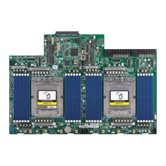
• If you have any questions, please contact our support team at: support@supermicro.com This manual may be periodically updated without notice. Please check the Supermicro website for possible updates to the manual revision level. - Page 8 H13DSH User's Manual Figure 1-1. H13DSH Motherboard Image Note: All graphics shown in this manual were based upon the latest PCB revision available at the time of publication of the manual. The motherboard you received may or may not look...
-
Page 9: Quick Reference
JPW3 JPW4 JPW5 DIMMJ7-J12 DIMMJ13-J18 DIMMJ19-J24 DIMMJ1-J6 FAN9 Figure 1-2. H13DSH Layout Notes: • Components not documented are for internal testing only. • See Chapter 2 for detailed information on jumpers, I/O ports, and JF1 front panel connec- tions. •... -
Page 10: Quick Reference Table
H13DSH User's Manual Quick Reference Table Jumper Description Default Setting JBT1 CMOS Clear Open (Normal) JSATA1 Hybrid MCIO Select Open (NVMe) JSATA2 Hybrid MCIO Select Open (NVMe) Description Status LED_PWR Power LED Solid Green: Power On Green: Blinking (BMC Normal) - Page 11 Chapter 1: Introduction Note: Jumpers, connectors, switches, and LED indicators that are not described in the preceding tables are for manufacturing testing purposes only, and are not covered in this manual.
-
Page 12: Motherboard Features
H13DSH User's Manual Motherboard Features Features • AMD EPYC™ 9004 series processors in Socket SP5 Memory • Twenty-four DIMMs, 6TB Reg. ECC DDR5 up to 4800MHz DIMM Size • Up to 256GB Chipset • System on Chip (SoC) Expansion Slots •... - Page 13 Chapter 1: Introduction Features System Management • IPMIView/SMCIPMITOOL/IPMICFG • SuperDoctor® 5 • SDO/SPM/SSM/SUM-OOB/InBand • Trusted Platform Module (TPM) support LED Indicators • Power / Suspend-state Indicator • UID / Remote UID Dimensions • 17" (W) x 11.5" (L), (431.8 x 292.1 mm)
-
Page 14: Block Diagram
H13DSH User's Manual Block Diagram H13DSH CPU1 P4 [3:0] M.2 Conn M key M.2-H1 MCIO M.2 Conn CPU0 P4 [3:0] CPU1 P3 [7:0] M key CPU1 P3 [15:8] MCIO AIOM1 JUSB1 COM1 RTL8211F CPU0 P3 [15:8] MCIO CPU1 P2 [15:8]... -
Page 15: Processor And Chipset Overview
5nm process architecture, and is optimized for embedded storage solutions, networking applications, or cloud-computing platforms. With support of the new microarchitecture 5nm process technology, the H13DSH drastically increases system performance for a multitude of server applications. -
Page 16: System Health Monitoring
H13DSH User's Manual 1.4 System Health Monitoring This section describes the health monitoring features of the H13DSH motherboard. The motherboard has an onboard Baseboard Management Controller (BMC) chip that supports system health monitoring. Once a voltage becomes unstable, a warning is given or an error message is sent to the screen. -
Page 17: Acpi Features
Chapter 1: Introduction 1.5 ACPI Features ACPI stands for Advanced Configuration and Power Interface. The ACPI specification defines a flexible and abstract hardware interface that provides a standard way to integrate power management features throughout a computer system including its hardware, operating system and application software. -
Page 18: Chapter 2 Installation
H13DSH User's Manual Chapter 2 Installation 2.1 Static-Sensitive Devices Electrostatic Discharge (ESD) can damage electronic com ponents. To prevent damage to your motherboard, it is important to handle it very carefully. The following measures are generally sufficient to protect your equipment from ESD. -
Page 19: Motherboard Installation
Chapter 2: Installation 2.2 Motherboard Installation All motherboards have standard mounting holes to fit different types of chassis. Make sure that the locations of all the mounting holes for both the motherboard and the chassis match. Although a chassis may have both plastic and metal mounting fasteners, metal ones are highly recommended because they ground the motherboard to the chassis. - Page 20 H13DSH User's Manual Figure 2-1. Motherboard Mounting Holes...
-
Page 21: Installing The Motherboard
Chapter 2: Installation Installing the Motherboard 1. Install the I/O shield into the back of the chassis. 2. Locate the mounting holes on the motherboard. See the previous page for the location. 3. Locate the matching mounting holes on the chassis. Align the mounting holes on the motherboard against the mounting holes on the chassis. -
Page 22: Processor And Heatsink Installation
CPU socket cap is in place and none of the socket pins are bent; otherwise, contact your retailer immediately. • Refer to the Supermicro website for updates on CPU support. Installing the Processor and Heatsink 1. Unscrew the screw #1 holding down the force frame. - Page 23 Chapter 2: Installation 2. The spring-loaded force frame will raise up after the screw securing it (#1) is removed. Gently allow it to lift up to its stopping position. 3. Lift the rail frame up by gripping the lift tabs near the front end of the rail frame. While keeping a secure grip of the rail frame, lift it to a position so you can do the next step of removing the external cap.
- Page 24 H13DSH User's Manual 4. Remove the external cap from the rail frame by pulling it upwards through the rail guides on the rail frame. External Cap PnP Cover Cap 5. The CPU package is shipped from the factory with the carrier frame pre-assembled.
- Page 25 Chapter 2: Installation Note: You can only install the CPU inside the socket in one direction with the handle at the top. Make sure that it is properly inserted into the CPU socket before closing the rail frame plate. If it doesn't close properly, do not force it as it may damage your CPU. Instead, open the rail frame plate again, and double-check that the CPU is aligned properly.
- Page 26 H13DSH User's Manual 8. Gently lower the rail frame down onto the socket until the latches on the rail frame engage with the socket housing and it rests in place. DO NOT force it into place! 9. Note that the force frame is spring loaded and has to be held in place before it is secured.
- Page 27 Chapter 2: Installation 10. Place and re-screw the screw to the way you removed them. When finished, the force frame will be secure over both the rail frame and CPU package. 11. After the force frame is secured and the CPU package is in place, now you must install the heatsink to the frame.
- Page 28 H13DSH User's Manual 12. Using a diagonal pattern, tighten the six screws down on the heatsink in a clockwise fashion till it is secure. The heatsink will now be secured and you have finished installing the processor and heatsink onto the motherboard. Repeat this procedure for any remaining CPU sockets on the motherboard.
- Page 29 Chapter 2: Installation Un-installing the Processor and Heatsink 1. Remove the heatsink attached to the top of the CPU package by reversing the installation procedure. 2. Clean the thermal grease left by the heatsink on the CPU package lid to limit the risk of it contaminating the CPU package land pads or contacts in the socket housing.
-
Page 30: Memory Support And Installation
Memory Support The H13DSH supports up to 6TB of ECC DDR5 4800 MT/s speed, RDIMM/LRDIMM/3DS memory in twenty-four slots. Refer to the table below for additional memory information. Note: Check the Supermicro website for possible updates to memory support. - Page 31 Chapter 2: Installation Populating RDIMM/RDIMM 3DS DDR5 Memory Modules with AMD EPYC™ 9004 Series Processors DIMM Population Maximum DIMM Capacity Maximum Frequency Type (MT/s) DIMM1 1 Channel 12 Channels 1R (1 rank) 32GB 384GB 4800 RDIMM 2R (2 ranks) 64GB 768GB 4800 2S2R (4 ranks)
-
Page 32: Dimm Module Population Sequence
H13DSH User's Manual DIMM Module Population Sequence When installing memory modules, the DIMM slots should be populated in the following order: DIMMA1, DIMMB1, DIMMC1, DIMMD1, DIMME1, DIMMF1, then DIMMG1, DIMMH1, DIMMI1, DIMMJ1, DIMMK1, DIMML1. • For optimal performance, use DDR5 DIMM modules of the same type, size and speed. -
Page 33: Dimm Installation
Chapter 2: Installation DIMM Installation 1. Insert the desired number of DIMMs into the memory slots, starting with DIMMA1, DIMMB1, DIMMC1, DIMMD1, DIMME1, DIMMF1, then DIMMG1, DIMMH1, DIMMI1, DIMMJ1, DIMMK1, DIMML1. For best performance, please use the Receptive Point memory modules of the same type and speed. -
Page 34: Connectors
H13DSH User's Manual 2.5 Connectors Power Connections Power Connectors JPW1 is the 8-pin power connector for GPU and NVMe power. JPW2 and JPW3 are the 8-pin 12V DC power connectors on the motherboard that provide adequate power supply to your system. -
Page 35: Headers
SPI_IRQ# NVMe Ports (NVMe P1_0~7, P2_0~11) The H13DSH has 20 NVMe ports (2 ports per 1 MCIO x 8) on the motherboard. These ports provide high speed and low latency directly from the CPU to NVMe Solid State (SSD) drives. - Page 36 H13DSH User's Manual SATA/NVMe Hybrid Ports (P1_NVMe 0/1, P1_SATA 0-7; P1_NVMe 2/3, P1_SATA 8-15; P2_NVMe 0/1, P2_SATA 0-7; P2_NVMe 2/3, P2_SATA8-15) Each SATA/NVMe hybrid port can support up to eight SATA 3.0 ports or two NVMe ports (PCIe x4), for a total of thirty-two SATA ports or eight NVMe ports.
-
Page 37: Jumper Settings
Chapter 2: Installation 2.6 Jumper Settings How Jumpers Work To modify the operation of the motherboard, jumpers can be used to choose between optional settings. Jumpers create shorts between two pins to change the function of the connector. Pin #1 is identified with a square solder pad on the printed circuit board. See the diagram below for an example of jumping pins 1 and 2. - Page 38 H13DSH User's Manual JSATA1/JASAT2 The 3-pin jumpers at JSATA1 and JSATA2 provide the option to switch the hybrid port (JMCIO 1/2/5/6) between SATA/NVMe. Refer to the table below for pin definitions. JSATA1/JSATA2 Pin Definitions Pin# Definition Auto (Depends on system configuration)
-
Page 39: Led Indicators
Chapter 2: Installation 2.7 LED Indicators Onboard Power LED LED_PWR is an onboard power LED. When this LED is lit, it means system is in the power- on state, and the onboard power status is ok. Turn off the system and unplug the power cord before removing or installing components. -
Page 40: Chapter 3 Troubleshooting
H13DSH User's Manual Chapter 3 Troubleshooting 3.1 Troubleshooting Procedures Use the following procedures to troubleshoot your system. If you have followed all of the procedures below and still need assistance, refer to the ‘Technical Support Procedures’ and/ or ‘Returning Merchandise for Service’ section(s) in this chapter. Always disconnect the AC power cord before adding, changing or installing any non hot-swap hardware components. -
Page 41: No Video
Chapter 3: Troubleshooting No Video 1. Check that the VGA cable is connected properly, and the monitor is on. 2. Check if you follow the guidelines to install the memory module (see DIMM Module Population in chapter 2). 3. Reseat the memory DIMM module. Note: If you are a system integrator, VAR or OEM, a POST diagnostics card is recommended. -
Page 42: When The System Becomes Unstable
H13DSH User's Manual 3. If the above steps do not fix the setup configuration problem, contact your vendor for repairs. When the System Becomes Unstable A. If the system becomes unstable during or after OS installation, check the following: 1. CPU/BIOS support: Make sure that your CPU is supported and that you have the latest BIOS installed in your system. -
Page 43: Technical Support Procedures
Chapter 3: Troubleshooting 5. Check and change one component at a time instead of changing several items at the same time. This will help isolate and identify the problem. 6. To find out if a component is good, swap this component with a new one to see if the system will work properly. -
Page 44: Frequently Asked Questions
3.3 Frequently Asked Questions Question: What type of memory does my motherboard support? Answer: The H13DSH motherboard supports up to 6TB of ECC DDR5 4800 MT/s speed, RDIMM/LRDIMM/3DS in twelve slots. See Section 2.4 for details on installing memory. Question: How do I update my BIOS? Answer: It is recommended that you do not upgrade your BIOS if you are not experiencing any problems with your system. - Page 45 Chapter 3: Troubleshooting Question: Why are the numbering of NVMe storage devices not shown as sequential in the operating system? Answer: This only happens after an M.2 NVMe device is installed. In the example of a twelve-bay system, NVMe4 (from CPU1) is occupied and NVMe9 (from CPU2) is occupied, causing the numbering of the NVMe storage devices in the operating system to be different from that of the physical presence of drives.
-
Page 46: Returning Merchandise For Service
H13DSH User's Manual 3.4 Returning Merchandise for Service A receipt or copy of your invoice marked with the date of purchase is required before any warranty service will be rendered. You can obtain service by calling your vendor for a Returned Merchandise Authorization (RMA) number. -
Page 47: Battery Installation
Chapter 3: Troubleshooting Battery Installation 1. To install an onboard battery, follow the steps 1 & 2 above and continue below: 2. Identify the battery's polarity. The positive (+) side should be facing up. 3. Insert the battery into the battery holder and push it down until you hear a click to ensure that the battery is securely locked. -
Page 48: Chapter 4 Bios
BIOS 4.1 Introduction This chapter describes the AMIBIOS™ Setup utility for the H13DSH motherboard. The BIOS is stored on a chip and can be easily upgraded using a flash program. Note: Due to periodic changes to the BIOS, some settings may have been added or deleted and might not yet be recorded in this manual. -
Page 49: Main Setup
Chapter 4: BIOS 4.2 Main Setup When you first enter the AMI BIOS setup utility, you will enter the Main setup screen. You can always return to the Main setup screen by selecting the Main tab on the top of the screen. The Main BIOS setup screen is shown below. - Page 50 H13DSH User's Manual Supermicro H13DSH BIOS Version This item displays the version of the BIOS ROM used in the system. Build Date This item displays the date when the version of the BIOS ROM used in the system was built.
-
Page 51: Advanced
Chapter 4: BIOS 4.3 Advanced Use the arrow keys to select Boot Setup and press <Enter> to access the submenu items. Warning: Take caution when changing the Advanced settings. An incorrect value, a very high DRAM frequency, or an incorrect DRAM timing setting may make the system unstable. - Page 52 H13DSH User's Manual Bootup NumLock State Use this feature to select the keyboard <Numlock> state. The options are On and Off. Wait For "F1" If Error Use this feature to force the system to wait until the 'F1' key is pressed if an error occurs.
- Page 53 Chapter 4: BIOS CPU Configuration CPU Configuration SMT Control Use this setting to specify Symmetric Multithreading. Options include Disabled and Auto. Core Performance Boost This setting is used to configure for Core Performance Boost. Options include Disabled and Auto. Global C-state Control This setting is used to configure for Global C-state Control.
- Page 54 H13DSH User's Manual L1 Stream HW Prefetcher / L2 Stream HW Prefetcher This setting is used to enable or disable the L1/L2 Stream Hardware Prefetcher. The options are Disabled, Enabled and Auto. CCD Control Use this setting to disable CCDs in the CPU. Options include Auto, 2 CCDs, 4 CCDs, 6CCDs, 8 CCDs and 10 CCDs.
- Page 55 Chapter 4: BIOS CPU1 PCIe Package Group P3 This setting selects the PCIe port bifurcation configuration for the selescted slot. The options include Auto, x4x4x4x4, x4x4x8, x8x4x4, x8x8 and x16. CPU1 PCIe Package Group G3 This setting selects the PCIe port bifurcation configuration for the selescted slot. The options include Auto, x4x4x4x4, x4x4x8, x8x4x4, x8x8, x16, and SATA.
- Page 56 H13DSH User's Manual Power Profile Selection Options include High Performance Mode, Efficiency Mode and Maximum IO Performance Mode. DF Cstats Use this setting to enable/disable DF Cstates. Options include Disabled, Enabled, and Auto. Data Link Feature Cap Use this setting to set Data Link Feature Cap. Options include Enabled, Disabled and Auto.
- Page 57 Chapter 4: BIOS CPU1 Memory Information CPU1 Memory Information These sections are for informational purposes. They will display some details about the detected memory according to each CPU on the motherboard, such as: • Detected Size (per slot, in MB) •...
- Page 58 H13DSH User's Manual ACPI SRAT L3 Cache As NUMA Domain Use this setting to enabe/disable ACPI SRAT L3 Cache As NUMA Domain. The options are Disabled, Enabled and Auto. Super IO Configuration Super IO Configuration The following Super IO information will display: Super IO Chip AST2600 Serial Port 1 Configuration...
- Page 59 Chapter 4: BIOS Serial Port Console Redirection COM1 Console Redirection Select Enabled to enable console redirection support for a serial port specified by the user. The options are Disabled and Enabled. (If the above is set to Enabled, this option becomes available.) Console Redirection Settings Terminal Type This feature allows the user to select the target terminal emulation type for Console...
- Page 60 H13DSH User's Manual Flow Control Use this feature to set the flow control for Console Redirection to prevent data loss caused by buffer overflow. Send a "Stop" signal to stop sending data when the receiving buffer is full. Send a "Start" signal to start sending data when the receiving buffer is empty. The options are None and Hardware RTS/CTS.
- Page 61 Chapter 4: BIOS Console Redirection Settings Terminal Type This feature allows the user to select the target terminal emulation type for Console Redirection. Select VT100 to use the ASCII Character set. Select VT100+ to add color and function key support. Select ANSI to use the Extended ASCII Character Set. Select VT-UTF8 to use UTF8 encoding to map Unicode characters into one or more bytes.
- Page 62 H13DSH User's Manual Recorder Mode Select Enabled to capture the data displayed on a terminal and send it as text messages to a remote server. The options are Disabled and Enabled. Resolution 100x31 Select Enabled for extended-terminal resolution support. The options are Disabled and Enabled.
- Page 63 Chapter 4: BIOS Console Redirection Settings Out-of-Band Mgmt Port The feature selects a serial port in a client server to be used by the Microsoft Windows Emergency Management Services (EMS) to communicate with a remote host server. The options include COM1 and SOL. Terminal Type Use this feature to select the target terminal emulation type for Console Redirection.
- Page 64 H13DSH User's Manual PCIe/PCI/PnP Configuration This menu provides PCIe/PCI/PnP configuration settings and information. PCI Bus Driver Version PCI Devices Common Settings Above 4G Decoding This setting Disables or Enables 64-bit capable devices ability to be decoded in above 4G address space (only if the system supports 64-bit PCI decoding). The options are Disabled and Enabled.
- Page 65 Chapter 4: BIOS No Snoop Select Enable to support no-snoop mode for each CB device. The options are Disabled and Enabled. VGA Priority Use this setting to select between onboard or external VGA support. The options are Onboard and External. PCIe Ten Bit Tag Support Use this setting to Disable, Enable or Auto control the PCIe ten bit tags for supported devices.
- Page 66 H13DSH User's Manual Port 60/64 Emulation Select Enabled for I/O port 60h/64h emulation support, which in turn, will provide complete legacy USB keyboard support for the operating systems that do not support legacy USB devices. The options are Disabled and Enabled.
- Page 67 Chapter 4: BIOS SATA Configuration SATA Configuration SATA Configuration SATA Enable Use this setting to disable or enable OnChip SATA controller. Options include Disabled, Enabled, and Auto. SATA Information Indications SATA devices information. SATA Controller HTTP Boot Configuration HTTP Boot Configuration HTTP Boot Policy Sets the HTTP boot policy to Apply to all LANs, Apply to each LAN, or Boot Priority #1 instantly.
- Page 68 Enter IP4 address in dotted-decimal notation. Supermicro KMS TCP Port number Enter Supermicro KMS TCP port number. The default value is 5696. KMS Time Out KMS Server connecting time-out, unit is second, in the range of 5~30 seconds. The default value is 5.
- Page 69 Chapter 4: BIOS Client Private Key Enroll factory defaults or load the KMS TLS certificates from the file. The options include Update, Delete and Export. TLS Authenticate Configuration This submenu allows the user to configure Transport Layer Security (TLS) settings. Server CA Configuration Enroll Certification Enroll Certification Using File...
-
Page 70: Bmc
H13DSH User's Manual 4.4 BMC This tab allows you to configure the following IPMI settings for the system. Use this feature to configure Intelligent Platform Management Interface (IPMI) settings. BMC Firmware Revision This item indicates the IPMI firmware revision used in your system. - Page 71 Chapter 4: BIOS Erasing Settings Erase SEL Select Yes, On next reset to erase all system event logs upon next system reboot. Select Yes, On every reset to erase all system event logs upon each system reboot. Select No to keep all system event logs after each system reboot.
- Page 72 H13DSH User's Manual Subnet Mask This item displays the sub-network that this computer belongs to. The value of each three- digit number separated by dots should not exceed 255. Station MAC Address This item displays the Station MAC address for this computer. Mac addresses are 6 two-digit hexadecimal numbers.
- Page 73 Chapter 4: BIOS Current Configuration Address Source The default value is Disabled. VLAN ID The default value is 1.
-
Page 74: Event Logs
H13DSH User's Manual 4.5 Event Logs This tab allows the user to configure the following event logs settings for the system. Change SMBIOS Event Log Settings This feature allows the user to configure SMBIOS Event settings. Enabling/Disabling Options SMBIOS Event Log Select Enabled to enable SMBIOS (System Management BIOS) Event Logging during system boot. - Page 75 Chapter 4: BIOS When Log is Full Select Erase Immediately to immediately erase all errors in the SMBIOS event log when the event log is full. Select Do Nothing for the system to do nothing when the SMBIOS event log is full. The options are Do Nothing and Erase Immediately. SMBIOS Event Log Standard Settings Log System Boot Event Select Enabled to log system boot events.
-
Page 76: Security
H13DSH User's Manual 4.6 Security This tab allows you to configure the following security settings for the system. Administrator Password Press <Enter> to create a new, or change an existing Administrator password. Note that if the Administrator Password is erased, the User Password will be cleared as well. - Page 77 Chapter 4: BIOS Secure Boot This section contains options and menus for securing your boot mode and for key management. Secure Boot This option allows you specify when the Platform Key (PK) is enrolled. When enabled, the System Mode is user deployed, and the CSM function is disabled. Options include Disabled and Enabled.
- Page 78 H13DSH User's Manual Reset To Setup Mode Enroll Efi Image This feature is to enroll SHA256 hash of the binary into the Authorized Signature Data- base (DB) and to allow the image to run in the secure boot mode. Export Secure Boot Variables Use this feature to export NVRAM content of secure boot variables to files in a root folder on a file system device.
- Page 79 Chapter 4: BIOS Forbidden Signatures (dbx) This feature allows the user to enter and configure a set of values to be used as Forbid- den Signatures for the system. These values also indicate sizes, keys numbers, and key sources of the forbidden signatures. Select Update to update your "Forbidden. Signa- tures".
-
Page 80: Boot Settings
H13DSH User's Manual 4.7 Boot Settings Use this tab to configure Boot Settings: Boot Mode Select Use this item to select the type of device that the system is going to boot from. The options are Legacy, UEFI, and Dual. The default setting is UEFI. - Page 81 Chapter 4: BIOS Delete Boot Option Use this feature to remove a pre-defined boot device from which the system will boot during startup. The default is Select one to Delete. UEFI Application Boot Priorities This feature allows a user to specify the Boot Device Priority sequence from available UEFI Application.
-
Page 82: Save & Exit
H13DSH User's Manual 4.8 Save & Exit Select the Save & Exit tab to enter the Save & Exit BIOS Setup screen. Save Options Discard Changes and Exit Select this option to quit the BIOS Setup without making any permanent changes to the system configuration, and reboot the computer. - Page 83 Chapter 4: BIOS Default Options Restore Optimized Defaults To set this feature, select Restore Defaults from the Save & Exit menu and press <Enter>. These are factory settings designed for maximum system stability, but not for maximum performance. Save as User Defaults To set this feature, select Save as User Defaults from the Exit menu and press <Enter>.
-
Page 84: Appendix A Software
1. Create a method to access the Microsoft Windows installation ISO file. That can be a USB flash or media drive. 2. Go to the Supermicro web page for your motherboard and click on "Download the Latest Drivers and Utilities," select the proper driver, and copy it to a USB flash drive. - Page 85 Appendix A: Software 4. During Windows Setup, continue to the dialog where you select the drives on which to install Windows. If the disk you want to use is not listed, click on “Load driver” link at the bottom left corner. Figure A-2.
- Page 86 The Supermicro website contains drivers and utilities for your system at https://www. supermicro.com/wdl/. Some of these must be installed, such as the chipset driver. After accessing the website, go into the CDR_Images (in the parent directory of the above link) and locate the ISO file for your motherboard. Download this file to a USB flash or media drive.
- Page 87 A.3 SuperDoctor ® The Supermicro SuperDoctor 5 is a program that functions in a command-line or web-based interface for Windows and Linux operating systems. The program monitors such system health information as CPU temperature, system voltages, system power consumption, fan speed, and provides alerts via email or Simple Network Management Protocol (SNMP).
-
Page 88: Appendix B Standardized Warning Statements
The following statements are industry standard warnings, provided to warn the user of situations which have the potential for bodily injury. Should you have questions or experience difficulty, contact Supermicro's Technical Support department for assistance. Only certified technicians should attempt to install or configure components. - Page 89 Appendix B: Warning Statements Attention Danger d'explosion si la pile n'est pas remplacée correctement. Ne la remplacer que par une pile de type semblable ou équivalent, recommandée par le fabricant. Jeter les piles usagées conformément aux instructions du fabricant. ¡Advertencia! Existe peligro de explosión si la batería se reemplaza de manera incorrecta.
- Page 90 H13DSH User's Manual B.2 Product Disposal Warning! Ultimate disposal of this product should be handled according to all national laws and regulations. 製品の廃棄 この製品を廃棄処分する場合、 国の関係する全ての法律 ・ 条例に従い処理する必要があります。 警告 本产品的废弃处理应根据所有国家的法律和规章进行。 警告 本產品的廢棄處理應根據所有國家的法律和規章進行。 Warnung Die Entsorgung dieses Produkts sollte gemäß allen Bestimmungen und Gesetzen des Landes erfolgen.
Need help?
Do you have a question about the H13DSH and is the answer not in the manual?
Questions and answers