Table of Contents
Advertisement
Quick Links
Advertisement
Table of Contents

Subscribe to Our Youtube Channel
Related Manuals for Supermicro H13SSF


Summary of Contents for Supermicro H13SSF
- Page 1 H13SSF USER’S MANUAL Revision 1.0a...
- Page 2 Super Micro Computer, Inc. ("Supermicro") reserves the right to make changes to the product described in this manual at any time and without notice. This product, including software and documentation, is the property of Supermicro and/or its licensors, and is supplied only under a license.
- Page 3 It provides information for the installation and use of the H13SSF motherboard. About This Motherboard Built upon the functionality and capability of the AMD EPYC™ processor, the H13SSF motherboard provides superior graphics capability and system performance while consuming little power. Please note that this motherboard is intended to be installed and serviced by certified service technicians only.
-
Page 4: Contacting Supermicro
San Jose, CA 95131 U.S.A. Tel: +1 (408) 503-8000 Fax: +1 (408) 503-8008 Email: marketing@supermicro.com (General Information) Sales-USA@supermicro.com (Sales Inquiries) Government_Sales-USA@supermicro.com (Gov. Sales Inquiries) support@supermicro.com (Technical Support) RMA@supermicro.com (RMA Support) Webmaster@supermicro.com (Webmaster) Website: www.supermicro.com Europe Address: Super Micro Computer B.V. -
Page 5: Table Of Contents
Preface Table of Contents Contacting Supermicro ......................4 Chapter 1 Introduction 1.1 Quick Reference ........................9 Quick Reference Table ......................10 Motherboard Features .......................11 Block Diagram ........................13 1.2 Processor and Chipset Overview ..................14 1.3 Special Features ........................14 Recovery from AC Power Loss ..................14 1.4 System Health Monitoring ....................15... - Page 6 Preface 2.5 Connectors .........................33 Power Connections ......................33 Headers ..........................34 2.6 LED Indicators ........................35 2.7 M.2 Solid State Drive Installation ..................36 Chapter 3 Troubleshooting 3.1 Troubleshooting Procedures ....................37 Before Power On ......................37 No Power ..........................37 No Video ...........................38 System Boot Failure ......................38 Memory Errors ........................38 The System Cannot Retain the Setup Configuration ............38 When the System Becomes Unstable ................39...
-
Page 7: Chapter 1 Introduction
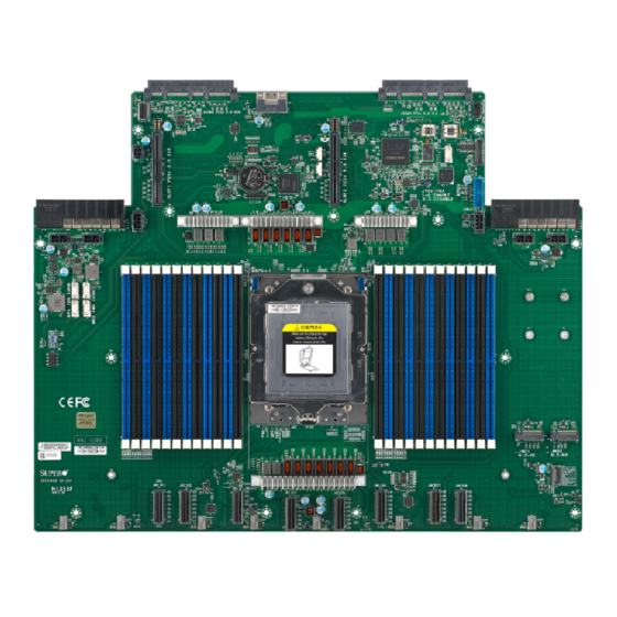
Chapter 1 Introduction Congratulations on purchasing your computer motherboard from an industry leader. Supermicro boards are designed to provide you with the highest standards in quality and performance. If anything listed is damaged or missing, please contact your retailer. Important Links For your system to work properly, please follow the links below to download all necessary drivers/utilities and the user’s manual for your server. - Page 8 Chapter 1: Introduction Figure 1-1. H13SSF Motherboard Image Note: All graphics shown in this manual were based upon the latest PCB revision available at the time of publication of the manual. The motherboard you received may or may not look...
-
Page 9: Quick Reference
FAN1 JMCIO8 FAN3 FAN7 JMCIO5 JMCIO3 JMCIO4 JMCIO2 Figure 1-2. H13SSF Layout Notes: • Components not documented are for internal testing only. • Chapter 2 for detailed information on jumpers and I/O ports. • Use only the correct type of onboard CMOS battery as specified by the manufacturer. To... -
Page 10: Quick Reference Table
NVMe VPP and BMC I C Header JNVI2C1 Riser card SMBus Header JAIOM1-JAIOM2 Supermicro® Advanced I/O Module (AIOM PCIe 5.0 x16) Slots JSXB0-1 Slot 1-2 PCIe 5.0 x16 Eight MCIO (PCIe 5.0 x8) Connectors JMCIO1-8 MCIO1: JDBG2 / MCIO5: JDBG3 / MCIO6: JDBG4... -
Page 11: Motherboard Features
Chapter 1: Introduction Motherboard Features • Single AMD EPYC™ processor in Socket SP5 Memory • Up to 6 TB registered ECC DDR5 4800 MT/s speed in 24 DIMM slots (2DPC) DIMM Size • Up to 256 GB Chipset • System on Chip (SoC) Expansion Slots •... - Page 12 Chapter 1: Introduction System Management • IPMIView / SMCIPMITOOL / IPMICFG • SuperDoctor® 5 • SDO / SPM / SSM / SUM-OOB / InBand • Trusted Platform Module (TPM) support LED Indicators • CPU / System Overheat LED • Power / Suspend-state Indicator •...
-
Page 13: Block Diagram
Chapter 1: Introduction Block Diagram V V G G A A c c o o n n n n R R J J 4 4 5 5 c c o o n n n n S S l l o o t t 3 3 ( ( A A I I O O M M ) ) S S l l o o t t 4 4 ( ( A A I I O O M M ) ) R R e e a a r r I I O O S S A A T T A A c c o o n n n n... -
Page 14: Processor And Chipset Overview
5-nm process architecture, and is optimized for embedded storage solutions, networking applications, or cloud-computing platforms. With support of the new microarchitecture 5-nm process technology, the H13SSF drastically increases system performance for a multitude of server applications. The 4th Gen EPYC processor supports the following features: •... -
Page 15: System Health Monitoring
Chapter 1: Introduction 1.4 System Health Monitoring This section describes the health monitoring features of the H13SSF motherboard. The motherboard has an onboard Baseboard Management Controller (BMC) chip that supports system health monitoring. Once a voltage becomes unstable, a warning is given or an error message is sent to the screen. -
Page 16: Acpi Features
Chapter 1: Introduction 1.5 ACPI Features ACPI stands for Advanced Configuration and Power Interface. The ACPI specification defines a flexible and abstract hardware interface that provides a standard way to integrate power management features throughout a computer system including its hardware, operating system and application software. -
Page 17: Chapter 2 Installation
Chapter 2: Installation Chapter 2 Installation 2.1 Static-Sensitive Devices Electrostatic Discharge (ESD) can damage electronic com ponents. To prevent damage to your motherboard, it is important to handle it very carefully. The following measures are generally sufficient to protect your equipment from ESD. Precautions •... -
Page 18: Motherboard Installation
Chapter 2: Installation 2.2 Motherboard Installation All motherboards have standard mounting holes to fit different types of chassis. Make sure that the locations of all the mounting holes for both the motherboard and the chassis match. Although a chassis may have both plastic and metal mounting fasteners, metal ones are highly recommended because they ground the motherboard to the chassis. - Page 19 Chapter 2: Installation Figure 2-1. Motherboard Mounting Holes...
-
Page 20: Installing The Motherboard
Chapter 2: Installation Installing the Motherboard 1. Locate the mounting holes on the motherboard. See the previous page for the location. 2. Locate the matching mounting holes on the chassis. Align the mounting holes on the motherboard against the mounting holes on the chassis. 3. -
Page 21: Processor And Heatsink Installation
CPU socket cap is in place and none of the socket pins are bent; otherwise, contact your retailer immediately. • Refer to the Supermicro website for updates on CPU support. Installing the Processor and Heatsink 1. Unscrew the screw #1 holding down the force frame. - Page 22 Chapter 2: Installation 2. The spring-loaded force frame will raise up after the screw securing it (#1) is removed. Gently allow it to lift up to its stopping position. Force Frame 3. Lift the rail frame up by gripping the lift tabs near the front end of the rail frame. While keeping a secure grip of the rail frame, lift it to a position so you can do the next step of removing the external cap.
- Page 23 Chapter 2: Installation 4. Remove the external cap from the rail frame by pulling it upwards through the rail guides on the rail frame. External Cap 5. The CPU package is shipped from the factory with the carrier frame pre-assembled. Grip the handle of the carrier frame/CPU package assembly from its shipping tray, and while gripping the handle, align the flanges of the carrier frame onto the rails of the rail frame so its pins will be at the bottom when the rail frame is lowered later.
- Page 24 Chapter 2: Installation Note: You can only install the CPU inside the socket in one direction with the handle at the top. Make sure that it is properly inserted into the CPU socket before closing the rail frame plate. If it doesn't close properly, do not force it as it may damage your CPU. Instead, open the rail frame plate again, and double-check that the CPU is aligned properly.
- Page 25 Chapter 2: Installation 8. Gently lower the rail frame down onto the socket until the latches on the rail frame engage with the socket housing and it rests in place. DO NOT force it into place! 9. Note that the force frame is spring loaded and has to be held in place before it is secured.
- Page 26 Chapter 2: Installation 10. Replace and tighten the screws in the same order they were removed. When finished, the force frame will be secure over both the rail frame and CPU package. 11. After the force frame is secured and the CPU package is in place, now you must install the heatsink to the frame.
- Page 27 Chapter 2: Installation 12. Using a diagonal pattern, tighten the six screws down on the heatsink in a clockwise fashion until secure. The heatsink will now be secured and you have finished installing the processor and heatsink onto the motherboard. Repeat this procedure for any remaining CPU sockets on the motherboard.
- Page 28 Chapter 2: Installation Un-installing the Processor and Heatsink 1. Remove the heatsink attached to the top of the CPU package by reversing the installation procedure. 2. Clean the thermal grease left by the heatsink on the CPU package lid to limit the risk of it contaminating the CPU package land pads or contacts in the socket housing.
-
Page 29: Memory Support And Installation
Memory Support The H13SSF supports RDIMM / 3DS RDIMM in 24 DIMM slots. Up to 3 TB of ECC DDR5 4800 MT/s speed in 12 DIMM slots (1 DPC) or up to 6TB of ECC DDR5 4000 MT/s / 3600 MT/s speed in 24 DIMM slots (2 DPC). - Page 30 Chapter 2: Installation Populating RDIMM/RDIMM 3DS DDR5 Memory Modules with AMD EPYC 9004 series Processor DIMM Population Maximum DIMM Capacity (GB) DIMM Type Maximum Frequency (MT/s) DIMM1 DIMM2 1 Channel 12 Channels 32 GB 384 GB 4800 64 GB 768 GB 4000 RDIMM 64 GB...
-
Page 31: Dimm Module Population Sequence
Chapter 2: Installation DIMM Module Population Sequence There is no specific order or sequence required when installing memory modules. However, do keep the following in mind: • The blue slots must be populated first, follow the DIMM Population Guide. • It is recommended that DDR5 DIMM modules of the same type, size, and speed should be installed. -
Page 32: Dimm Installation
Chapter 2: Installation DIMM Installation 1. Insert the desired number of DIMMs into the memory slots. See Memory Support for details on memory population guidelines. 2. Push the release tabs outwards on both ends of the DIMM slot to unlock it. Receptive Point 3. -
Page 33: Connectors
Chapter 2: Installation 2.5 Connectors Power Connections 12 V 8-pin Auxiliary Power Connector (JPW1-2, 4-7) JPW1-2 and 4-7 are 8-pin Micro-Hi power input to provide power to GPU. Refer to the table below for pin definitions. 12 V 8-pin Power Connector Pin Definitions Pin# Definition... -
Page 34: Headers
Port 80 connection. Use this header to enhance system performance and data security. Refer to the table below for pin definitions. Please go to the following link for more information on the TPM: http://www.supermicro.com/manuals/other/TPM.pdf. Trusted Platform Module Header Pin Definitions... -
Page 35: Led Indicators
Chapter 2: Installation 2.6 LED Indicators BMC LAN Port LEDs A dedicated BMC LAN is located on the rear I/O panel and has two LED indicators. The LED on the right indicates connection and activity, while the LED on the left indicates the speed of connection. -
Page 36: Solid State Drive Installation
Chapter 2: Installation 2.7 M.2 Solid State Drive Installation Installing Dual M.2 SSDs 1. Disconnect power from the motherboard or system. 2. Refer to the motherboard layout and locate the two M.2 dual slots (JMD1 & JMD2). 3. Insert the lower M.2 sideways into the connector so that it lays flat, then follow the instructions below from 4. -
Page 37: Chapter 3 Troubleshooting
Chapter 3: Troubleshooting Chapter 3 Troubleshooting 3.1 Troubleshooting Procedures Use the following procedures to troubleshoot your system. If you have followed all of the procedures below and still need assistance, refer to the 'Technical Support Procedures' and/ 'Returning Merchandise for Service' section(s) in this chapter. -
Page 38: No Video
Chapter 3: Troubleshooting No Video 1. Check that the VGA cable is connected properly, and the monitor is on. 2. Check if you follow the guidelines to install the memory module (see DIMM Module Population in Chapter 3. Reseat the memory DIMM modules. Note: If you are a system integrator, VAR or OEM, a POST diagnostics card is recommended. -
Page 39: When The System Becomes Unstable
2. Memory support: Make sure that the memory modules are supported by testing the modules using memtest86 or a similar utility. Note: Refer to the product page on our website at http://www.supermicro.com for memory and CPU support and updates. 3. Storage drives support: Make sure that all storage drives work properly. Replace the bad storage drives with good ones. -
Page 40: Technical Support Procedures
Chapter 3: Troubleshooting component in question in another system. If the new system works, the component is good and the old system has problems. 3.2 Technical Support Procedures Before contacting Technical Support, please take the following steps. Also, note that as a motherboard manufacturer, we do not sell directly to end-users, so it is best to first check with your distributor or reseller for troubleshooting services. -
Page 41: Frequently Asked Questions
3.3 Frequently Asked Questions Question: What type of memory does my motherboard support? Answer: The H13SSF motherboard supports up to 6 TB of ECC DDR5 4800 MT/s speed, RDIMM/3DS RDIMM in 24 slots. See Section 2.4 for details on installing memory. -
Page 42: Returning Merchandise For Service
Shipping and handling charges will be applied for all orders that must be mailed when service is complete. For faster service, RMA authorizations may be requested online (http://www.supermicro.com/ support/rma/). This warranty only covers normal consumer use and does not cover damages incurred in shipping or from failure due to the alteration, misuse, abuse or improper maintenance of products. -
Page 43: Proper Battery Disposal
Chapter 3: Troubleshooting Proper Battery Disposal Please handle used batteries carefully. Do not damage the battery in any way; a damaged battery may release hazardous materials into the environment. Do not discard a used battery in the garbage or a public landfill. Please comply with the regulations set up by your local hazardous waste management agency to dispose of your used battery properly. -
Page 44: Chapter 4 Bios
BIOS 4.1 Introduction This chapter describes the AMIBIOS™ Setup utility for the H13SSF motherboard. The BIOS is stored on a chip and can be easily upgraded using a flash program. Note: Due to periodic changes to the BIOS, some settings may have been added or deleted and might not yet be recorded in this manual. -
Page 45: Main Setup
Chapter 4: BIOS 4.2 Main Setup When you first enter the AMI BIOS setup utility, you will enter the Main setup screen. You can always return to the Main setup screen by selecting the Main tab on the top of the screen. The Main BIOS setup screen is shown below. - Page 46 Chapter 4: BIOS Supermicro H13SSF BIOS Version This item displays the version of the BIOS ROM used in the system. Build Date This item displays the date when the version of the BIOS ROM used in the system was built.
-
Page 47: Advanced
Chapter 4: BIOS 4.3 Advanced Use the arrow keys to select Boot Setup and press <Enter> to access the submenu items. Warning: Take caution when changing the Advanced settings. An incorrect value, a very high DRAM frequency, or an incorrect DRAM timing setting may make the system unstable. - Page 48 Chapter 4: BIOS Bootup NumLock State Use this feature to select the keyboard <Numlock> state. The options are On and Off. Wait For "F1" If Error Use this feature to force the system to wait until the 'F1' key is pressed if an error occurs. The options are Disabled and Enabled.
- Page 49 Chapter 4: BIOS CPU Configuration CPU Configuration SMT Control Use this setting to specify Symmetric Multithreading. Options include Disabled, Enabled, and Auto. Core Performance Boost This setting is used to configure for Core Performance Boost. Options include Disabled and Auto. Global C-state Control This setting is used to configure for Global C-state Control.
- Page 50 Chapter 4: BIOS L1 Stream HW Prefetcher / L2 Stream HW Prefetcher This setting is used to enable or disable the L1/L2 Stream Hardware Prefetcher. The options are Disabled, Enabled, and Auto. CCD Control Use this setting to disable CCDs in the CPU. Options include Auto, 2 CCDs, 4 CCDs, 6 CCDs, 8 CCDs, and 10 CCDs.
- Page 51 Chapter 4: BIOS CPU1 PCIe Package Group G3 This setting selects the PCIe port bifurcation configuration for the selescted slot. The options include Auto, x2x2x2x2x2x2x2x2, x4x4x4x4, x4x4x8, x8x4x4, x8x8, x16, and SATA. CPU1 PCIe Package Group P1 This setting selects the PCIe port bifurcation configuration for the selescted slot. The options include Auto, x2x2x2x2x2x2x2x2, x4x4x4x4, x4x4x8, x8x4x4, x8x8, and x16.
- Page 52 Chapter 4: BIOS ACS Enable AER must be enabled for ACS enable to work. Options include Enabled, Disabled, and Auto. TDP Control Options include Manual and Auto. Package Power Limit Control Use this setting for Package Power Limit Control. Options include Manual and Auto. Determinism Control Use this setting to configure the Determinism Slider.
- Page 53 Chapter 4: BIOS BankSwapMode This setting controls the Bank Swap Mode. The options are Auto, Disabled, and Swap CPU. Power Down Enable Use this setting to enable or disable DDR power down mode. The options are Disabled, Enabled, and Auto. DRAM Scrub Time This setting provides a value that is the number of hours to scrub memory.
- Page 54 Chapter 4: BIOS ACPI Settings ACPI Settings High Precision Event Timer The High Precision Event Timer (HPET) can produce periodic interrupts and is used to synchronize multimedia streams, providing smooth playback and reducing the need to use other timestamp calculations. The options are Disabled and Enabled. PCI AER Support Enbles Advanced error reporting capability.
- Page 55 Chapter 4: BIOS Serial Port 2 Configuration Serial Port 2 Configuration Serial Port Select Enabled to enable the selected onboard serial port. The options are Disabled and Enabled. Change Settings This feature specifies the base I/O port address and the Interrupt Request address of a serial port specified by the user.
- Page 56 Chapter 4: BIOS Data Bits Use this feature to set the data transmission size for Console Redirection. The options are 7 and 8. Parity Options include None, Even, Odd, Mark, and Space. Stop Bits The setting indicates the end of a serial data packet. (A start bit indicates the beginning.) The standard setting is one stop bit.
- Page 57 Chapter 4: BIOS Legacy Serial Redirection Port The default is COM1. Console Redirection The options are Disabled and Enabled. PCIe/PCI/PnP Configuration This menu provides PCIe/PCI/PnP configuration settings and information. PCI Bus Driver Version: A5.01.28 PCI Devices Common Settings: Above 4G Decoding This setting Disables or Enables 64-bit capable devices ability to be decoded in above 4G address space (only if the system supports 64-bit PCI decoding).
- Page 58 Chapter 4: BIOS Relaxed Ordering Select Enable to enable Relaxed Ordering support, which will allow certain transactions to violate the strict-ordering rules of PCI bus for a transaction to be completed prior to other transactions that have already been enqueued. The options are Disabled and Enabled. Clock Spread Spectrum Use this setting to Disable or Enable CG1_PLL Spread Spectrum for your system.
- Page 59 Chapter 4: BIOS XHCI Hand-Off This is a work-around solution for operating systems that do not support XHCI (Extensible Host Controller Interface) hand-off. The XHCI ownership change should be claimed by the XHCI driver. The options are Enabled and Disabled. Port 60/64 Emulation Select Enabled for I/O port 60h/64h emulation support, which in turn, will provide complete legacy USB keyboard support for the operating systems that do not support legacy USB...
- Page 60 Chapter 4: BIOS SATA Configuration ASMedia SATA Controller Hot-Plug Use this setting to enable or disable the hot-plug support. SATA Information Shows SATA devices information. HTTP Boot Configuration HTTP Boot Configuration HTTP Boot Policy Sets the HTTP boot policy to Apply to all LANs, Apply to each LAN, or Boot Priority #1 instantly.
- Page 61 Enter IP4 address in dotted-decimal notation. Supermicro KMS TCP Port number Enter Supermicro KMS TCP port number. The default value is 5696. KMS Time Out KMS Server connecting time-out, unit is second, in the range of 5~30 seconds. The default value is 5.
- Page 62 Chapter 4: BIOS Super-Guardians Configuration Super-Guardians Protection Policy Options include Storage, System, System and Storage. KMS Security Policy Options include Disabled and Enabled. KMS Server Retry Count Test connection to Key Manage Server range is 0-10. The default value is 5 times. TPM Security Policy Options include Disabled and Enabled.
- Page 63 Chapter 4: BIOS Discard Changes and Exit Use this feature to enroll to discard all changes and exit TLS settings. Delete Certification Use this feature to delete certification. The options include Disabled and Enabled. RAM Disk Configuration Memory Type: Boot Service Data The setting specifies type of memory to use from an available memory pool in system to create a disk.
-
Page 64: Bmc
Chapter 4: BIOS 4.4 BMC This tab allows you to configure the following IPMI settings for the system. BMC Firmware Revision This item indicates the IPMI firmware revision used in your system. BMC Status This item indicates the status of the IPMI firmware installed in your system. System Event Log Enabling/Disabling Options SEL Components... - Page 65 Chapter 4: BIOS Erasing Settings Erase SEL Select Yes, On next reset to erase all system event logs upon next system reboot. Select Yes, On every reset to erase all system event logs upon each system reboot. Select No to keep all system event logs after each system reboot.
- Page 66 Chapter 4: BIOS Subnet Mask This item displays the sub-network that this computer belongs to. The value of each three- digit number separated by dots should not exceed 255. Station MAC Address This item displays the Station MAC address for this computer. Mac addresses are 6 two-digit hexadecimal numbers.
-
Page 67: Event Logs
Chapter 4: BIOS 4.5 Event Logs This tab allows the user to configure the following event logs settings for the system. Change SMBIOS Event Log Settings This feature allows the user to configure SMBIOS Event settings. Enabling/Disabling Options SMBIOS Event Log Select Enabled to enable SMBIOS (System Management BIOS) Event Logging during system boot. - Page 68 Chapter 4: BIOS When Log is Full Select Erase Immediately to immediately erase all errors in the SMBIOS event log when the event log is full. Select Do Nothing for the system to do nothing when the SMBIOS event log is full. The options are Do Nothing and Erase Immediately. SMBIOS Event Log Standard Settings Log System Boot Event Select Enabled to log system boot events.
-
Page 69: Security
Chapter 4: BIOS 4.6 Security This tab allows you to configure the following security settings for the system. Administrator Password Press <Enter> to create a new, or change an existing Administrator password. Note that if the Administrator Password is erased, the User Password will be cleared as well. Password Check Select Setup for the system to check for a password at Setup. - Page 70 Chapter 4: BIOS Supermicro Security Erase Configuration Security Function Options include Disable, Set Password, Security Erase-Password, Security Erase-PSID, and Security Erase-Without Password. Password Supermicro HDD Security function. Secure Boot Secure Boot This option allows you specify when the Platform Key (PK) is enrolled. When enabled, the System Mode is user deployed, and the CSM function is disabled.
- Page 71 Chapter 4: BIOS Enroll Efi Image This feature is to enroll SHA256 hash of the binary into the Authorized Signature Data- base (DB) and to allow the image to run in the secure boot mode. Export Secure Boot Variables Use this feature to export NVRAM content of secure boot variables to files in a root folder on a file system device.
- Page 72 Chapter 4: BIOS Authorized TimeStamps (dbt) This feature allows the user to set and save the timestamps for the authorized signa- tures which will indicate the time when these signatures are entered into the system. Select Update to update your "Authorized TimeStamps". Select Append to append your "Authorized TimeStamps".
-
Page 73: Boot
Chapter 4: BIOS 4.7 Boot Use this tab to configure Boot Settings: Boot Configuration Boot Mode Select Use this item to select the type of device that the system is going to boot from. The options are Legacy, UEFI, and Dual. Legacy to EFI Support This option Disables or Enables the system to boot to an EFI OS after the boot failed from the legacy boot order. - Page 74 Chapter 4: BIOS Delete Boot Option Use this feature to remove a pre-defined boot device from which the system will boot during startup. The default is Select one to Delete. UEFI Application Boot Priorities This feature allows users to specify the Boot Device Priority sequence from available UEFI Application.
-
Page 75: Save & Exit
Chapter 4: BIOS 4.8 Save & Exit Select the Save & Exit tab to enter the Save & Exit BIOS Setup screen. Save Options Discard Changes and Exit Select this option to quit the BIOS Setup without making any permanent changes to the system configuration, and reboot the computer. - Page 76 Chapter 4: BIOS Default Options Restore Optimized Defaults To set this feature, select Restore Defaults from the Save & Exit menu and press <Enter>. These are factory settings designed for maximum system stability, but not for maximum performance. Save as User Defaults To set this feature, select Save as User Defaults from the Exit menu and press <Enter>.
-
Page 77: Appendix A Software
1. Create a method to access the Microsoft Windows installation ISO file. That can be a USB flash or media drive. 2. Go to the Supermicro web page for your motherboard and click on "Download the Latest Drivers and Utilities", select the proper driver, and copy it to a USB flash or media drive. - Page 78 Appendix A: Software 4. During Windows Setup, continue to the dialog where you select the drives on which to install Windows. If the disk you want to use is not listed, click on “Load driver” link at the bottom left corner. Figure A-2.
- Page 79 The Supermicro website contains drivers and utilities for your system at https://www. supermicro.com/wdl/. Some of these must be installed, such as the chipset driver. After accessing the website, go into the CDR_Images (in the parent directory of the above link) and locate the ISO file for your motherboard. Download this file to a USB flash or media drive.
- Page 80 A.3 SuperDoctor ® The Supermicro SuperDoctor 5 is a program that functions in a command-line or web-based interface for Windows and Linux operating systems. The program monitors such system health information as CPU temperature, system voltages, system power consumption, fan speed, and provides alerts via email or Simple Network Management Protocol (SNMP).
-
Page 81: Appendix B Standardized Warning Statements
The following statements are industry standard warnings, provided to warn the user of situations which have the potential for bodily injury. Should you have questions or experience difficulty, contact Supermicro's Technical Support department for assistance. Only certified technicians should attempt to install or configure components. - Page 82 Appendix B: Warning Statements Attention Danger d'explosion si la pile n'est pas remplacée correctement. Ne la remplacer que par une pile de type semblable ou équivalent, recommandée par le fabricant. Jeter les piles usagées conformément aux instructions du fabricant. ¡Advertencia! Existe peligro de explosión si la batería se reemplaza de manera incorrecta.
- Page 83 Appendix B: Warning Statements B.2 Product Disposal Warning! Ultimate disposal of this product should be handled according to all national laws and regulations. 製品の廃棄 この製品を廃棄処分する場合、 国の関係する全ての法律 ・ 条例に従い処理する必要があります。 警告 本产品的废弃处理应根据所有国家的法律和规章进行。 警告 本產品的廢棄處理應根據所有國家的法律和規章進行。 Warnung Die Entsorgung dieses Produkts sollte gemäß allen Bestimmungen und Gesetzen des Landes erfolgen.
Need help?
Do you have a question about the H13SSF and is the answer not in the manual?
Questions and answers