Table of Contents
Advertisement
Quick Links
Advertisement
Table of Contents

Related Manuals for Supermicro H12DGO-6


Summary of Contents for Supermicro H12DGO-6
- Page 1 H12DGO-6 USER’S MANUAL Revision 1.0...
- Page 2 Super Micro Computer, Inc. ("Supermicro") reserves the right to make changes to the product described in this manual at any time and without notice. This product, including software and documentation, is the property of Supermicro and/or its licensors, and is supplied only under a license.
- Page 3 About This Manual This manual is written for system integrators, IT technicians and knowledgeable end users. It provides information for the installation and use of the H12DGO-6 motherboard. About This Motherboard Built upon the functionality and capability of the Dual AMD EPYC Gen II processor, the H12DGO-6 motherboard provides superior graphics capability and system performance while consuming little power.
- Page 4 H12DGO-6 User's Manual Contacting Supermicro Headquarters Address: Super Micro Computer, Inc. 980 Rock Ave. San Jose, CA 95131 U.S.A. Tel: +1 (408) 503-8000 Fax: +1 (408) 503-8008 Email: marketing@supermicro.com (General Information) support@supermicro.com (Technical Support) Website: www.supermicro.com Europe Address: Super Micro Computer B.V.
-
Page 5: Table Of Contents
Preface Table of Contents Chapter 1 Introduction 1.1 Quick Reference .........................11 Quick Reference Table ......................12 Motherboard Features .......................13 1.2 Processor and Chipset Overview ..................16 1.3 Special Features ........................16 Recovery from AC Power Loss ..................16 1.4 System Health Monitoring ....................17 Onboard Voltage Monitors ....................17 Fan Status Monitor with Firmware Control ...............17 Environmental Temperature Control .................17 System Resource Alert......................17... - Page 6 H12DGO-6 User's Manual How Jumpers Work ......................36 2.7 LED Indicators ........................38 Chapter 3 Troubleshooting 3.1 Troubleshooting Procedures ....................39 Before Power On ......................39 No Power ..........................39 No Video ...........................40 System Boot Failure ......................40 Memory Errors ........................40 What to do if the System is Losing the Setup Configuration..........41 When the System Becomes Unstable ................41...
- Page 7 Preface Appendix B Standardized Warning Statements B.1 Battery Handling .........................90 B.2 Product Disposal ........................92 Appendix C UEFI BIOS Recovery C.1 Overview ..........................93 C.2 Recovering the UEFI BIOS Image ..................93 C.3 Recovering the BIOS Block with a USB Device ..............93...
-
Page 8: Chapter 1 Introduction
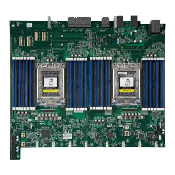
• If you have any questions, please contact our support team at: support@supermicro.com This manual may be periodically updated without notice. Please check the Supermicro website for possible updates to the manual revision level. - Page 9 Chapter 1: Introduction Figure 1-1. H12DGO-6 Motherboard Image Note: All graphics shown in this manual were based upon the latest PCB revision available at the time of publication of the manual. The motherboard you received may or may not look...
- Page 10 H12DGO-6 User's Manual H12DGO-6 REV:1.01 DESIGNED IN USA BAR CODE IPMI CODE Figure 1-2. H12DGO-6 Motherboard Layout Note: Components not documented are for internal testing only.
-
Page 11: Quick Reference
JMB_E1~E3 JMB_AIOM M.2-C2 JTPM1 LED1 M.2-C1 JBT1 CPU2 CPU1 P1-DIMMA1~D2 P2-DIMMA1~D2 P2-DIMME1~H2 P1-DIMME1~H2 JUSB1 JHDD_PWR1 FANB H12DGO-6 REV:1.01 DESIGNED IN USA LEDM1 BAR CODE IPMI CODE FAN8 FAN7 FAN6 FAN5 FAN4 FAN3 FAN2 FAN1 Notes: • See Chapter 2 for detailed information on jumpers, I/O ports, and connections. -
Page 12: Quick Reference Table
C Header (for an IPMI Card) Onboard CMOS Battery Socket JSLOT1 Supermicro I/O Riser Slot (AOM-DGO-IO) JMB_AIOM Supermicro Advanced I/O Module (AIOM) Slot via AOM-438G-AIOM JMB_E1~JMB_E4 PCIe Connectors (Connect to Middle Plate BPN-GPU-438G) JMB_E5~JMB_E6 Power Connectors (Connect to Middle Plate BPN-GPU-438G) M.2-C1, M.2-C2... -
Page 13: Motherboard Features
System on Chip Expansion Slots • 16-lane PCIe 4.0 SlimSAS interface to AIOM module (AOM-438G-AIOM) to support Supermicro Advanced I/O Module (AIOM) Networking Adapters • 24-lane PCIe 4.0 SlimSAS interface to Riser Card (RSC-G-66G4) to support 1 PCIe x16 slot with PCIe x16 signal and 1 PCIe x16 slot with PCIe x8 signal •... - Page 14 H12DGO-6 User's Manual Motherboard Features Power Management • ACPI power management (S5) • Power button override mechanism • Power-on mode for AC power recovery System Health Monitoring • Onboard voltage monitoring for +3.3V, +3.3V Standby, +5V, +5V Standby, +12V, VBAT, Vcore, Vsoc, and Memory •...
- Page 15 Chapter 1: Introduction Figure 1-3. System Block Diagram Note: This is a general block diagram and may not exactly represent the features on your motherboard. See the previous pages for the actual specifications of your motherboard.
-
Page 16: Processor And Chipset Overview
7nm process architecture, and is optimized for embedded storage solutions, networking applications, or cloud-computing platforms. With support of the new microarchitecture 7nm process technology, the H12DGO-6 drastically increases system performance for a multitude of server applications. -
Page 17: System Health Monitoring
Chapter 1: Introduction 1.4 System Health Monitoring This section describes the health monitoring features of the H12DGO-6 motherboard. The motherboard has an onboard chip that supports system health monitoring. Once a voltage becomes unstable, a warning is given or an error message is sent to the screen. The user can adjust the voltage thresholds to define the sensitivity of the voltage monitor. -
Page 18: Acpi Features
H12DGO-6 User's Manual 1.5 ACPI Features ACPI stands for Advanced Configuration and Power Interface. The ACPI specification defines a flexible and abstract hardware interface that provides a standard way to integrate power management features throughout a computer system including its hardware, operating system and application software. -
Page 19: Chapter 2 Installation
Chapter 2: Installation Chapter 2 Installation 2.1 Static-Sensitive Devices Electrostatic Discharge (ESD) can damage electronic com ponents. To prevent damage to your motherboard, it is important to handle it very carefully. The following measures are generally sufficient to protect your equipment from ESD. Precautions •... -
Page 20: Motherboard Installation
H12DGO-6 User's Manual 2.2 Motherboard Installation All motherboards have standard mounting holes to fit different types of chassis. Make sure that the locations of all the mounting holes for both the motherboard and the chassis match. Although a chassis may have both plastic and metal mounting fasteners, metal ones are highly recommended because they ground the motherboard to the chassis. - Page 21 Chapter 2: Installation Figure 2-1. Motherboard Mounting Holes...
-
Page 22: Installing The Motherboard
H12DGO-6 User's Manual Installing the Motherboard Note: Always connect the power cord last, and always remove it before adding, removing, or changing any hardware components. Install the I/O shield into the chassis. 1. Locate the mounting holes on the motherboard. See the previous page for the location. -
Page 23: Processor And Heatsink Installation
CPU socket cap is in place and none of the socket pins are bent; otherwise, contact your retailer immediately. • Refer to the Supermicro website for updates on CPU support. Installing the Processor and Heatsink 1. Unscrew the screws holding down Force Frame in the sequence of 3-2-1. The screws are numbered on the Force Frame next to each screw hole. - Page 24 H12DGO-6 User's Manual 2. The spring-loaded Force Frame will raise up after the last screw securing it (#1) is removed. Gently allow it to lift up to its stopping position. 3. Lift the Rail Frame up by gripping the lift tabs near the front end of the rail frame. While keeping a secure grip of the Rail Frame, lift it to a position so you can do the next step of removing the External Cap.
- Page 25 Chapter 2: Installation 5. Remove the External Cap from the Rail Frame by pulling it upwards through the rail guides on the Rail Frame. External Cap PnP Cover Cap 6. The CPU Package is shipped from the factory with the Carrier Frame pre-assembled. Grip the handle of the Carrier Frame/CPU Package assembly from its shipping tray, and while gripping the handle, align the flanges of the Carrier Frame onto the rails of the Rail Frame so its pins will be at the bottom when the Rail Frame is lowered later.
- Page 26 H12DGO-6 User's Manual Note: You can only install the CPU inside the socket in one direction with the handle at the top. Make sure that it is properly inserted into the CPU socket before closing the Rail Frame plate. If it doesn't close properly, do not force it as it may damage your CPU. Instead, open the Rail Frame plate again, and double-check that the CPU is aligned properly.
- Page 27 Chapter 2: Installation 9. Gently lower the Rail Frame down onto the socket until the latches on the Rail Frame engage with the Socket housing. and it rests in place. DO NOT force it into place!
- Page 28 H12DGO-6 User's Manual 10. Gently lower the Force Frame down onto the Rail Frame and hold it in place until it is seated in the Socket housing. Note that the Force Frame is spring loaded and has to be held in place before it is secured. Important: Use a torque screwdriver, set it at 16.1 kgf-cm (14.0 lbf-in) with a Torx T20 screw head bit, to prevent damage to the CPU.
- Page 29 Chapter 2: Installation 12. After the Force Frame is secured and the CPU package is in place, now you must install the heatsink to the frame. Lower the heatsink down till it rests securely over the four screw holes on CPU Package on the socket frame. 13.
- Page 30 H12DGO-6 User's Manual Un-installing the Processor and Heatsink 1. Remove the heatsink attached to the top of the CPU Package by reversing the installation procedure. 2. Clean the Thermal grease left by the heatsink on the CPU package lid to limit the risk of it contaminating the CPU package land pads or contacts in the socket housing.
-
Page 31: Memory Support And Installation
Important: Exercise extreme care when installing or removing DIMM modules to prevent any possible damage. Memory Support The H12DGO-6 supports up to 8TB of ECC DDR4 3200 MHz speed, RDIMM/LRDIMM/3DS/ NVDIMM memory in thirty-two (32) slots. Refer to the table below for additional memory information. -
Page 32: Dimm Module Population Sequence
H12DGO-6 User's Manual DIMM Module Population Sequence When installing memory modules, the DIMM slots should be populated in the following order: DIMMA2, DIMMB2, DIMMC2, DIMMD2, DIMME2, DIMMF2, DIMMG2, DIMMH2, then DIMMA1, DIMMB1, DIMMC1, DIMMD1, DIMME1, DIMMF1, DIMMG1, DIMMH1. • The blue slots must be populated first. -
Page 33: Dimm Installation
Chapter 2: Installation DIMM Installation 1. Insert the desired number of DIMMs into the memory slots, starting with DIMMA2, DIMMB2, DIMMC2, DIMMD2, DIMME2, DIMMF2, DIMMG2, DIMMH2, then DIMMA1, DIMMB1, DIMMC1, DIMMD1, DIMME1, DIMMF1, DIMMG1, DIMMH1. For best performance, please use the memory modules of the same type and speed. -
Page 34: Connectors
Trusted Platform Module Header Pin Definitions Pin# Definition Pin# Definition LCLK LFRAME# LRESET# LAD3 LAD2 3.3V LAD1 LAD0 3.3V_STBY SERIRQ SATA Ports The H12DGO-6 supports four SATA 3.0 ports through CN9 port and HDD backplane board BPN-NVMe4-F418-B6S6 with a specific cable. - Page 35 Chapter 2: Installation NVM Express Connections Two NVM Express ports are located on the serverboard (from CPU2). These ports provide high-speed, low-latency PCIe 4.0 x4 connections directly from the CPU to NVMe Solid State Drives (SSD). This greatly increases SSD data-throughput performance and significantly reduces PCIe latency by simplifying driver/software requirements resulted from direct PCIe interface from the CPU to the NVMe SSD drives.
-
Page 36: Jumper Settings
H12DGO-6 User's Manual 2.6 Jumper Settings How Jumpers Work To modify the operation of the motherboard, jumpers can be used to choose between optional settings. Jumpers create shorts between two pins to change the function of the connector. Pin 1 is identified with a square solder pad on the printed circuit board. See the diagram below for an example of jumping pins 1 and 2. - Page 37 Chapter 2: Installation Watch Dog JWD1 controls the Watch Dog function. Watch Dog is a monitor that can reboot the system when a software application hangs. Jumping pins 1-2 will cause Watch Dog to reset the system if an application hangs. Jumping pins 2-3 will generate a non-maskable interrupt (NMI) signal for the application that hangs.
-
Page 38: Led Indicators
H12DGO-6 User's Manual 2.7 LED Indicators LAN Port LEDs The IPMI Ethernet port has two LED indicators. The Activity LED is yellow and indicates connection and activity. The Link LED may be green, amber, or off to indicate the speed of the connection. -
Page 39: Chapter 3 Troubleshooting
Chapter 3: Troubleshooting Chapter 3 Troubleshooting 3.1 Troubleshooting Procedures Use the following procedures to troubleshoot your system. If you have followed all of the procedures below and still need assistance, refer to the ‘Technical Support Procedures’ and/ or ‘Returning Merchandise for Service’ section(s) in this chapter. Always disconnect the AC power cord before adding, changing or installing any non hot-swap hardware components. -
Page 40: No Video
H12DGO-6 User's Manual 5. The CMOS battery on your motherboard may be old. Check to verify that it still supplies ~3V DC. If it does not, replace it with a new one. No Video 1. Check that the VGA cable is connected properly, and the monitor is on. -
Page 41: What To Do If The System Is Losing The Setup Configuration
2. Memory support: Make sure that the memory modules are supported by testing the modules using memtest86 or a similar utility. Note: Refer to the product page on our website at http://www.supermicro.com memory and CPU support and updates. 3. HDD support: Make sure that all hard disk drives (HDDs) work properly. Replace the bad HDDs with good ones. -
Page 42: Technical Support Procedures
H12DGO-6 User's Manual with a CPU and a memory module installed) to identify the trouble areas. Refer to the steps listed in Section A above for proper troubleshooting procedures. 4. Identifying bad components by isolating them: If necessary, remove a component in question from the chassis, and test it in isolation to make sure that it works properly. -
Page 43: Frequently Asked Questions
3.3 Frequently Asked Questions Question: What type of memory does my motherboard support? Answer: The H12DGO-6 motherboard supports up to 8TB of ECC DDR4 3200 MHz speed, RDIMM/LRDIMM/3DS/NVDIMM memory in thirty-two (32) slots. See Section 2.4 for details on installing memory. - Page 44 H12DGO-6 User's Manual Question: For the AMD EPYC platform, we found that the Windows Server 2012/2016 OS would not install properly. It however works fine with Linux OS, any suggestions? Answer: This issue is due to Windows server OS' compatibility with the virtualization function, we suggest to disable IOMMU (Input/Output Memory Management Unit) before installing the Windows Server OS.
- Page 45 Chapter 3: Troubleshooting Question: Why did I fail to install Windows Server 2019 on a system with more than 255 logical processors? Answer: Follow the steps to solve the problem. 1. Disable SMT in BIOS. (BIOS >> Advanced >> CPU Configuration >> SMT Control >> Disabled) 2.
- Page 46 H12DGO-6 User's Manual Question: When I ran the executable file setup.exe to install the AMD SP3 I/O driver on Windows, the following message appeared: Answer: It happens in some environments. To solve this problem, click OK and save the installation package to the location you specify. The driver is then installed automatically.
-
Page 47: Returning Merchandise For Service
Shipping and handling charges will be applied for all orders that must be mailed when service is complete. For faster service, RMA authorizations may be requested online (http://www.supermicro.com/ support/rma/). This warranty only covers normal consumer use and does not cover damages incurred in shipping or from failure due to the alteration, misuse, abuse or improper maintenance of products. -
Page 48: Battery Installation
H12DGO-6 User's Manual Battery Installation 1. To install an onboard battery, follow the steps 1 & 2 above and continue below: 2. Identify the battery's polarity. The positive (+) side should be facing up. 3. Insert the battery into the battery holder and push it down until you hear a click to ensure that the battery is securely locked. -
Page 49: Chapter 4 Uefi Bios
UEFI BIOS 4.1 Introduction This chapter describes the AMIBIOS™ setup utility for the H12DGO-6 motherboard. The BIOS is stored on a chip and can be easily upgraded using a flash program. Note: Due to periodic changes to the BIOS, some settings may have been added or deleted and might not yet be recorded in this manual. -
Page 50: Main Setup
H12DGO-6 User's Manual 4.2 Main Setup When you first enter the AMI BIOS setup utility, you will see the Main setup screen. You can always return to the Main setup screen by selecting the Main tab on the top of the screen. - Page 51 Chapter 4: UEFI BIOS Build Date This feature displays the date when the version of the BIOS ROM used in the system was built. CPLD Version This feature displays the version of the CPLD (Complex-Programmable Logical Device) used in the system. Memory Information Total Memory This feature displays the total size of memory available in the system.
-
Page 52: Advanced
H12DGO-6 User's Manual 4.3 Advanced Warning: Take caution when changing the Advanced settings. An incorrect value, a very high DRAM frequency, or an incorrect DRAM timing setting may make the system unstable. When this occurs, revert to the default to the manufacture default settings. - Page 53 Chapter 4: UEFI BIOS Bootup NumLock State Use this feature to set the Power on state for the <Numlock> key. The options are On and Off. Wait For "F1" If Error Use this feature to force the system to wait until the 'F1' key is pressed if an error occurs. The options are Disabled and Enabled.
- Page 54 H12DGO-6 User's Manual Trusted Computing Configuration Security Device Support If this feature and the TPM jumper on the motherboard are both set to Enabled, onboard security devices will be enabled for TPM (Trusted Platform Module) support to enhance data integrity and network security. Please reboot the system for a change on this setting to take effect.
- Page 55 Chapter 4: UEFI BIOS ACPI SRAT L3 Cache As NUMA Domain Use this setting to enabe/disable ACPI SRAT L3 Cache As NUMA Domain. The options are Disabled, Enabled and Auto. Super IO Configuration The following Super IO information will display: Super IO Chip AST2600 Serial Port 1 Configuration...
- Page 56 H12DGO-6 User's Manual Serial Port 2 Attribute The options are SOL and COM. Serial Port Console Redirection COM1 Console Redirection Select Enabled to enable console redirection support for a serial port specified by the user. The options are Disabled and Enabled.
- Page 57 Chapter 4: UEFI BIOS Stop Bits A stop bit indicates the end of a serial data packet. Select 1 Stop Bit for standard serial data communication. Select 2 Stop Bits if slower devices are used. The options are 1 and 2. Flow Control Use this feature to set the flow control for Console Redirection to prevent data loss caused by buffer overflow.
- Page 58 H12DGO-6 User's Manual Console Redirection Select Enabled to enable SOL console redirection support for a serial port specified by the user. The options are Disabled and Enabled. *If the item above set to Enabled, the following items will become available for user's configuration: Console Redirection Settings...
- Page 59 Chapter 4: UEFI BIOS is full. Send a "Start" signal to start sending data when the receiving buffer is empty. The options are None and Hardware RTS/CTS. VT-UTF8 Combo Key Support Select Enabled to enable VT-UTF8 Combination Key support for ANSI/VT100 terminals. The options are Disabled and Enabled.
- Page 60 H12DGO-6 User's Manual Legacy Console Redirection Settings Legacy Serial Redirection Port For this setting, select a COM port to display redirection of Legacy OS and Legacy OPROM messages. Options include COM1 and SOL. Serial Port for Out-of-Band Management/Windows Emergency Management...
- Page 61 Chapter 4: UEFI BIOS is full. Send a "Start" signal to start sending data when the receiving buffer is empty. The options are None, Hardware RTS/CTS, and Software Xon/Xoff. Data Bits Use this feature to set the data transmission size for Console Redirection. The options are 7 and 8.
- Page 62 H12DGO-6 User's Manual Core Control This sets the number of cores to be used by your system. Once this option has been used to remove any cores, a power cycle is required in order for the future selections to take effect.
- Page 63 Chapter 4: UEFI BIOS cTDP Control Use this setting to configure the cTDP Control. Options include Manual and Auto. IOMMU Use this setting to enable/disable IOMMU. Options include Disabled, Enabled, and Auto. ACS Enable Use this setting to enable/disable ACS. Options include Enabled, Disabled and Auto. Package Power Limit Control Use this setting for Package Power Limit Control.
- Page 64 H12DGO-6 User's Manual DRAM Scrub Time This setting provides a value that is the number of hours to scrub memory. The options are Disabled, 1 hour, 4 hours, 8 hours, 16 hours, 24 hours, 48 hours and Auto. CPU1 Memory Configuration These sections are for informational purposes.
- Page 65 Chapter 4: UEFI BIOS PCIe/PCI/PnP Configuration This menu provides PCIe/PCI/PnP configuration settings and information. PCI Bus Driver Version PCI Devices Common Settings: Above 4G Decoding This setting Disables or Enables 64-bit capable devices ability to be decoded in above 4G address space (only if the system supports 64-bit PCI decoding).
- Page 66 H12DGO-6 User's Manual SLOT2 PCI-E 4.0 x16 OPROM This setting enables or disables the listed PCI/PCIX/PCIe Slot OPROM option. The options include Disabled, Legacy and EFI. SLOT3 PCI-E 4.0 x16 OPROM This setting enables or disables the listed PCI/PCIX/PCIe Slot OPROM option. The options include Disabled, Legacy and EFI.
- Page 67 Chapter 4: UEFI BIOS Onboard NVMe4 Option ROM Select EFI to allow the user to boot the computer using an EFI (Extensible Firmware Interface) device installed on the NVME connector specified by the user. Select Legacy to allow the user to boot the computer using a legacy device installed on the NVME connector specified by the user.
- Page 68 H12DGO-6 User's Manual IPv6 HTTP Support This setting allows you to enable or disable IPv6 HTTP boot support. If disabled, IPv6 HTTP boot support will not be available. The options are Disabled and Enabled. PXE boot wait time This setting allows you to set in a number field the wait time to press <ESC> to abort the PXE boot.
- Page 69 Chapter 4: UEFI BIOS SATA Hotplug This setting enables or disables the on chip SATA hot plug feature. The options are Disabled, and Enabled. SATA Information This section displays information on the detected SATA devices: • SATA0 ~ SATA3 KMIP Server Configuration KMIP Server IP address KMIP TCP Port number TimeZone...
- Page 70 H12DGO-6 User's Manual Network Configuration MAC: B03FAF2B6059F - IPv4 Network Configuration Confiured The opitons include Disabled and Enabled. *If the item above is set to Enabled, the following item will become available for configuration: Enable DHCP This feature allows the user to select the source of the IP address for this computer. If Disabled is selected, you will need to know the local IP address of this computer and enter it to the system manually in the field.
- Page 71 Chapter 4: UEFI BIOS VLAN Configuration (MAC: ACIF6BBB6FB0) Use this item to save the changes above and exit. VLAN Configuration (MAC: ACIF6BBB6FB1) Enter Configuration Menu Create new VLAN VLAN ID This option is an input field used to enter a unique numeric VLAN ID. The valid range is from 0~4096.
- Page 72 H12DGO-6 User's Manual *If the item above is set to Disabled, the following items will become available for configuration: Local IP Address This item sets and displays the Local IP address for this computer. This should be in decimal and in dotted quad form.
- Page 73 Chapter 4: UEFI BIOS Save Changes and Exit Use this item to save the changes above and exit.
-
Page 74: Ipmi
H12DGO-6 User's Manual 4.4 IPMI Use this feature to configure Event Log settings. System Event Log SEL Components Select Enabled for all system event logging at bootup. The options include Disabled and Enabled. Erashing Settings Erase SEL Select Yes, On next reset to erase all system event logs upon next system reboot. Select Yes, On every reset to erase all system event logs upon each system reboot. - Page 75 Chapter 4: UEFI BIOS When SEL is Full This feature allows the user to decide what the BIOS should do when the system event log is full. Select Erase Immediately to erase all events in the log when the system event log is full.
-
Page 76: Event Logs
H12DGO-6 User's Manual 4.5 Event Logs Use this feature to configure Event Log settings. Note: After you've made a change on a setting below, please be sure to reboot the system for the change to take effect. Change SMBIOS Event Log Settings... - Page 77 Chapter 4: UEFI BIOS Erasing Settings Erase Event Log Select No to keep the event log without erasing it upon next system bootup. Select Yes, Next Reset to erase the event log upon next system reboot. The options are No, Yes, Next reset, and Yes, Every eset.
-
Page 78: Security Settings
H12DGO-6 User's Manual 4.6 Security Settings This menu allows the user to configure the following security settings for the system. Administrator Password Use this feature to set the administrator password which is required to enter the BIOS setup utility. The length of the password should be from 3 characters to 20 characters long. - Page 79 Chapter 4: UEFI BIOS • Sucre Boot Secure Boot Select Enabled to use Secure Boot settings. The options are Disabled and Enabled. Secure Boot Mode Use this feature to select the desired secure boot mode for the system. The options are Standard and Custom.
- Page 80 H12DGO-6 User's Manual Device Guard Ready Remove 'UEFI CA' from DB Select Yes to remove UEFI CA from the database. The options are Yes and No. Restore DB defaults Select Yes to restore database variables to the manufacturer default settings. The options are Yes and No.
- Page 81 Chapter 4: UEFI BIOS of the forbidden signatures. Select Update to update your "Forbidden Signatures". Select Append to append your "Forbidden Signatures". The settings are Update, and Append. Authorized TimeStamps This feature allows the user to set and save the timestamps for the authorized signatures which will indicate the time when these signatures are entered into the system.
-
Page 82: Boot Settings
H12DGO-6 User's Manual 4.7 Boot Settings Use this feature to configure Boot Settings: Boot Mode Select Use this feature to select the type of devices from which the system will boot. The options are Legacy, UEFI (Unified Extensible Firmware Interface), and Dual. - Page 83 Chapter 4: UEFI BIOS When the item above -"Boot Mode Select" is set to Legacy, the following items will be displayed for configuration: • Boot Option #1 - Boot Option #8 When the item above -"Boot Mode Select" is set to UEFI, the following items will be displayed for configuration: •...
-
Page 84: Save & Exit
H12DGO-6 User's Manual 4.8 Save & Exit Select the Save & Exit menu from the BIOS setup screen to configure the settings below. Save Options Discard Changes and Exit Select this option to exit from the BIOS setup utility without making any permanent changes to the system configuration and reboot the computer. - Page 85 Chapter 4: UEFI BIOS Discard Changes Select this option and press <Enter> to discard all the changes you've made and return to the AMI BIOS setup utility. Default Options Restore Optimized Defaults To set this feature, select Restore Defaults from the Exit menu and press <Enter> to load manufacturer default settings which are intended for maximum system performance but not for maximum stability.
-
Page 86: Appendix A Software
USB/SATA DVD drive, or a USB flash drive, or the IPMI KVM console. 2. Retrieve the proper RST/RSTe driver. Go to the Supermicro web page for your motherboard and click on "Download the Latest Drivers and Utilities", select the proper driver, and copy it to a USB flash drive. - Page 87 Appendix A: Software 4. During Windows Setup, continue to the dialog where you select the drives on which to install Windows. If the disk you want to use is not listed, click on “Load driver” link at the bottom left corner. Figure A-2.
-
Page 88: Driver Installation
The Supermicro website contains drivers and utilities for your system at https://www. supermicro.com/wftp/driver. Some of these must be installed, such as the chipset driver. After accessing the website, go into the CDR_Images (in the parent directory of the above link) and locate the ISO file for your motherboard. Download this file to to a USB flash drive or a DVD. -
Page 89: Superdoctor ® 5
A.3 SuperDoctor ® The Supermicro SuperDoctor 5 is a program that functions in a command-line or web-based interface for Windows and Linux operating systems. The program monitors such system health information as CPU temperature, system voltages, system power consumption, fan speed, and provides alerts via email or Simple Network Management Protocol (SNMP). -
Page 90: Appendix B Standardized Warning Statements
The following statements are industry standard warnings, provided to warn the user of situations which have the potential for bodily injury. Should you have questions or experience difficulty, contact Supermicro's Technical Support department for assistance. Only certified technicians should attempt to install or configure components. - Page 91 Appendix B: Warning Statements Attention Danger d'explosion si la pile n'est pas remplacée correctement. Ne la remplacer que par une pile de type semblable ou équivalent, recommandée par le fabricant. Jeter les piles usagées conformément aux instructions du fabricant. ¡Advertencia! Existe peligro de explosión si la batería se reemplaza de manera incorrecta.
-
Page 92: Product Disposal
H12DGO-6 User's Manual B.2 Product Disposal Warning! Ultimate disposal of this product should be handled according to all national laws and regulations. 製品の廃棄 この製品を廃棄処分する場合、 国の関係する全ての法律 ・ 条例に従い処理する必要があります。 警告 本产品的废弃处理应根据所有国家的法律和规章进行。 警告 本產品的廢棄處理應根據所有國家的法律和規章進行。 Warnung Die Entsorgung dieses Produkts sollte gemäß allen Bestimmungen und Gesetzen des Landes erfolgen. -
Page 93: Appendix C Uefi Bios Recovery
Warning: Do not upgrade the BIOS unless your system has a BIOS-related issue. Flashing the wrong BIOS can cause irreparable damage to the system. In no event shall Supermicro be liable for direct, indirect, special, incidental, or consequential damages arising from a BIOS update. - Page 94 H12DGO-6 User's Manual Note: If you cannot locate the "SUPER.ROM" file in your driver disk, visit our website at www. supermicro.com to download the correct BIOS image into a USB flash device and rename it "SUPER.ROM". 1. While the system is turned off, insert the USB device that contains the new BIOS binary image (SUPER.ROM).
- Page 95 SUPERMICO BIOS Update: https://www.youtube.com/watch?v=S8z6iOEHGwY • * If the BIOS flash recovery fails, contact our RMA Department to have the BIOS chip reprogrammed. This will require shipping the board to Supermicro for repair. • Submit your RMA request at https://www.supermicro.com/support/rma •...
Need help?
Do you have a question about the H12DGO-6 and is the answer not in the manual?
Questions and answers