Table of Contents
Advertisement
Quick Links
Advertisement
Table of Contents

Related Manuals for Supermicro H13DSG-OM


Summary of Contents for Supermicro H13DSG-OM
- Page 1 H13DSG-OM USER’S MANUAL Revision 1.0...
- Page 2 State of California, USA. The State of California, County of Santa Clara shall be the exclusive venue for the resolution of any such disputes. Supermicro's total liability for all claims will not exceed the price paid for the hardware product.
- Page 3 About This Manual This manual is written for system integrators, IT technicians and knowledgeable end users. It provides information for the installation and use of the H13DSG-OM motherboard. About This Motherboard Built upon the functionality and capability of the Dual AMD EPYC...
-
Page 4: Contacting Supermicro
H13DSG-OM User's Manual Contacting Supermicro Headquarters Address: Super Micro Computer, Inc. 980 Rock Ave. San Jose, CA 95131 U.S.A. Tel: +1 (408) 503-8000 Fax: +1 (408) 503-8008 Email: marketing@supermicro.com (General Information) Sales-USA@supermicro.com (Sales Inquiries) Government_Sales-USA@supermicro.com (Gov. Sales Inquiries) support@supermicro.com (Technical Support) RMA@supermicro.com (RMA Support) -
Page 5: Table Of Contents
Contents Table of Contents Contacting Supermicro ......................4 Chapter 1 Introduction 1.1 Quick Reference .........................10 Quick Reference Table ......................11 Motherboard Features .......................13 Block Diagram ........................15 1.2 Processor and Chipset Overview ..................16 Recovery from AC Power Loss ............16 1.4 System Health Monitoring ....................16 Onboard Voltage Monitors ....................16... - Page 6 Contents Headers ..........................36 2.6 Jumper Settings .........................37 How Jumpers Work ......................37 2.7 LED Indicators ........................38 2.8 M.2 Solid State Drive Installation ..................39 Chapter 3 Troubleshooting 3.1 Troubleshooting Procedures ....................40 Before Power On ......................40 No Power ..........................40 No Video ...........................41 System Boot Failure ......................41 Memory Errors ........................41 What to Do If the System Is Losing the Setup Configuration...........41 When the System Becomes Unstable ................42...
-
Page 7: Chapter 1 Introduction
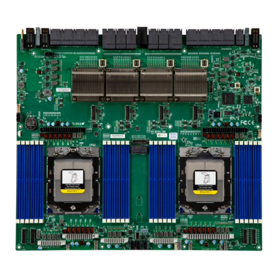
A secure data deletion tool designed to fully erase all data from storage devices can be found at our website: https://www.supermicro.com/about/policies/disclaimer.cfm?url=/ wdl/ utility/Lot9_Secure_Data_Deletion_Utility • If you have any questions, contact our support team at: support@supermicro.com This manual may be periodically updated without notice. Check the Supermicro website for possible updates to the manual revision level. - Page 8 Chapter 1: Introduction Figure 1-1. H13DSG-OM Motherboard Image Note: All graphics shown in this manual were based upon the latest PCB revision available at the time of publication of the manual. The motherboard you received may or may not look...
-
Page 9: Quick Reference
BAR CODE LED2 BAR CODE BAR CODE LED1 JNVME4 JNVME3 JNVME2 JNVME1 JRSC0 JTPM1 JPG1 JPWR2 JPWR1 JPFR2 JPFR3 JRSI2C1 H13DSG-OM JRSC1 JI01 BIOS LICENSE BAR CODE BAR CODE CPU2 CPU1 P2-DIMMA1 P1-DIMML1 P2-DIMMB1 P2-DIMMK1 P2-DIMMC1 P2-DIMMJ1 P2-DIMMD1 P2-DIMMI1 P2-DIMME1... -
Page 10: Quick Reference Table
Chapter 1: Introduction Quick Reference Table Jumper Description Default Setting JPFR1 PFR Function Open (Normal) JPFR2 PFR Function Open (Normal) JPFR3 PFR Function Open (Normal) JPG1 VGA Enable/Disable Pins 1-2 (Enable) JUID1 Switch function UID/Reset Pins 1-2 (UID) Description Status LED1 Power LED Solid Green: Power On... - Page 11 Chapter 1: Introduction Note: Jumpers, connectors, switches, and LED indicators that are not described in the preceding tables are for manufacturing testing purposes only, and are not covered in this manual.
-
Page 12: Motherboard Features
Chapter 1: Introduction Motherboard Features • Dual AMD EPYC 9004 series processors in SP5 sockets Memory • Up to 6 TB registered ECC DDR5 4800 MT/s speed in twenty-four slots DIMM Size • Up to 256 GB Chipset • System on Chip (SoC) Expansion Slots •... - Page 13 Chapter 1: Introduction System Management • IPMIView/SMCIPMITOOL/IPMICFG • SuperDoctor® 5 • SDO/SPM/SSM/SUM-OOB/InBand • Trusted Platform Module (TPM) support LED Indicators • CPU / System Overheating • Power / Suspend-state Indicator • Fan Failure Dimensions • 16.7" (W) x 15" (L), (424.18 mm x 381 mm) Note: The CPU maximum thermal design power (TDP) is subject to chassis and heatsink cooling restrictions.
-
Page 14: Block Diagram
Chapter 1: Introduction Block Diagram Backplane 8 x PCIe 5.0 x16 RETIMER PCIE Riser 32.0 GT/s 8 x PCIe 5.0 x16 32.0 GT/s Mellanox NIC 8 x GPU USB2.0 480Mbit/s PEG P5C PCIe 3.0 x2 PCIe 3.0 x1 PEG P5D PEG P5D 8.0 GT/s 8.0 GT/s... -
Page 15: Processor And Chipset Overview
The default setting is Last State. 1.4 System Health Monitoring This section describes the health monitoring features of the H13DSG-OM motherboard. The motherboard has an onboard Baseboard Management Controller (BMC) chip that supports system health monitoring. Once a voltage becomes unstable, a warning is given or an error message is sent to the screen. -
Page 16: Fan Status Monitor With Firmware Control
Chapter 1: Introduction Fan Status Monitor with Firmware Control PC health monitoring in the BIOS can check the RPM status of the cooling fans. The onboard CPU and chassis fans are controlled by Thermal Management. Environmental Temperature Control The thermal control sensor monitors the CPU temperature in real time and will turn on the thermal control fan whenever the CPU temperature exceeds a user-defined threshold. -
Page 17: Power Supply
Chapter 1: Introduction 1.6 Power Supply As with all computer products, a stable power source is necessary for proper and reliable operation. It is even more important for processors that have high CPU clock rates. In areas where noisy power transmission is present, you may choose to install a line filter to shield the computer from noise. -
Page 18: Chapter 2 Installation
Chapter 2: Installation Chapter 2 Installation 2.1 Static-Sensitive Devices Electrostatic Discharge (ESD) can damage electronic com ponents. To prevent damage to your motherboard, it is important to handle it very carefully. The following measures are generally sufficient to protect your equipment from ESD. Precautions •... -
Page 19: Motherboard Installation
Chapter 2: Installation 2.2 Motherboard Installation All motherboards have standard mounting holes to fit different types of chassis. Make sure that the locations of all the mounting holes for both the motherboard and the chassis match. Although a chassis may have both plastic and metal mounting fasteners, metal ones are highly recommended because they ground the motherboard to the chassis. - Page 20 Chapter 2: Installation Figure 2-1. Motherboard Mounting Holes...
-
Page 21: Installing The Motherboard
Chapter 2: Installation Installing the Motherboard Note: Always connect the power cord last, and always remove it before adding, removing, or changing any hardware components. Install the I/O shield into the chassis. 1. Install the I/O shield into the back of the chassis. 2. -
Page 22: Processor And Heatsink Installation
CPU socket cap is in place and none of the socket pins are bent; otherwise, contact your retailer immediately. • Refer to the Supermicro website for updates on CPU support. Installing the Processor and Heatsink 1. Unscrew the screw #1 holding down the force frame. - Page 23 Chapter 2: Installation 2. The spring-loaded force frame will raise up after the screw securing it (#1) is removed. Gently allow it to lift up to its stopping position. Force Frame 3. Lift the rail frame up by gripping the lift tabs near the front end of the rail frame. While keeping a secure grip of the rail frame, lift it to a position so you can do the next step of removing the external cap.
- Page 24 Chapter 2: Installation 4. Remove the external cap from the rail frame by pulling it upwards through the rail guides on the rail frame. External Cap 5. The CPU package is shipped from the factory with the carrier frame pre-assembled. Grip the handle of the carrier frame/CPU package assembly from its shipping tray, and while gripping the handle, align the flanges of the carrier frame onto the rails of the rail frame so its pins will be at the bottom when the rail frame is lowered later.
- Page 25 Chapter 2: Installation Note: You can only install the CPU inside the socket in one direction with the handle at the top. Make sure that it is properly inserted into the CPU socket before closing the rail frame plate. If it doesn't close properly, do not force it as it may damage your CPU. Instead, open the rail frame plate again, and double-check that the CPU is aligned properly.
- Page 26 Chapter 2: Installation 8. Gently lower the rail frame down onto the socket until the latches on the rail frame engage with the socket housing and it rests in place. DO NOT force it into place! 9. The force frame is spring loaded and has to be held in place before it is secured. Important: Use a torque screwdriver, set it at 12.5~15.0 kgfcm (10.85~13.01 lbf-in) with a Torx T20 screw head bit, to prevent damage to the CPU.
- Page 27 Chapter 2: Installation 10. Place and re-screw the screw in the middle to the way you removed it. When finished, the force frame will be secure over both the rail frame and CPU package. 11. After the force frame is secured and the CPU package is in place, now you must install the heatsink to the frame.
- Page 28 Chapter 2: Installation 12. Using a diagonal pattern, tighten the six screws down on the heatsink in a clockwise fashion till it is secure. The heatsink will now be secured and you have finished installing the processor and heatsink onto the motherboard. Repeat this procedure for any remaining CPU sockets on the motherboard.
- Page 29 Chapter 2: Installation Un-installing the Processor and Heatsink 1. Remove the heatsink attached to the top of the CPU package by reversing the installation procedure. 2. Clean the thermal grease left by the heatsink on the CPU package lid to limit the risk of it contaminating the CPU package landing pads and contacts in the socket housing.
-
Page 30: Memory Support And Installation
Important: Exercise extreme care when installing or removing DIMM modules to prevent any possible damage. Memory Support The H13DSG-OM supports up to 6 TB of ECC DDR5 4800 MT/s speed, RDIMM/3DS memory in 24 slots. Refer to the table below for additional memory information. DIMM Population Guide... - Page 31 Chapter 2: Installation Populating RDIMM / 3DS DDR5 Memory Modules with AMD EPYC 9004 series Processor DIMM Population Maximum DIMM Capacity Type Maximum Frequency (MT/s) DIMM1 1 Channel 12 Channels 1R (1 rank) 32 GB 384 GB 4800 RDIMM 2R (2 ranks) 64 GB 768 GB 4800...
-
Page 32: Dimm Module Population Guide
Chapter 2: Installation DIMM Module Population Guide There is no specific order or sequence required when installing memory modules. However do keep the following in mind: • Always use DDR5 DIMM modules of the same type, size, and speed. • All twelve channels should be populated with the same capacity to achieve the best per- formance in most cases. -
Page 33: Dimm Installation
Chapter 2: Installation DIMM Installation 1. Insert the desired number of DIMMs into the memory slots, see DIMM Module Population Guide for details. 2. Push the release tabs outwards on both ends of the DIMM slot to unlock it. Receptive Point 3. -
Page 34: Connectors
+54 V Ground +54 V Ground +54 V Power Supply Connectors JSW_PWR1, JSW_PWR2 and JSW_PWR4 are the 12 V power sources for the H13DSG-OM motherboard. SATA Port The H13DSG-OM has one SATA 3.0 port (JS1) that is supported by ASMEDIA ASM1061. -
Page 35: Headers
Port 80 connection. Use this header to enhance system performance and data security. Refer to the table below for pin definitions. For more information on the TPM, go to the following link: http://www.supermicro.com/manuals/other/TPM.pdf. Trusted Platform Module Header Pin Definitions... -
Page 36: Jumper Settings
Chapter 2: Installation 2.6 Jumper Settings How Jumpers Work To modify the operation of the motherboard, jumpers can be used to choose between optional settings. Jumpers create shorts between two pins to change the function of the connector. Pin #1 is identified with a square solder pad on the printed circuit board. See the diagram below for an example of jumping pins 1 and 2. - Page 37 Chapter 2: Installation JPG1 JPG1 enables or disables the VGA connector. The default setting is enabled. JPG1 Jumper Position Definition Pins 1-2 Enabled Pins 2-3 Disabled JUID1 JUID1 is used for a chassis that supports a front UID button. Setting JUID1 to pin 2-3 configures the front UID button as a reset button.
-
Page 38: Led Indicators
Chapter 2: Installation 2.7 LED Indicators Onboard Power LED (LED1) LED1 is an onboard power LED. When this LED is lit, it means system is in power-on state, and the onboard power status is ok. Turn off the system and unplug the power cord before removing or installing components. -
Page 39: Solid State Drive Installation
Chapter 2: Installation 2.8 M.2 Solid State Drive Installation Installing Dual M.2 SSDs 1. Disconnect power from the motherboard or system. 2. Refer to the motherboard layout and locate the M.2 dual slot (J18). 3. Insert lower M.2 sideways into the connector so that it lays flat, then follow the instructions below from 4. -
Page 40: Chapter 3 Troubleshooting
Chapter 3: Troubleshooting Chapter 3 Troubleshooting 3.1 Troubleshooting Procedures Use the following procedures to troubleshoot your system. If you have followed all of the procedures below and still need assistance, refer to the ‘Technical Support Procedures’ and/or ‘Returning Merchandise for Service’ section(s) in this chapter. Always disconnect the AC power cord before adding, changing or installing any non hot-swappable hardware components. -
Page 41: No Video
Chapter 3: Troubleshooting 5. The CMOS battery on your motherboard may be old. Check to verify that it still supplies approximately 3 VDC. If it does not, replace it with a new one. No Video 1. Check that the VGA cable is connected properly, and the monitor is on. 2. -
Page 42: When The System Becomes Unstable
2. Memory support: Make sure that the memory modules are supported by testing the modules using memtest86 or a similar utility. Note: Refer to the product page on our website at http://www.supermicro.com for memory and CPU support and updates. 3. HDD support: Make sure that all hard disk drives (HDDs) work properly. Replace the bad HDDs with good ones. -
Page 43: Technical Support Procedures
Note: Not all BIOS can be flashed depending on the modifications to the boot block code. 3. If you still cannot resolve the problem, include the following information when contacting Supermicro for technical support: • Motherboard model and PCB revision number •... -
Page 44: Frequently Asked Questions
Chapter 3: Troubleshooting 3.3 Frequently Asked Questions Question: What type of memory does my motherboard support? Answer: The H13DSG-OM motherboard supports up to 256 GB of ECC DDR5 4800 MT/s speed, RDIMM/3DS DIMM modules in twenty-four slots. See Section 2.4 for details on installing memory. -
Page 45: Returning Merchandise For Service
Shipping and handling charges will be applied for all orders that must be mailed when service is complete. For faster service, RMA authorizations may be requested online (http://www.supermicro.com/ support/rma/). This warranty only covers normal consumer use and does not cover damages incurred in shipping or from failure due to the alteration, misuse, abuse or improper maintenance of products. -
Page 46: Proper Battery Disposal
Chapter 3: Troubleshooting Proper Battery Disposal Handle used batteries carefully. Do not damage the battery in any way; a damaged battery may release hazardous materials into the environment. Do not discard a used battery in the garbage or a public landfill. Comply with the regulations set up by your local hazardous waste management agency to dispose of your used battery properly. -
Page 47: Chapter 4 Uefi Bios
UEFI BIOS 4.1 Introduction This chapter describes the AMIBIOS™ Setup utility for the H13DSG-OM motherboard. The BIOS is stored on a chip and can be easily upgraded using a flash program. Note: Due to periodic changes to the BIOS, some settings may have been added or deleted and might not yet be recorded in this manual. -
Page 48: Main Setup
Note: The time is in the 24-hour format. For example, 5:30 P.M. appears as 17:30:00. The date's default value is 01/01/2015 after RTC reset. Supermicro H13DSG-OM BIOS Version This item displays the version of the BIOS ROM used in the system. - Page 49 Chapter 4: UEFI BIOS Build Date This item displays the date when the version of the BIOS ROM used in the system was built. CPLD Version This item displays the CPLD version of the BIOS ROM used in the system. Memory Information Total Memory This item displays the total size of memory available in the system.
-
Page 50: Advanced
Chapter 4: UEFI BIOS 4.3 Advanced Use the arrow keys to select Boot Setup and press <Enter> to access the submenu items. Warning: Take caution when changing the Advanced settings. An incorrect value, a very high DRAM frequency, or an incorrect DRAM timing setting may make the system unstable. - Page 51 Chapter 4: UEFI BIOS Bootup NumLock State Use this feature to set the Power on state for the <Numlock> key. The options are On and Off. Wait For "F1" If Error Use this feature to force the system to wait until the <F1> key is pressed if an error occurs. The options are Disabled and Enabled.
- Page 52 Chapter 4: UEFI BIOS CPU Configuration CPU Configuration SMT Control Use this setting to specify Simultaneous Multithreading. The options include Disabled, Enabled and Auto. Core Performance Boost This setting is used to configure for Core Performance Boost. The options include Disabled and Auto.
- Page 53 Chapter 4: UEFI BIOS Monitor and MWAIT Disable Select Enable to support Monitor and Mwait. MWAIT instruction provides hints to allow the processor to enter an implementation-dependent optimized state The options include Enabled, Disabled and Auto. L1 Stream HW Prefetcher This setting is used to enable or disable the L1 Stream Hardware Prefetcher.
- Page 54 Chapter 4: UEFI BIOS CPU1 PCIe Package Group P2 This setting selects the PCIe port bifurcation configuration for the selected slot. The options include Auto, x4x4x4x4, x4x4x8, x8x4x4, x8x8 and x16. CPU1 PCIe Package Group G2 This setting selects the PCIe port bifurcation configuration for the selected slot. The options include Auto, x4x4x4x4, x4x4x8, x8x4x4, x8x8 and x16.
- Page 55 Chapter 4: UEFI BIOS • L1 Instruction Cache (Size/Method) • L1 Data Cache (Size/Method) • L2 Cache (Size/Method) • L3 Cache per Socket (Size/Method) CPU2 PCIe Package Group P2 This setting selects the PCIe port bifurcation configuration for the selected slot. The options include Auto, x4x4x4x4, x4x4x8, x8x4x4, x8x8 and x16.
- Page 56 Chapter 4: UEFI BIOS DMAr Support Enable DMAr system protection during POST. The options include Disabled, Enabled and Auto. DMA Protection Enable DMA remap support in IVRS IVinfo Field. The options include Auto, Enabled and Disabled. DRTM Virtual Device Support Enable DRTM ACPI virtual device.
- Page 57 Chapter 4: UEFI BIOS Periodic Training Use this setting to specify Periodic Training configuration. The options include Auto, Enabled, and Disabled. EQ Bypass To Highest Rate Use this setting to control the ability to advertise Equalization Bypass to Highest Rate Support in TSxs sent prior to LinkUp=1.
- Page 58 Chapter 4: UEFI BIOS BankSwapMode This setting controls the Bank Swap Mode. The options are Auto, Disabled and Swap CPU. Power Down Enable Use this setting to enable or disable DDR power down mode. The options are Disabled, Enabled and Auto. DRAM Scrub Time This setting provides a value that is the number of hours to scrub memory.
- Page 59 Chapter 4: UEFI BIOS Trusted Computing Configuration Security Device Support If this feature and the TPM jumper on the motherboard are both set to Enabled, onboard security devices will be enabled for TPM (Trusted Platform Module) support to enhance data integrity and network security.
- Page 60 Chapter 4: UEFI BIOS Serial Port 1 Configuration Serial Port 1 Select Enabled to enable the selected onboard serial port. The options are Disabled and Enabled. Change Settings This feature specifies the base I/O port address and the Interrupt Request address of a serial port specified by the user.
- Page 61 Chapter 4: UEFI BIOS and function key support. Select ANSI to use the Extended ASCII Character Set. Select VT-UTF8 to use UTF8 encoding to map Unicode characters into one or more bytes. The options are VT100, VT100+, VT-UTF8 and ANSI. Bits Per Second Use this feature to set the transmission speed for a serial port used in Console Redirection.
- Page 62 Chapter 4: UEFI BIOS Putty KeyPad This feature selects the settings for Function Keys and KeyPad used for Putty, which is a terminal emulator designed for the Windows OS. The options are VT100, LINUX, XTERMR6, SC0, ESCN and VT400. Console Redirection Select Enabled to enable console redirection support for a serial port specified by the user.
- Page 63 Chapter 4: UEFI BIOS Flow Control Use this feature to set the flow control for Console Redirection to prevent data loss caused by buffer overflow. Send a "Stop" signal to stop sending data when the receiving buffer is full. Send a "Start" signal to start sending data when the receiving buffer is empty. The options are None and Hardware RTS/CTS.
- Page 64 Chapter 4: UEFI BIOS Console Redirection EMS Select Enabled to enable EMS console redirection support for a serial port specified by the user. The options are Disabled and Enabled. PCIe/PCI/PnP Configuration This menu provides PCIe/PCI/PnP configuration settings and information. PCI Bus Driver Version PCI Devices Common Settings: Above 4G Decoding This setting Disables or Enables 64-bit capable devices ability to be decoded in above 4G...
- Page 65 Chapter 4: UEFI BIOS Relaxed Ordering Select Enable to enable Relaxed Ordering support, which will allow certain transactions to violate the strict-ordering rules of PCI bus for a transaction to be completed prior to other transactions that have already been enqueued. The options are Disabled and Enabled. Clock Spread Spectrum Use this setting to Disable or Enable CG1_PLL Spread Spectrum for your system.
- Page 66 Chapter 4: UEFI BIOS CPU SLOT5 PCIe 5.0 x16 OPROM This setting enables or disables PCIe SLOT5 OPROM option. The options include Disabled and EFI. CPU SLOT6 PCIe 5.0 x16 OPROM This setting enables or disables PCIe SLOT6 OPROM option. The options include Disabled and EFI.
- Page 67 Chapter 4: UEFI BIOS USB Configuration Legacy USB Support Select Enabled to support onboard legacy USB devices. Select Auto to disable legacy support if there are no legacy USB devices present. Select Disable to have all USB devices available for EFI applications only. The options are Enabled, Disabled and Auto. XHCI Hand-Off This is a work-around solution for operating systems that do not support XHCI (Extensible Host Controller Interface) hand-off.
- Page 68 Chapter 4: UEFI BIOS Media Detect Count This setting allows you set in a number field the number of times presence of media will be checked. The default value is 1. SATA Configuration This section displays the detected SATA devices installed on the system. ASMedia SATA Controller Use this setting to enable or disable the ASMedia SATA controller.
- Page 69 Supermicro KMS Server Configuration Supermicro KMS Server IP address Enter IP4 address in dotted-decimal notation. Second Supermicro KMS Server IP address Enter IP4 address in dotted-decimal notation. Supermicro KMS TCP Port number Use this feature to enter the SMCI KMS TCP port number. The valid range is 100 - 9999.
- Page 70 Chapter 4: UEFI BIOS Client Certificate For the client certificate, use this feature to enroll factory defaults or load the KMS TLS certificates from the file. The options include Update, Delete and Export. Client Private Key For the client private key, use this feature to enroll factory defaults or load the KMS TLS certificates from the file.
- Page 71 Chapter 4: UEFI BIOS Commit Changes and Exit Use this feature to save all changes and exit TLS settings. Discard Changes and Exit Use this feature to discard all changes and exit TLS settings. Delete Certification Use this feature to enable or disable the deletion of certificate. The options include Dis- abled and Enabled.
-
Page 72: Bmc
Chapter 4: UEFI BIOS 4.4 BMC This tab allows you to configure the following IPMI settings for the system. Use this feature to configure Intelligent Platform Management Interface (IPMI) settings. BMC Firmware Revision This item indicates the IPMI firmware revision used in your system. BMC Status This item indicates the status of the IPMI firmware installed in your system. - Page 73 Chapter 4: UEFI BIOS Erasing Settings Erase SEL Select Yes, On next reset to erase all system event logs upon next system reboot. Select Yes, On every reset to erase all system event logs upon each system reboot. Select No to keep all system event logs after each system reboot.
- Page 74 Chapter 4: UEFI BIOS Station MAC Address This item displays the Station MAC address for this computer. Mac addresses are 6 two-digit hexadecimal numbers. Gateway IP Address This item displays the Gateway IP address for this computer. This should be in decimal and in dotted quad form (i.e., 172.31.0.1).
-
Page 75: Event Logs
Chapter 4: UEFI BIOS 4.5 Event Logs This tab allows the user to configure the following event logs settings for the system. Change SMBIOS Event Log Settings This feature allows the user to configure SMBIOS Event settings. Enabling/Disabling The options SMBIOS Event Log Select Enabled to enable SMBIOS (System Management BIOS) Event Logging during system boot. - Page 76 Chapter 4: UEFI BIOS When Log is Full Select Erase Immediately to immediately erase all errors in the SMBIOS event log when the event log is full. Select Do Nothing for the system to do nothing when the SMBIOS event log is full. The options are Do Nothing and Erase Immediately. SMBIOS Event Log Standard Settings Log System Boot Event Select Enabled to log system boot events.
-
Page 77: Security
BIOS Setup utility. The options are Setup and Always. Supermicro Security Erase Configuration Secure Boot This section contains The options and menus for securing your boot mode and for key... - Page 78 Chapter 4: UEFI BIOS Secure Boot This option allows you specify when the Platform Key (PK) is enrolled. When enabled, the System Mode is user deployed, and the CSM function is disabled. The options include Disabled and Enabled. Secure Boot Mode Use this item to select the secure boot mode.
- Page 79 Chapter 4: UEFI BIOS Export Secure Boot Variables Use this feature to export NVRAM content of secure boot variables to files in a root folder on a file system device. Secure Boot Variable / Size / Key Numbers / Key Source Platform Key (PK) This feature allows the user to enter and configure a set of values to be used as platform firmware keys for the system.
- Page 80 Chapter 4: UEFI BIOS Select Update to update your "Authorized TimeStamps". Select Append to append your "Authorized TimeStamps". The settings are Update, and Append. OsRecovery Signature (dbr) This item uploads and installs an OSRecovery Signature. Use this feature to export NVRAM content of secure boot variables to files in a root folder on a file system device.
-
Page 81: Boot Settings
Chapter 4: UEFI BIOS 4.7 Boot Settings Use this tab to configure Boot Settings: Boot Mode Select Use this item to select the type of device that the system is going to boot from. The options are Legacy, UEFI, and DUAL. The default setting is UEFI. Legacy to EFI Support This option Disables or Enables the system to boot to an EFI OS after the boot failed from the legacy boot order. - Page 82 Chapter 4: UEFI BIOS Add New Boot Option Add boot option Use this seting to specify a name for a new boot option. Path for boot option Enter the path to the boot option in the format. Boot option File Path Create Creates the newly formed boot option.
-
Page 83: Save & Exit
Chapter 4: UEFI BIOS 4.8 Save & Exit Select the Save & Exit tab to enter the Save & Exit BIOS Setup screen. Save The options Discard Changes and Exit Select this option to quit the BIOS Setup without making any permanent changes to the system configuration, and reboot the computer. - Page 84 Chapter 4: UEFI BIOS Default The options Restore Optimized Defaults To set this feature, select Restore Defaults from the Save & Exit menu and press <Enter>. These are factory settings designed for maximum system stability, but not for maximum performance. Save as User Defaults To set this feature, select Save as User Defaults from the Exit menu and press <Enter>.
-
Page 85: Appendix A Software
1. Create a method to access the Microsoft Windows installation ISO file. That can be a USB flash or media drive. 2. Go to the Supermicro web page for your motherboard and click on "Download the Latest Drivers and Utilities", select the proper driver, and copy it to a USB flash drive. - Page 86 Appendix A: Software 4. During Windows Setup, continue to the dialog where you select the drives on which to install Windows. If the disk you want to use is not listed, click on “Load driver” link at the bottom left corner. Figure A-2.
- Page 87 The Supermicro website contains drivers and utilities for your system at https://www. supermicro.com/wdl/. Some of these must be installed, such as the chipset driver. After accessing the website, go into the CDR_Images (in the parent directory of the above link) and locate the ISO file for your motherboard.
- Page 88 Appendix A: Software A.3 SuperDoctor® 5 The Supermicro SuperDoctor 5 is a program that functions in a command-line or web-based interface for Windows and Linux operating systems. The program monitors such system health information as CPU temperature, system voltages, system power consumption, fan speed, and provides alerts via email or Simple Network Management Protocol (SNMP).
-
Page 89: Appendix B Standardized Warning Statements
The following statements are industry standard warnings, provided to warn the user of situations which have the potential for bodily injury. Should you have questions or experience difficulty, contact Supermicro's Technical Support department for assistance. Only certified technicians should attempt to install or configure components. - Page 90 Appendix B: Warning Statements Attention Danger d'explosion si la pile n'est pas remplacée correctement. Ne la remplacer que par une pile de type semblable ou équivalent, recommandée par le fabricant. Jeter les piles usagées conformément aux instructions du fabricant. ¡Advertencia! Existe peligro de explosión si la batería se reemplaza de manera incorrecta.
- Page 91 Appendix B: Warning Statements B.2 Product Disposal Warning! Ultimate disposal of this product should be handled according to all national laws and regulations. 製品の廃棄 この製品を廃棄処分する場合、 国の関係する全ての法律 ・ 条例に従い処理する必要があります。 警告 本产品的废弃处理应根据所有国家的法律和规章进行。 警告 本產品的廢棄處理應根據所有國家的法律和規章進行。 Warnung Die Entsorgung dieses Produkts sollte gemäß allen Bestimmungen und Gesetzen des Landes erfolgen.
Need help?
Do you have a question about the H13DSG-OM and is the answer not in the manual?
Questions and answers