
Related Manuals for Beckhoff CP6900-0001-0000


Summary of Contents for Beckhoff CP6900-0001-0000
- Page 1 Installation and Operating instructions for CP6900-0001-0000/ CP6906-0001-0000 “Economy” built-in Control Panel with DVI/ USB Extended interface Version: 1.3 Date: 2019-06-05...
-
Page 3: Table Of Contents
Connection Kits DVI-E/ USB-E connection for CP690x, optional 3 Installation Transport and Unpacking 3.1.1 Transport 3.1.2 Unpacking 4 Mounting Installation in the control cabinet 4.1.1 Preparation of the control cabinet 4.1.2 Installation in a control cabinet wall Mounting of the Control Panel CP6900-0001-0000/ CP6906-0001-0000... - Page 4 6 Troubleshooting 7 Assembly dimensions 8 Technical Data 9 Appendix Beckhoff Support and Service 9.1.1 Beckhoff branches and partner companies 9.1.2 Beckhoff company headquarters Approvals for USA and Canada FCC Approvals for the United States of America FCC Approval for Canada...
-
Page 5: Foreword
Modifications to hardware or software configurations other than those described in the documentation are not permitted, and nullify the liability of Beckhoff Automation GmbH & Co. KG. 1.1.6 Delivery conditions In addition, the general delivery conditions of the company Beckhoff Automation GmbH & Co. KG apply. CP6900-0001-0000/ CP6906-0001-0000... -
Page 6: Description Of Safety Symbols
CAUTION Hazard to devices and environment If you do not adhere the notice adjoining this symbol, there is obvious hazard to materials and environment. Attention Note or pointer This symbol indicates information that contributes to better understanding. Note CP6900-0001-0000/ CP6906-0001-0000... -
Page 7: Basic Safety Measures
Fitting work on the Control Panel can result in damage: • if metal objects such as screws or tools fall onto operating circuit boards • if connecting cables internal to the Panel PC are removed or inserted during operation. CP6900-0001-0000/ CP6906-0001-0000... -
Page 8: Operator's Obligation To Exercise Diligence
1.4.3 Operator requirements Anyone who uses the Control Panel must have read these operating instructions and must be familiar with all the functions of the software installed on the Industrial PC to which he has access. CP6900-0001-0000/ CP6906-0001-0000... -
Page 9: Product Description
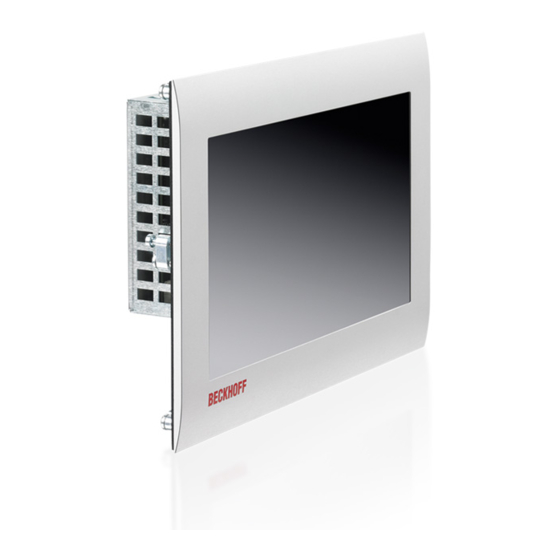
2.1 Product overview CP690x-0001-0000 | “Economy” built-in Control Panel with DVI/USB Extended interface The CP6900-0001-0000 and CP6906-0001-0000 “Economy” Control Panel expand the IPC entry-level class by a built-in Control Panel with DVI/USB extended interface. The Panel are designed for installation in the front of a control cabinet and have a 7-inch or 10.1-inch touch screen display. -
Page 10: Appropriate Use
The Control Panel must not be used where there is a risk of explosion. Danger 2.3 Access to the connectors The connectors of the Control Panel are located at the lower rear side of the housing. Picture: Bottom view CP6900-0001-0000/ CP6906-0001-0000... -
Page 11: Interfaces
2.4.3 USB in (X104) X104 USB type B, PCB installation (FCI 61729-0010B USB Receptacle B-Type) The Control Panel is connected with the Industrial PC via the USB port (X 104, connector type B). USB2.0 standard is supported. Signal Signal CP6900-0001-0000/ CP6906-0001-0000... -
Page 12: Usb-Extended Input (X105)
Signal Signal Rx2- Rx3+ Rx2- + 5V DVI Rx4- Rx4+ Rx0- DDC CLK Rx0+ DDC DAT AV SYNC Rx5- Rx1- Rx5+ Rx1+ RxC+ Rx3- RxC- 2.4.6 Ground connection The Panel PC is grounded via the M4-screw connection (Ground). CP6900-0001-0000/ CP6906-0001-0000... -
Page 13: Connection Kits
50 m DVI cable, 50 m CAT 5 cable for USB-E, USB to USB-E converter CU8800 for mounting rail installation close to the PC and 1 m USB cable to connect the USB to USB-E converter to the PC CP6900-0001-0000/ CP6906-0001-0000... -
Page 14: Installation
4. Please keep the associated paperwork. It contains important information for handling the unit. 5. Check the contents for visible shipping damage. If you notice any shipping damage or inconsistencies between the contents and your order, you should notify Beckhoff Service. CP6900-0001-0000/ CP6906-0001-0000... -
Page 15: Mounting
1. Insert the Control Panel at the intended control cabinet wall position and protect it from falling out, prior to final mounting. 2. Release the clamping levers, turn the clamping levers to the side and retighten the screws (see chapter Mounting of the Control Panel). CP6900-0001-0000/ CP6906-0001-0000... -
Page 16: Mounting Of The Control Panel
1 mm and 5 mm. 1. Insert the Control Panel into the cutout. 2. Release the clamping levers with a 2.5 mm Allen key. 3. Turn the clamping levers to the side. 4. Retighten the screws. CP6900-0001-0000/ CP6906-0001-0000... -
Page 17: Fitting The Power Supply Cable
Put the plug connector into that lower part of the stain relief housing. Tighten the lacing cord and pinch off the plastic strap. Fixing the upper part of the stain relief housing Fix the upper part of the stain relief housing by snapping it onto the lower part. CP6900-0001-0000/ CP6906-0001-0000... -
Page 18: Connecting The Control Panel
Earthing connections dissipate interference from external power supply cables, signal cables or cables to peripheral equipment. Establish a low-impedance connection from the earthing point on the Control Panel housing (see chapter Ground connection) to the central earthing point on the control cabinet wall, in which the computer is being installed. CP6900-0001-0000/ CP6906-0001-0000... -
Page 19: Operating Instructions
The touch screen may only be actuated by finger tips or with the touch screen pen. The operator may wear gloves but there must be no hard particles such as metal shavings, Warning glass splinters embedded in the glove. CP6900-0001-0000/ CP6906-0001-0000... -
Page 20: Servicing And Maintenance
Housing components (polycarbonate, polyamide (PA6.6)) are suitable for plastic recycling. • Metal parts can be sent for metal recycling. • Electronic parts such as disk drives and circuit boards must be disposed of in accordance with national electronics scrap regulations. CP6900-0001-0000/ CP6906-0001-0000... -
Page 21: Troubleshooting
No power supply to the Control Check power supply cable function Panel/ Industrial PC Correctly connect cable Call Beckhoff Service Cable not connected Computer boots, software starts, Cause of the fault is either in the Call the manufacturer of the... -
Page 22: Assembly Dimensions
Assembly dimensions 7 Assembly dimensions CP6900-0001-0000 Notice mounting orientation The assembly of the unit must take place with the orientation diagrammed here. Warning All dimensions are in mm. Front view Side view Rear view with cutout-dimensions CP6900-0001-0000/ CP6906-0001-0000... - Page 23 Assembly dimensions CP6906-0001-0000 Notice mounting orientation The assembly of the unit must take place with the orientation diagrammed here. Warning All dimensions are in mm. Ansicht von vorne Front view Side view Rear view with cutout-dimensions CP6900-0001-0000/ CP6906-0001-0000...
-
Page 24: Technical Data
Do not use the Control Panel in areas of explosive hazard! Danger Pixel errors Pixel errors in the TFT display are production-caused and represent no complaint- reason! Note Product name CP6900-0001-0000/ CP6906-0001-0000 Dimensions (B x H x T) See chapter Assembly dimensions Weight CP6900-0001-0000: approx. 1.4 kg CP6906-0001-0000: approx. -
Page 25: Appendix
Please contact your Beckhoff branch office or partner company for local support and service on Beckhoff products! The contact addresses for your country can be found in the list of Beckhoff branches and partner companies: www.beckhoff.com. You will also find further documentation for Beckhoff components there. -
Page 26: Approvals For Usa And Canada
Technological changes to the device may cause the loss of the FCC approval. Note 9.4 FCC Approval for Canada FCC: Canadian Notice This equipment does not exceed the Class A limits for radiated emissions as described in the Radio Interference Regulations of the Canadian Department of Communications. CP6900-0001-0000/ CP6906-0001-0000...
Need help?
Do you have a question about the CP6900-0001-0000 and is the answer not in the manual?
Questions and answers