Beckhoff CP39 Series Manual
Hide thumbs
Also See for CP39 Series:
- Installation and operating manual (30 pages) ,
- Manual (55 pages)
Table of Contents
Advertisement
Quick Links
Advertisement
Chapters
Table of Contents

Related Manuals for Beckhoff CP39 Series


Summary of Contents for Beckhoff CP39 Series
- Page 1 Manual | EN CP39xx Control Panel 9/22/2021 | Version: 3.1...
-
Page 3: Table Of Contents
Table of contents Table of contents 1 Notes on the documentation ........................ 5 2 For your safety............................ 6 Description of safety symbols ...................... 6 Intended use ............................ 6 Fundamental safety instructions ...................... 7 Operator's obligation to exercise diligence .................. 7 3 Product overview............................ 8 Structure ............................ 10 CP39xx-0000 interface description.................... 11 3.2.1 Power supply ........................ - Page 4 Table of contents Version: 3.1 CP39xx...
-
Page 5: Notes On The Documentation
Copyright © Beckhoff Automation GmbH & Co. KG. Publication of this document on websites other than ours is prohibited. Offenders will be held liable for the payment of damages. All rights reserved in the event of the grant of a patent, utility model or design. -
Page 6: For Your Safety
Exclusion of liability Beckhoff shall not be liable in the event of non-compliance with this documentation and thus the use of the devices outside the documented operating conditions. -
Page 7: Fundamental Safety Instructions
For your safety Fundamental safety instructions The following safety instructions must be observed when handling the device. Application conditions • Do not use the device under extreme environmental conditions. Protect the device from moisture and heat. • Never use the device in potentially explosive atmospheres. •... -
Page 8: Product Overview
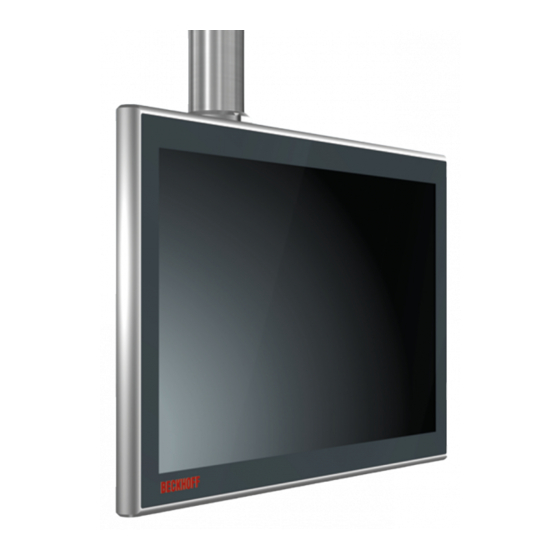
Product overview Product overview The Beckhoff Panel generation with industrial multi-touch display is designed for installation on the mounting arm. The devices offer suitable solutions for a variety of applications. The model variety ranges from different display sizes and formats to custom models. -
Page 9: Fig. 2 Cp39Xx_Toolboard And Handle
Product overview Mechanical extensions You have the possibility to order the control panel with mechanical extensions such as a toolboard (1) or a handle (2) (see Fig. 2). The extensions are mounted ex factory. The following ordering options are available to you: Table 1: Ordering options for toolboards and handle Order identifier... -
Page 10: Structure
Display and touch screen glass Operating the Control Panel Connection block Control Panel interfaces accessible Optional USB interface under screw Connection of peripheral devices Optional mounting arm adapter Beckhoff adapter for installation on the mounting arm tube from below Version: 3.1 CP39xx... -
Page 11: Cp39Xx-0000 Interface Description
The interfaces are freely accessible (see Fig. 4). Fig. 4: CP39xx-0000_connection block If you have ordered the Control Panel with Beckhoff mounting arm adapter, the connections are located inside the adapter. You must first gain access to the interfaces. The procedure is the same, regardless of whether you have ordered the mounting arm adapter with upwards or downwards orientation. - Page 12 Panel, so that the Control Panel remains switched on during voltage fluctuations. The plug is included in the delivery. You can obtain a replacement plug from your Beckhoff Sales using the following ordering option: • C9900-P916: Power supply connector for CP39xx, round connector IP65 with strain relief for the external supply cable Version: 3.1...
-
Page 13: Dvi Extended Input
Product overview 3.2.2 DVI Extended input The CP39xx-0000 Control Panel has a DVI Extended input (X102) with IP 65 protection class. It is used to transmit the graphics signal from the Industrial PC to the Control Panel. The graphics signal is transferred directly via a DVI cable over a distance of 50 m max. Such a cable length leads to strong distortion of the graphics signal on arrival at the Control Panel. -
Page 14: Usb Extended Input
Product overview 3.2.3 USB Extended input The CP39xx-0000 Control Panel has a USB Extended input (X103) with IP 65 protection class. The Control Panel is connected to the CU8801 USB to USB Extended converter box via the interface. To realize a distance of 50 m without hubs, USB Extended converts the USB signal so that it can be transmitted via a 50 m CAT-5 cable. -
Page 15: Cp39Xx-0010 Interface Description
The interfaces are freely accessible (see Fig. 9). Fig. 9: CP39xx-0010_connection block If you have ordered the Control Panel with Beckhoff mounting arm adapter, the connections are located inside the adapter. You must first gain access to the interfaces. The procedure is the same, regardless of whether you have ordered the mounting arm adapter with upwards or downwards orientation. -
Page 16: Power Supply
Panel, so that the Control Panel remains switched on during voltage fluctuations. The plug is included in the delivery. You can obtain a replacement plug from your Beckhoff Sales using the following ordering option: • C9900-P916: Power supply connector for CP39xx, round connector IP65 with strain relief for the external supply cable 3.3.2... -
Page 17: Fig. 13: Cp39Xx-0010_Cp-Link 4
Product overview On an Industrial PC with PCIe module, CP-Link 4 is available as a Two Cable Display Link. The Control Panel can be connected directly to the Industrial PC via the module. USB 2.0 (100 Mbit/s) and DVI are transmitted together via a CP-Link 4 cable. -
Page 18: Fig. 15 Cp39Xx-0010_Cp-Link 4, Cu8803
Product overview C6032-00x0 with PCIe compact module for CP-Link 4 CP-Link 4 (100 m) CU8803-0000 DP to DVI CP-Link 4 (100 m) DP to DVI CP-Link 4 (100 m) Fig. 15: CP39xx-0010_CP-Link 4, CU8803 The following ordering options are available for the transmitter boxes: •... -
Page 19: Optional Usb Interface
• USB (order identifier: C9900-E274) If you have ordered the device with a Beckhoff mounting arm adapter, the additional USB interface is located on the adapter. On a device without a mounting arm adapter, the interface is located at the side of the connection block. -
Page 20: Name Plate
Product overview Name plate The name plate is shown as an example of all versions of the Control Panel. xxxxxxxx Fig. 18: CP39xx_name plate Table 9: Legend for CP39xx name plate Description Model: The last four digits indicate the product version. Serial number (BTN) Date of manufacture Display Touch screen... -
Page 21: Connection Cables/Connection Kits
Product overview Connection cables/connection kits Different connection kits or connection cables are available, depending on the product version. 3.6.1 CP39xx-0000 connection kits The following connection kits are available for the CP39xx-0000: Connection kits Description C9900-K630 3 m connection kit for CP39xx-0000, consisting of: 3 m DVI cable, 3 m CAT-5 cable for USB-E-2.0, CU8801 USB-to-USB-E-2.0 converter for DIN rail mounting next to the PC and 1 m USB cable for connecting the USB-to- USB-E-2.0 converter to the PC... -
Page 22: Cp39Xx-0010 Connection Cable
Product overview 3.6.2 CP39xx-0010 connection cable The following connection cables are available for the CP39xx-0010: Table 10: CP39xx-0010 connection cable Connection cable Description C9900-K669 RJ45 connection cable CAT.6 , 1 m, one end with IP 65 connector for Control Panel CP39xx-0010 or CPX39xx-0010 C9900-K667 RJ45 connection cable CAT.6 , 3 m, one end with IP 65 connector for Control... - Page 23 Product overview Connection cable Description C9900-K724 RJ45 connection cable CAT.6 , 3 m, one end with IP 65 connector for Control Panel CP39xx-0010 or CPX39xx-0010, drag-chain suitable C9900-K704 RJ45 connection cable CAT.6 , 5 m, one end with IP 65 connector for Control Panel CP39xx-0010 or CPX39xx-0010, drag-chain suitable C9900-K705 RJ45 connection cable CAT.6...
-
Page 24: Commissioning
Beckhoff protective film. The film provides short-term protection for a few days. You can either order a Beckhoff protective film individually and fit it yourself retrospectively, or you can order the film for fitting directly ex works. -
Page 25: Table 12 Ordering Options: Film Fitted Ex Works
Commissioning Table 12: Ordering options: Film fitted ex works Ordering option Description C9900-T217 Adhesive protective film for Panel PCs and Control Panels with 7-inch display, for fitting onto the glass pane ex works C9900-T218 Adhesive protective film for Panel PCs and Control Panels with 12-inch display, for fitting onto the glass pane ex works C9900-T237 Adhesive protective film for Panel PCs and Control Panels with 12.1-inch display, for... -
Page 26: Transport And Unpacking
5. Check the contents for visible shipping damage. 6. In case of discrepancies between the package contents and the order, or in case of transport damage, please inform Beckhoff Service (see Chapter 9.1 Service and support [} 47]). Version: 3.1 CP39xx... -
Page 27: Mounting
In the basic configuration, there is a connection block with four M6 threaded holes on the rear side of the housing. The Control Panel can be installed above this on a mounting arm system. The Control Panel can optionally be ordered with the Beckhoff mounting arm adapter already fitted. The following ordering options are available: Table 13: Mounting arm adapter ordering options... -
Page 28: Fig. 20 Cp39Xx_Cable Duct
Commissioning Fig. 20: CP39xx_cable duct The cables for the push button extension C9900-G02x run through the mounting arm tube into the mounting arm adapter and onwards through the cable duct into the push button extension. You have to open both the cable duct and the push button extension in order to route the cables. -
Page 29: Fig. 22 Cp39Xx_Opening The Push Button Extension
If you have chosen a device with a mounting arm adapter, you must fit the mounting arm tube yourself. The procedure for fitting the mounting arm adapters with upwards or downwards orientation is the same. Among other tools you need a hook wrench for the installation. You can order this from your Beckhoff Sales using the following order identifier: •... - Page 30 Commissioning The mounting arm adapter facilitates tilting of the Control Panel fitted to the mounting arm tube by +/- 20 ° and rotate it by +/- 165 °. Version: 3.1 CP39xx...
-
Page 31: Connecting The Control Panel
Commissioning Connecting the Control Panel CAUTION Risk of electric shock Dangerous touch voltages can lead to electric shock. To avoid electric shock, adhere to the following point: • Never connect or disconnect the device cables during a thunderstorm. • Provide protective earthing for handling the device. To prepare the Control Panel for operation, you have to connect it. -
Page 32: Grounding The Control Panel
Panel. If the device is equipped with a connection block, the protective earth connection is located directly next to the connections. For a device with a Beckhoff mounting arm adapter, the connection is located in the connection compartment (see Fig. 22). -
Page 33: Routing The Cables In The Mounting Arm Adapter
Depending on the device equipment, the connections are either located at the connection block at the rear of the Control Panel or inside the mounting arm adapter. If you have ordered the Control Panel with a Beckhoff mounting arm adapter, it is essential that you observe the cable routing shown in Fig. 25 in order to avoid cable damage. -
Page 34: Fig. 26 Cp39Xx_Cable Routing Procedure
Commissioning Fig. 26: CP39xx_cable routing procedure In the case of the CP39xx-0000 you also have to fasten the power cable that lies further to the outside to a strain relief plate in addition to the strain relief rail (see fig. 27). To do this, pull the cable through under the plate and then fasten the cable to the plate with cable ties. -
Page 35: Push Button Extension Cable Routing
M20 cable gland and the cable duct into the push button extension. Beckhoff takes care of the wiring of the C9900-G05x push button extension for you. Therefore, you can order ready-to-use cables from Beckhoff Sales. More detailed information on the cable options and the wiring diagram can be found in the manual for the C9900-G05x. -
Page 36: Connecting Cables And Power Supply
Commissioning 4.3.4 Connecting cables and power supply NOTE Incorrect connection procedure Incorrect procedure when connecting the cables and the power supply can cause hardware damage. • Follow the documented procedure for connecting the cables and the power supply. • Always connect all cables first and only then switch on the power supply. •... - Page 37 Commissioning • Voltage drop: 1.8 A * 0.475 Ohm = 0.85 V With a CP39xx-0010 with CP-Link 4 and CU8803 transmitter box, you only have to pay attention to the voltage on the supply line to the transmitter box. More detailed information can be found in the manual for the CU8803.
-
Page 38: Decommissioning
Decommissioning Decommissioning NOTE Hardware damage due to power supply A connected power supply can cause damage to the Control Panel during disassembly. • Disconnect the power supply from the device before starting to disassemble it. When taking the Control Panel out of operation, you must first disconnect the power supply and cables. You can then dismantle the device. -
Page 39: Fig. 30 Cp39Xx-0000_Cable Ties On Strain Relief Plate
Decommissioning Fig. 30: CP39xx-0000_cable ties on strain relief plate In the case of the CP39xx-0000 and CP39xx-0010, release all cables from the strain relief rail by following the steps below as shown in fig. 27: 1. Sever the cable ties. 2. Loosen the Torx TX20 screw of the strain relief rail (section A). 3. -
Page 40: Disassembly And Disposal
Decommissioning To disconnect the cables from the Control Panel, proceed as follows: 1. Make a note of the wiring configuration, if you wish to restore it with another device. 2. Disconnect all data transfer cables from the Control Panel. 3. Finally, disconnect the ground connection. Disassembly and disposal Before you can remove the Control Panel from the mounting arm tube, you must first disconnect the power supply and the cables (see chapter 5.1 Disconnecting the power supply and cables [} 38]). -
Page 41: Fig. 33 Cp39Xx_Toolboard And Handle
Decommissioning Fig. 33: CP39xx_Toolboard and handle Disposal of the Control Panel When disposing of the Control Panel the national electronic waste regulations must be followed. CP39xx Version: 3.1... -
Page 42: Maintenance
Cleaning the front screen You can clean the front screen of the Control Panel during operation. In order to avoid inadvertent touch entries when doing this, you must first set the device to "Cleaning Mode" with the help of the Beckhoff Control Tool. -
Page 43: Fig. 34 Cp39Xx_Select "Cleaning Mode
5 and 120 seconds. Right-click the sun symbol again and click "Options". Now select the appropriate period (see fig. 35). Fig. 35: CP39xx_Configuration "Cleaning Mode" Repair Only the manufacturer may repair the device. If a repair should be necessary, contact Beckhoff Service (see Chapter 9.1 Service and support [} 47]). CP39xx Version: 3.1... -
Page 44: Troubleshooting
Problem with the cable connections CP39xx-0000: Check the DVI cable connection CP39xx-0010: 1. Check the cable connec- tions 2. Check the CU880x diagnos- tic LEDs 3. Check the power supply Beckhoff recommends using available Beckhoff connection cables and connection kits. Version: 3.1 CP39xx... -
Page 45: Technical Data
Technical data Technical data Table 15: Technical data Product designation CP39xx-0000 Weights (with connection block/ CP3907: 1.8 kg with mounting arm adapter) CP3912: 3.4 kg/ 4.2 kg CP3913: 3.1 kg/ 3.9 kg CP3915: 3.9 kg/ 4.7 kg CP3916: 4.5 kg/ 5.3 kg CP3918: 5.5 kg/ 6.3 kg CP3919: 6.1 kg/ 6.9 kg CP3921: 6.6 kg/ 7.4 kg... - Page 46 Technical data Product designation CP39xx-0010 Weights (with connection block/ CP3907: 1.8 kg with mounting arm adapter) CP3912: 3.4 kg/ 4.2 kg CP3913: 3.1 kg/ 3.9 kg CP3915: 3.9 kg/ 4.7 kg CP3916: 4.5 kg/ 5.3 kg CP3918: 5.5 kg/ 6.3 kg CP3919: 6.1 kg/ 6.9 kg CP3921: 6.6 kg/ 7.4 kg CP3924: 7.6 kg/ 8.4 kg...
-
Page 47: Appendix
Phone: + 49 (0) 5246/963-0 Fax: + 49 (0) 5246/963-198 e-mail: info@beckhoff.de The addresses of the worldwide Beckhoff branch offices and agencies can be found on our website at http:// www.beckhoff.com/. You will also find further documentation for Beckhoff components there. -
Page 48: Approvals
Appendix Approvals The following table shows the approvals of the Control Panels based on the product variant: Table 16: CP39xx approvals Product version by connection type approvals CP39xx-0000 USB/DVI connection CE, EAC, UL CP39xx-0010 CP-Link 4 connection CE, EAC, UL You will find all other applicable approvals on the nameplate of your device. FCC approvals for the United States of America FCC: Federal Communications Commission Radio Frequency Interference Statement This device was tested and complies with the limits for a digital device of class A, according part 15 of the... - Page 49 List of figures List of figures Fig. 1 CP39xx_without and with push button extension ................ Fig. 2 CP39xx_Toolboard and handle ....................Fig. 3 CP39xx_configuration........................Fig. 4 CP39xx-0000_connection block ....................Fig. 5 CP39xx-0000_access to interfaces ..................... Fig. 6 CP39xx_voltage socket pin numbering ..................Fig.
- Page 50 List of tables List of tables Table 1 Ordering options for toolboards and handle ................Table 2 CP39xx configuration legend....................... Table 3 Voltage socket pin assignment ....................Table 4 DVI Extended interface pin assignment..................Table 5 USB-E input pin assignment......................Table 6 Voltage socket pin assignment ....................
- Page 52 More Information: www.beckhoff.com/cp39xx Beckhoff Automation GmbH & Co. KG Hülshorstweg 20 33415 Verl Germany Phone: +49 5246 9630 info@beckhoff.com www.beckhoff.com...
Need help?
Do you have a question about the CP39 Series and is the answer not in the manual?
Questions and answers