
Subscribe to Our Youtube Channel
Related Manuals for Beckhoff CP39-14-0010 Series


Summary of Contents for Beckhoff CP39-14-0010 Series
- Page 1 Manual | EN CP39xx-14xx-0010 Stainless steel multi-touch Control Panel with CP-Link 4 10/12/2021 | Version: 1.1...
-
Page 3: Table Of Contents
Table of contents Table of contents 1 Notes on the documentation ........................ 5 2 For your safety............................ 6 Description of safety symbols ...................... 6 Intended use ............................ 6 Fundamental safety instructions ...................... 6 Operator's obligation to exercise diligence .................. 7 3 Product overview............................ 8 Structure ............................ 10 Interface description ........................ 11 3.2.1 Power supply, 4-pin round connector ................ - Page 4 Table of contents Version: 1.1 CP39xx-14xx-0010...
-
Page 5: Notes On The Documentation
Copyright © Beckhoff Automation GmbH & Co. KG. Publication of this document on websites other than ours is prohibited. Offenders will be held liable for the payment of damages. All rights reserved in the event of the grant of a patent, utility model or design. -
Page 6: For Your Safety
Exclusion of liability Beckhoff shall not be liable in the event of non-compliance with this documentation and thus the use of the devices outside the documented operating conditions. Description of safety symbols The following safety symbols are used in these operating instructions. -
Page 7: Operator's Obligation To Exercise Diligence
For your safety • Do not carry out any work on the device while it is live. Always switch off the supply voltage for the device before mounting it, replacing device components or rectifying malfunctions. • Never connect the device during a thunderstorm. There is a risk of electric shock. •... -
Page 8: Product Overview
Product overview Product overview The Control Panels of the CP39xx-14xx-00x0 series meet the strict hygiene requirements of the pharmaceutical, food and packaging industries and can be used directly in the field. A mounting arm adapter can be ordered separately for installation on a 48 mm mounting arm system. The adapter protects all connections and cables from contamination and chemical impacts. - Page 9 Product overview Push button extension The following Control Panels can be ordered with push button extension ex works. • CP3913-1401-0010 • CP3913-1414-0010 • CP3916-1401-0010 • CP3916-1414-0010 • CP3918-1401-0010 • CP3918-1414-0010 CP39xx-14xx-0010 Version: 1.1...
-
Page 10: Structure
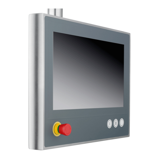
Product overview Structure Fig. 1 shows an example of the device configuration representing all CP39xx-14xx-0010 versions. The Control Panel connection interfaces vary, depending on the product version. Otherwise, there are no differences in the external design of the device. Fig. 1: CP39xx-14xx-0010_configuration Table 1: Key for CP39xx-14xx-0010 configuration Component Description... -
Page 11: Interface Description
Product overview Interface description The connection options of the CP39xx-14xx-0010 vary, depending on the product version. The following view illustrates the configuration of the connector panels. • CP39xx-1400-0010 (A) connection section • CP39xx-1401-0010 (B) connection section • CP39xx-1414-0010 (C) connection section Fig. 2: CP39xx-14xx-0010_connection section Table 2: Key for CP39xx-1400-0010, CP39xx-1401-0010, CP39xx-1414-0010 connection section Component... -
Page 12: Power Supply, 4-Pin Round Connector
There should be at least 22 V at the power supply plug of the Control Panel, so that the Control Panel remains switched on during voltage fluctuations. You can obtain a replacement plug from your Beckhoff Sales using the following ordering option: •... -
Page 13: Cp-Link 4
Product overview 3.2.2 CP-Link 4 The CP39xx-14xx-0010 Control Panel has a CP-Link 4 input in the form of an 8-pin M12 socket. Via the interface the Control Panel can be connected to an Industrial PC over a distance of up to 100 m. The device can be connected to the Industrial PC either directly with a corresponding PCIe module or indirectly via an intermediate CU8802/ CU8803 transmitter box. - Page 14 Product overview CP-Link 4 with transmitter box If the Industrial PC is not equipped with a PCIe module, a transmitter box is required for connecting a CP39xx-14xx-0010. The transmitter boxes CU8802-000x (Two Cable Display Link) and CU8803-000x (One Cable Display Link) are available for this purpose. With the CU8802-000x, the Industrial PC is connected to the transmitter box via USB and DP/DVI.
- Page 15 Product overview With the CU8803-000x, the Industrial PC is also connected to the transmitter box via USB and DP/DVI. The transmitter box is then connected to the Control Panel via the CP-Link 4 connection of the transmitter box using a CP-Link 4 cable. With this box, USB, DP/DVI and power supply can be transmitted together via the cable (One Cable Display Link).
-
Page 16: 19-Pin Round Connector For Signal And Power Supply
Product overview 3.2.3 19-pin round connector for signal and power supply The push button extension of the CP39xx-1401-0010 is connected via the 19-pin M23 socket. Fig. 8: CP39xx-1401-0010_signal and power supply, 19-pin Table 5: Pin assignment of the 19-pin voltage socket Signal Emergency stop (break contact 1) Emergency stop (break contact 1) Emergency stop (break contact 2) -
Page 17: Optional Interface
Product overview Optional interface You can expand the Control Panels beyond the basic equipment to include an externally routed USB interface in the mounting arm adapter. The following ordering option is available for this purpose. Table 7: USB interface ordering option Options Description C9900-E299... -
Page 18: Name Plate
Product overview Name plate The name plate provides information about the Control Panel equipment. xxxxxxxx Fig. 11: CP39xx-14xx-00x0_name plate Key for CP39xx-14xx-0010 name plate Description Device name Serial number (BTN) Date of manufacture Display Touch screen 24 V power supply, NEC class 2 FCC approval Symbols Note: Here you will find the symbols that apply to the device: CE, EAC, UKCA,... -
Page 19: Connecting Cable
Product overview Connecting cable Optionally, ready-made connection cables for all connections are available in various lengths. You can order them using the following article descriptions. Power supply line Fig. 12: CP39xx-1400-0010 CP39xx-1414-0010_power supply, 4-pin Table 11: 4-pin power supply cable for CP39xx-1400-0010 CP39xx-1414-0010 Connection cable Description C9900-K742... - Page 20 Product overview signal line Fig. 14: CP39xx-1401-0010_power supply, 19-pin Table 13: CP39xx-1401-0010 19-pin signal line Connection cable Description C9900-K618 Signal and power supply cable for push button extension, drag-chain suitable, length 5 m, 3x1mm² + 16x0.34mm², pre-assembled, M23 socket IP65, screwable, 19-core, second end open C9900-K619 Signal and power supply cable for push button extension, drag-chain suitable, length 10 m, 3x1mm²...
- Page 21 Product overview Connecting cable Fig. 15: CP39xx-14xx-0010_CP-Link 4 connection cable Table 14: CP39xx-14xx-0010 CP-Link connection cable Connection cable Description C9900-K667 RJ 45 Cat. 6A connection cable, 3 m, one end with IP 65 connector C9900-K652 RJ 45 Cat. 6A connection cable, 5 m, one end with IP 65 connector C9900-K653 RJ 45 Cat.
-
Page 22: Optional Transmitter Box Cu8802-000X/ Cu8803-000X
Product overview Optional transmitter box CU8802-000x/ CU8803-000x Different transmitter boxes are available depending on the product version. 3.8.1 CU8802-000x for CP39xx-14xx-0010 Table 15: CP-Link 4 extender CU8802-0000 Accessories Description CU8802-0000 CP-Link 4 Extender-Tx for connecting a Control Panel with CP-Link 4 interface CP29xx-0010, CP39xx-0010 or CPX39xx-0010 –... -
Page 23: Cu8803-000X For Cp39Xx-14Xx-0010
Product overview 3.8.2 CU8803-000x for CP39xx-14xx-0010 Table 17: CP-Link 4 extender CU8803-0000 Accessories Description CU8803-0000 CP-Link 4 Extender-Tx for connecting a Control Panel with CP-Link 4 interface CP29xx-0010, CP39xx-0010 or CPX39xx-0010 – 1 USB input with USB B socket for connection to the PC at a distance of 1 m –... -
Page 24: Commissioning
5. Check the contents for visible shipping damage. 6. In case of discrepancies between the package contents and the order, or in case of transport damage, please inform Beckhoff Service (see Chapter 10.1 Support and Service [} 51]) Version: 1.1 CP39xx-14xx-0010... -
Page 25: Mounting
Control Panel for installation on the mounting arm system. In addition, the mounting arm adapter is equipped with anti-twist protection, so that damage to the connection cable and the Control Panel is prevented. The following ordering options are available, if you require a Beckhoff mounting arm adapter for the installation. -
Page 26: Installing The Mounting Arm Adapter
Commissioning 4.2.1 Installing the mounting arm adapter Before mounting the Beckhoff mounting arm adapter, you have to decide whether to install it from above or below. Fig. 17: CP39xx-140x-0010_mounting arm adapter orientation In addition, an optional tilt adapter can be customer-mounted on the Control Panel. This option allows the Control Panel to be tilted by 10°. - Page 27 Commissioning Fitting the mounting arm adapter without tilt adapter C9900-M764 To fasten the mounting arm adapter to the Control Panel, follow the steps below, shown in Figs. 18 & 19: 1. Release the four M4 screws of the two side covers (section A). 2.
- Page 28 Commissioning Installing the mounting arm adapter with tilt adapter C9900-M764 To fasten the mounting arm adapter with tilt adapter to the Control Panel, follow the steps below, shown in Figs. 20 - 24: 1. Release the four M4 screws of the side cover (section A). 2.
- Page 29 Commissioning 8. Use the M5 screws provided to fasten the mounting arm adapter to the tilt adapter. A tightening torque of 4 Nm is recommended (section H). 9. Connect the cables coming out of the side to the Control Panel (section I). Fig. 23: CP39xx-14xx-0010_installation of mounting arm adapter with tilt adapter 10.
-
Page 30: Dimensions
Commissioning 4.2.2 Dimensions All dimensions are in mm. Figure 25 shows the dimensions of the 12.1-inch Control Panel. 377,7 Fig. 25: CP3913-1400-0010_dimensions Figure 26 shows the dimensions of the 15.6-inch Control Panel. Fig. 26: CP3916-1400-0010_dimensions Figure 27 shows the dimensions of the 18.5-inch Control Panel. Fig. 27: CP3918-1400-0010_dimensions Figures 28 and 29 show the dimensions of the 12.1-inch Control Panel with fitted push button extension. - Page 31 Commissioning 377,7 33,1 Fig. 28: CP3913-1401-0010_dimensions 377,7 33,1 Fig. 29: CP3913-1414-0010_dimensions Figures 30 and 31 show the dimensions of the 15.6-inch Control Panel with fitted push button extension. 32,6 Fig. 30: CP3916-1401-0010_dimensions CP39xx-14xx-0010 Version: 1.1...
- Page 32 Commissioning 32,6 Fig. 31: CP3916-1414-0010_dimensions Figures 32 and 33 show the dimensions of the 18.5-inch Control Panel with fitted push button extension. 33,1 Fig. 32: CP3918-1401-0010_dimensions 33,1 Fig. 33: CP3918-1414-0010_dimensions Version: 1.1 CP39xx-14xx-0010...
-
Page 33: Connecting The Control Panel
Commissioning Connecting the Control Panel CAUTION Risk of electric shock Dangerous touch voltages can lead to electric shock. To avoid electric shock, observe the following: • Never connect or disconnect the device cables during a thunderstorm. • Provide protective earthing for handling the device. To prepare the Control Panel for operation, you have to connect it. -
Page 34: Circuit Diagrams
Commissioning 4.3.1 Circuit diagrams You can use the following circuit diagrams to plan your wiring in advance. In addition, you will receive a circuit diagram for your device. Fig. 34: CP39xx-1401_circuit diagram Version: 1.1 CP39xx-14xx-0010... - Page 35 Commissioning Fig. 35: CP39xx-1414-0010_circuit diagram CP39xx-14xx-0010 Version: 1.1...
-
Page 36: Grounding The Control Panel
Commissioning 4.3.2 Grounding the Control Panel Potential differences are minimized and electrical currents are diverted to the ground through grounding or potential equalization of electronic devices. This is to prevent dangerous touch voltages and electromagnetic interference. The connection compartment of the CP39xx-14xx-0010 features an M6 protective conductor connection, through which you have to establish the low-resistance protective earthing and functional earthing for the Panel (see Fig. -
Page 37: Connecting Cables And Power Supply
Commissioning 4.3.3 Connecting cables and power supply NOTE Incorrect connection procedure Incorrect procedure when connecting the cables and the power supply can cause hardware damage. • Follow the documented procedure for connecting the cables and the power supply. • Always connect all cables first and only then switch on the power supply. •... - Page 38 Commissioning All data for the power consumption can be found in chapter 8 Technical data [} 49]. Version: 1.1 CP39xx-14xx-0010...
-
Page 39: Commissioning In The Twincat System Manager
Commissioning 4.3.4 Commissioning in the TwinCAT System Manager The switching contacts and the LED data are transmitted to the control/visualization PC via USB. Follow the steps below to connect the push button extension in the TwinCAT System Manager (Figs. 37 to 41): 1. - Page 40 Commissioning 4. First select the device that was found and confirm the selection with OK. Fig. 39: TwinCAT_device select 5. Confirm the request with Yes, in order to scan for boxes. Fig. 40: TwinCAT_scan boxes 6. Confirm the request whether to enable FreeRun with Yes. The device is inserted as a box in the tree view and displayed with the respective inputs/outputs (e.g.
- Page 41 Commissioning Fig. 41: TwinCAT_renaming terms and channels You can rename the individual channels of the respective terms, as shown in Fig. 41. CP39xx-14xx-0010 Version: 1.1...
-
Page 42: Decommissioning
Decommissioning Decommissioning NOTE Hardware damage due to power supply A connected power supply can cause damage to the Control Panel during disassembly. • Disconnect the power supply from the device before starting to disassemble it. When taking the Control Panel out of operation, you must first disconnect the power supply and cables. Afterwards, you can dismount the device from the mounting arm. - Page 43 Decommissioning Removing the mounting arm tube NOTE Damage to property due to falling down If the Control Panel is suspended from the ceiling and you release the set screw of the mounting arm adapter without securing it, the Control Panel will drop down. •...
- Page 44 Decommissioning Removing the mounting arm adapter with tilt adapter C9900-M764 To remove the mounting arm adapter with tilt adapter from the Control Panel, follow the steps below, shown in Figs. 44 - 45: 1. Release the six M5 screws (section A). 2.
-
Page 45: Maintenance
Cleaning the front screen You can clean the front screen of the Control Panel during operation. In order to avoid inadvertent touch entries when doing this, you must first set the device to "Cleaning Mode" with the help of the Beckhoff Control Tool. - Page 46 Maintenance Fig. 47: CP39xx-14xx-0010_cleaning mode configuration Repair Only the manufacturer may repair the device. If a repair should be necessary, contact Beckhoff Service (see Chapter 10.1 Support and Service [} 51]) Version: 1.1 CP39xx-14xx-0010...
- Page 47 NOTE Use of incorrect spare parts The use of spare parts not ordered from Beckhoff Service can lead to unsafe and faulty operation. • Only use spare parts that you have ordered from Beckhoff Service. Beckhoff Control Panels are manufactured from components of the highest quality and robustness. They are selected and tested for best interoperability, long-term availability and reliable function under the specified environmental conditions.
-
Page 48: Troubleshooting
Check the cable for the power Control Panel/ Industrial PC supply 1. Correctly connect cable. Cable not connected 2. Call Beckhoff Service Malfunction of the touch screen Poor or missing functional earth of Establish functional earth the device Poor or missing ground connection... -
Page 49: Technical Data
Technical data Technical data Product designation CP39xx-140x-0010 Weight CP3913-1400-0010 4.1 kg/ 6.5 kg Without/with mounting arm CP3913-1401-0010 5.0 kg/ 7.4 kg adapter CP3913-1414-0010 5.0 kg/ 7.4 kg CP3916-1400-0010: 6.0 kg/ 8.4 kg CP3916-1401-0010: 6.9 kg/ 9.3 kg CP3918-1400-0010: 7.4 kg/ 9.8 kg CP3918-1401-0010: 8.5 kg/ 10.9 kg CP3916-1414-0010: 6.9 kg/ 9.3 kg CP3918-1414-0010: 8.5 kg/ 10.9 kg... -
Page 50: Chemical Resistance Of Stainless Steel Panel With Flush-Mounted Touch Screen
Liquids and vapors that act on the panel for several minutes must temperature not exceed a temperature of 45 °C on the Control Panel. Flush-mounted Beckhoff touch screens are resistant to many solvents. The following solvents have been explicitly tested. Solvent resistance... -
Page 51: Appendix
Please contact your Beckhoff subsidiary or representative regarding local support and service for Beckhoff products. The addresses of Beckhoff’s branch offices and representatives round the world can be found on the internet pages: https://www.beckhoff.de You will also find further documentation for Beckhoff components there. -
Page 52: Approvals
Appendix 10.2 Approvals The Control Panel has the following approvals: Table 23: CP39xx-14xx-0010 approvals Product version according to connection type Approvals CP3913-1400-0010 CE, EAC, UKCA, FCC CP3913-1401-0010 CE, EAC, UKCA, FCC CP3913-1414-0010 CE, EAC, UKCA, FCC CP3916-1400-0010 CE, EAC, UKCA, FCC CP3916-1401-0010 CE, EAC, UKCA, FCC CP3916-1414-0010... - Page 54 More Information: www.beckhoff.com/cp39xx-1400-0010 Beckhoff Automation GmbH & Co. KG Hülshorstweg 20 33415 Verl Germany Phone: +49 5246 9630 info@beckhoff.com www.beckhoff.com...
Need help?
Do you have a question about the CP39-14-0010 Series and is the answer not in the manual?
Questions and answers