Table of Contents
Advertisement
Quick Links
Advertisement
Chapters
Table of Contents

Related Manuals for Beckhoff CP3921-15 00 0 Series


Summary of Contents for Beckhoff CP3921-15 00 0 Series
- Page 1 Manual | EN CP3921-15xx-00x0 Control Panel 2024-07-08 | Version: 1.0...
-
Page 3: Table Of Contents
Table of contents Table of contents 1 Notes on the documentation........................ 5 2 For your safety ............................ 6 Signal words............................ 6 Intended use ............................. 6 Fundamental safety instructions ....................... 7 Operator's obligation to exercise diligence.................. 7 Notes on information security...................... 8 3 Product overview ............................ - Page 4 Table of contents Version: 1.0 CP3921-15xx-00x0...
-
Page 5: Notes On The Documentation
EP1590927, EP1789857, EP1456722, EP2137893, DE102015105702 and similar applications and registrations in several other countries. ® EtherCAT is registered trademark and patented technology, licensed by Beckhoff Automation GmbH, Germany Copyright © Beckhoff Automation GmbH & Co. KG, Germany. The distribution and reproduction of this document as well as the use and communication of its contents without express authorization are prohibited. -
Page 6: For Your Safety
Exclusion of liability Beckhoff shall not be liable in the event of non-compliance with this documentation and thus the use of the devices outside the documented operating conditions. -
Page 7: Fundamental Safety Instructions
For your safety Fundamental safety instructions The following safety instructions must be observed when handling the device. Application conditions • Do not use the device under extreme environmental conditions. • Only use the device in hazardous areas if it is explicitly designed for this purpose. •... -
Page 8: Notes On Information Security
For your safety Notes on information security The products of Beckhoff Automation GmbH & Co. KG (Beckhoff), insofar as they can be accessed online, are equipped with security functions that support the secure operation of plants, systems, machines and networks. Despite the security functions, the creation, implementation and constant updating of a holistic security concept for the operation are necessary to protect the respective plant, system, machine and networks against cyber threats. -
Page 9: Product Overview
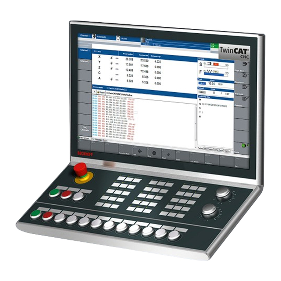
Product overview Product overview The Beckhoff Panel generation with industrial multi-touch display is designed for installation on the mounting arm. The devices offer suitable solutions for a variety of applications. The model variety ranges from different display sizes and formats to customer-specific models. -
Page 10: Fig. 2 Access Push-In Strips
Product overview Fig. 2: Access push-in strips Below you will find an overview of the arrangement of the push buttons and switches on the push button extension. Fig. 3: Overview push buttons and switches Version: 1.0 CP3921-15xx-00x0... -
Page 11: Table 1 Overview Push Buttons And Switches
Product overview Table 1: Overview push buttons and switches Position Type Color Contact via Directly wired Light source push but- contact 2 tons/ switches Emergency stop Normally open 2 normally switch contact closed contacts Illuminated push green Normally open Normally open LED, white button contact... -
Page 12: Structure
Product overview Structure Figure 4 shows the device configuration as an example of all CP3921-15xx-00x0 versions. The control panel connection interfaces vary, depending on the product version. Otherwise, there are no differences in the external design of the device. Fig. 4: Structure Table 2: Legend for CP3921-15xx-00x0 configuration Component Description... -
Page 13: Interface Description -0000
• DVI Extended input (X102) • USB Extended input (X103) For the control panel with Beckhoff mounting arm adapter, the connections are located inside the adapter. You must first gain access to the interfaces. The procedure is the same, regardless of whether you have ordered the mounting arm adapter with upwards or downwards orientation. -
Page 14: Power Supply
Product overview 3.2.1 Power supply The control panel is supplied with a nominal voltage of 24 V. The connection to the power supply as well as the connection of the push buttons S1-S4 of the push button extension is made via the 19-pin voltage socket (XS01). -
Page 15: Dvi Extended Input
Product overview 3.2.2 DVI Extended input The CP3921-15xx-0000 Control Panel has a DVI Extended input (X102). It is used to transmit the graphics signal from the industrial PC to the control panel. The graphics signal is transferred directly via a DVI cable over a distance of 50 m max. Such a cable length leads to strong distortion of the graphics signal on arrival at the control panel. -
Page 16: Usb Extended Input
Product overview 3.2.3 USB Extended input The CP3921-15xx-0000 Control Panel has a USB Extended input (X103). The interface is used to connect the control panel to the CU8801 USB-to-USB extended transmitter box. To realize a distance of 50 m without hubs, USB Extended converts the USB signal so that it can be transmitted via a 50 m CAT 5 cable. -
Page 17: Usb
Product overview 3.2.4 On the mounting arm adapter there is an additional USB interface under a screw cap according to IP65. The screw cap is attached via an internal rope and thus remains on the unit even after unscrewing. In order to gain access to the interface, unscrew the cap and let it dangle on the rope. -
Page 18: Interface Description --0010
• Power supply (XS01) • CP-Link 4 input (X102) For the control panel with Beckhoff mounting arm adapter, the connections are located inside the adapter. You must first gain access to the interfaces. The procedure is the same, regardless of whether you have ordered the mounting arm adapter with upwards or downwards orientation. -
Page 19: Power Supply
Product overview 3.3.1 Power supply The control panel is supplied with a nominal voltage of 24 V. The connection to the power supply as well as the connection of the push buttons S1-S4 of the push button extension is made via the 19-pin voltage socket (XS01). -
Page 20: Cp-Link-4 Input
Product overview 3.3.2 CP-Link-4 input The CP3921-15xx-0010 Control Panel has a CP-Link 4 input (X102) in the form of an 8-pin M12 socket. Via the interface, the control panel can be connected to an industrial PC at a distance of up to 100 m. The connection can be made either directly with an industrial PC with a corresponding PCIe module or indirectly via an intermediate transmitter box. -
Page 21: Usb
Product overview C6032-00x0 with PCIe compact module for CP-Link 4 CP-Link 4 (100 m) CU8802-0000 0000 DP to DVI CP-Link 4 (100 m) DP to DVI CP-Link 4 (100 m) Fig. 15: CP-Link 4, CU8802-00x0 The following ordering options are available for the transmitter boxes: •... -
Page 22: Fig. 17 Usb Interface Pin Numbering
Product overview Fig. 17: USB interface pin numbering Table 9: USB interface pin assignment Connection Vbus Version: 1.0 CP3921-15xx-00x0... -
Page 23: Name Plate
Product overview Name plate The name plate provides information about the control panel equipment. The name plate shown here serves only as an example. xxxxxxxx Fig. 18: Name plate Table 10: Legend for CP3921-15xx name plate Description Model: the last four digits indicate the product version. Serial number (BTN) Date of manufacture Display... -
Page 24: Circuit Diagrams
Product overview Circuit diagrams Fig. 19: Circuit diagram Version: 1.0 CP3921-15xx-00x0... -
Page 25: Fig. 20 Circuit Diagram
Product overview Fig. 20: Circuit diagram CP3921-15xx-00x0 Version: 1.0... -
Page 26: Commissioning
You can either order a Beckhoff protective film individually and fit it yourself retrospectively, or you can order the film for fitting directly ex factory. Please refer to the price list for the available protective films according to the display size of your device. -
Page 27: Transport And Unpacking
4. Check your delivery for completeness by comparing it with your order. 5. Check the contents for visible shipping damage. 6. In case of discrepancies between the package contents and the order, or in case of transport damage, please inform Beckhoff Service (see Chapter 9.1 Service and support). CP3921-15xx-00x0 Version: 1.0... -
Page 28: Mounting
Commissioning Mounting You can choose between the mounting arm adapter with downward orientation and the mounting arm adapter with upward orientation: Table 11: Ordering options Control Panel Order identifier Version CP3921-1500-0000 21.5-inch display (1920 x 1080) with CNC push button extension and C9900- M753 mounting arm from below, rotatable and tiltable mounting arm adapter for 48 mm round tube, clamping lever to lock the inclination 19-pin round connector for 24 V power supply and connection of buttons S1-... -
Page 29: Dimensions
Commissioning 4.2.1 Dimensions All dimensions are in mm. Figure 22 shows the dimensions of the CP3921-1500-0000 with the mounting arm adapter facing down. 185,7 537,9 156,6 Fig. 22: Dimensions Figure 23 shows the dimensions of the CP3921-1502-0000 with the mounting arm adapter facing up. 185,7 156,6 537,9... -
Page 30: Fig. 25 Dimensions
Commissioning 156,6 195,7 537,9 Fig. 25: Dimensions Version: 1.0 CP3921-15xx-00x0... -
Page 31: Mounting Arm Tube Installation
The procedure is the same regardless of the upward and downward orientation of the mounting arm adapters. Among other tools you need a hook wrench for the installation. You can order this from your Beckhoff Sales using the following order identifier: •... -
Page 32: Connecting The Control Panel
Commissioning Connecting the control panel CAUTION Risk of electric shock Dangerous touch voltages can lead to electric shock. To avoid electric shock, observe the following: • Never connect or disconnect the device cables during a thunderstorm. • Provide protective earthing for handling the device. To make the device ready for operation, you have to connect it. -
Page 33: Grounding The Control Panel
Commissioning 4.3.1 Grounding the control panel Potential differences are minimized and electrical currents are diverted to the ground through grounding or potential equalization of electronic devices. This is to prevent dangerous touch voltages and electromagnetic interference. The protective grounding of a device serves to avoid dangerous touch voltages. According to the EN 60204-1 standard (Chapter 8 Potential equalization), protective grounding is required if: •... -
Page 34: Routing The Cables In The Mounting Arm Adapter
Commissioning 4.3.2 Routing the cables in the mounting arm adapter NOTICE Cable damage due to incorrect cable routing Incorrect cable routing can cause cable damage when rotating and tilting the mounting arm adapter. • Be sure to route the cables inside the mounting arm adapter in the specified arrangement. The connections of the control panel are located inside the mounting arm adapter. -
Page 35: Fig. 29 Cable Routing Procedure
Commissioning The figure shows the steps, taking the CP3921-15xx-0000 as an example. The procedure is the same regardless of the product version. Fig. 29: Cable routing procedure The cables pass through the mounting arm tube into the connection compartment of the mounting arm adapter. -
Page 36: Connection Cables And Power Supply
Commissioning 4.3.3 Connection cables and power supply NOTICE Incorrect connection procedure Incorrect procedure when connecting the cables and the power supply can cause hardware damage. • Follow the documented procedure for connecting the cables and the power supply. • Always connect the cables first and only then switch on the power supply. •... -
Page 37: Twincat System Manager Connection
Commissioning TwinCAT System Manager connection During commissioning you must connect the push button extension in the TwinCAT System Manager. Follow the steps below: 1. Click at the top in the menu on File > New > Project and create a new TwinCAT XAE Project. 2. -
Page 38: Fig. 32 Select Device
Commissioning Fig. 32: Select device 5. Confirm the request with Yes, in order to scan for boxes. Fig. 33: Scan for box modules 6. Confirm the request whether to enable FreeRun with Yes. ð The device is inserted as a box in the tree view and displayed with the respective inputs and outputs (e.g. -
Page 39: Decommissioning
Decommissioning Decommissioning NOTICE Hardware damage due to power supply A connected power supply can cause damage to the device during disassembly. • Disconnect the power supply from the device before starting to disassemble it. When taking the control panel out of operation, you must first disconnect the power supply and cables. You can then dismantle the device. - Page 40 Decommissioning 2. Disconnect the control panel from the external 24 V power supply. 3. Loosen the screw connection between the voltage socket and the voltage connector. 4. Remove the voltage connector from the voltage socket. 5. Make a note of the wiring of all data transmission cables if you want to restore the cabling with another device.
-
Page 41: Disassembly And Disposal
Decommissioning Disassembly and disposal Before you can remove the control panel from the mounting arm tube, you must first disconnect the power supply and the cables (see chapter 5.1 Disconnecting the power supply and cables [} 39]). Disassembly mounting arm tube NOTICE Damage to property due to falling down If the control panel is suspended from the ceiling and you undo the slotted nut of the mounting arm adapter... -
Page 42: Maintenance
You can clean the front screen of the device during operation. In order to avoid inadvertent touch entries when doing this, you must first set the device to "Cleaning Mode" with the help of the Beckhoff Control Tool. Also make sure that you not only clean the display area, but also the edge of the glass pane. Impurities in... -
Page 43: Fig. 37 Select "Cleaning Mode
Maintenance Fig. 37: Select "Cleaning Mode" You can set the duration for which the panel PC should remain in "Cleaning Mode". The period can be set between 5 and 120 seconds. Right-click the sun symbol again and click "Options". Now select the appropriate duration (see Fig.). -
Page 44: Troubleshooting
Measures No control panel function Lack of power supply to the control Check the power supply cable panel Call Beckhoff Service Other cause The control panel only works Defective backlight in the display Call Beckhoff Service partially or only temporarily (e.g. -
Page 45: Technical Data
Weight 7.4 kg Supply voltage 22-30 V (24 V power supply unit) NEC class 2 Power consumption Data sheet power consumption and power loss in the download finder: https://www.beckhoff.com/en-en/support/download-finder/search- result/?download_group=691754572 Protection rating IP65 Vibration resistance (sinusoidal EN 60068-2-6: 10 ... 58 Hz: 0.035 mm vibration) 58 ... -
Page 46: Appendix
33415 Verl Germany Phone: + 49 5246/963-0 email: info@beckhoff.de The addresses of the worldwide Beckhoff branches and agencies can be found on our website at http:// www.beckhoff.com/. You will also find further documentation for Beckhoff components there. Version: 1.0 CP3921-15xx-00x0... -
Page 47: Approvals
Appendix Approvals Your device has at least the following approvals: • CE • EAC • UKCA • FCC You will find all other applicable approvals on the name plate of your device. FCC approvals for the United States of America FCC: Federal Communications Commission Radio Frequency Interference Statement This device was tested and complies with the limits for a digital device of class A, according part 15 of the FCC regulations. - Page 48 List of figures List of figures Fig. 1 Push button extension........................Fig. 2 Access push-in strips ........................Fig. 3 Overview push buttons and switches................... Fig. 4 Structure............................Fig. 5 Access to interfaces ........................Fig. 6 Voltage socket pin numbering...................... Fig. 7 DVI Extended input pin numbering ....................
- Page 49 List of tables List of tables Table 1 Overview push buttons and switches................... Table 2 Legend for CP3921-15xx-00x0 configuration................Table 3 Voltage socket pin assignment ....................Table 4 DVI Extended interface pin assignment ..................Table 5 USB-E input pin assignment ......................Table 6 USB interface pin assignment......................
- Page 51 Beckhoff Automation GmbH & Co. KG Hülshorstweg 20 33415 Verl Germany Phone: +49 5246 9630 info@beckhoff.com www.beckhoff.com...
Need help?
Do you have a question about the CP3921-15 00 0 Series and is the answer not in the manual?
Questions and answers