Advertisement
Quick Links
Switch 6 ports
4 PoE ports 10/100 Mb/s (data transfer and power
supply) 2 ports 10/100 Mb/s (
Long Range mode (up to 250m)
30 W for each PoE port, supports devices complaint
with the IEEE802.3af/at (PoE+) standard
Supports auto-learning and auto-aging of MAC
addresses (1K size)
LED indication
Pole mounting option
(requires the OZB2 adapter - optional accessory)
1. Technical description
1.1. General description.
S64H is a 6-ports PoE switch designed to supply IP cameras operating in IEEE 802.3af/at standard. Automatic
detection of any devices powered in the PoE/PoE+ standard is enabled at the 1 – 4 ports of the switch. The UpLink ports is
used for connection of another network device via RJ45 connector. The LEDs at the front panel indicate the operation status
(description in the table below).
The PoE technology ensures a network connection and reduces installation costs by eliminating the need to supply a
separate power cable for each device. This method allows supplying other network devices, such as IP phone, wireless access
point or router.
S64H 6-ports switch with power supply for 4 IP cameras
Supercedes the edition: 4 from 30.05.2019
Features:
UpLink )
Example of use.
1
S64H
v1.3
in hermetic enclosure
Edition: 5 from 05.09.2019
Built-in switch mode power supply PSCL520115
52 V DC/1,15 A/60 W
Protections:
SCP short circuit protection
OLP overload protection
surge protection (AC input)
IP56 hermetic enclosure
warranty – 1 year from the production date
EN**
PL
Advertisement

Related Manuals for Pulsar S64H


Summary of Contents for Pulsar S64H
- Page 1 1.1. General description. S64H is a 6-ports PoE switch designed to supply IP cameras operating in IEEE 802.3af/at standard. Automatic detection of any devices powered in the PoE/PoE+ standard is enabled at the 1 – 4 ports of the switch. The UpLink ports is used for connection of another network device via RJ45 connector.
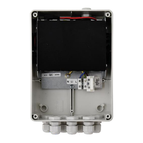
- Page 2 1.2 Block diagram. Fig. 1. Block diagram. 1.3. Description of components and connectors. Table 1. (see Fig.2) Element no. Description (Fig. 2) Pressure Compensator PoE switch Power supply connector of the PSU – L, N Protective connector fuse in the supply circuit (230 V) MAINS Cable glands Fig.
- Page 3 Table 2. (see Fig. 3) Element no. Description (Fig. 2) 2 x UpLink ports 4 x PoE ports (1÷4) DC power supply socket Switch of mode Long Range Fig. 3. The view switch'a. 1.4. Technical parameters.
- Page 4 Table 3. 6 10/100 Mb/s ports (4 x PoE + 2 x UpLink) Ports with connection speed auto-negotiation and MDI/MDIX Auto Cross 3af/at PoE power supply IEEE 802. (1÷4 ports), 52 V DC / 30 W at each port * Protocols, Standards IEEE802.3, 802.3u, 802.3x CSMA/CD, TCP/IP Bandwidth...
- Page 5 The shock protection circuit shall be performed with a particular care, i.e. the yellow and green wire coat of the power cable shall stick to one side of the terminal - marked with ‘ ‘ symbol on the PSU enclosure. Operation of the PSU without the properly made and fully operational shock protection circuit is UNACCEPTABLE! It can cause a device failure or an electric shock.
-
Page 6: Weee Label
Waste electrical and electronic equipment must not be disposed of with normal household waste. According to the European Union WEEE Directive, waste electrical and electronic equipment should be disposed of separately from normal household waste. Pulsar sp. j. Siedlec 150, 32-744 Łapczyca, Poland Tel. (+48) 14-610-19-40, Fax. (+48) 14-610-19-50 e-mail: biuro@pulsar.pl,...
Need help?
Do you have a question about the S64H and is the answer not in the manual?
Questions and answers