Table of Contents
Advertisement
Quick Links
5 10/100 Mb/s ports
4 PoE ports (data transfer and power supply)
15,4W for each PoE port, supports devices complaint
with the IEEE802.3af standard
Supports auto-learning and auto-aging of MAC
addresses (1K size)
Recorder space of dimensions max 400x345x100mm
WxHxD
LED indication
1. Technical description.
1.1. General description.
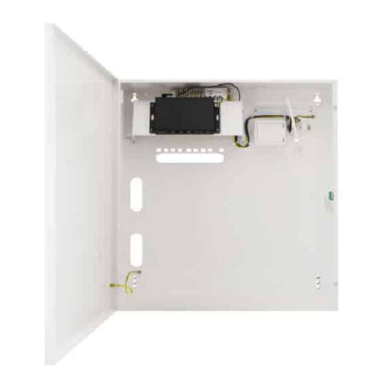
The S54-CR is a complete kit to build the CCTV system based on IP cameras. The switch is placed in a metal enclosure
with recorder space.
Automatic detection of any devices powered in the PoE standard is enabled at the 1 – 4 ports of the switch. The UPLINK port is
used for connection of another network device. The LEDs at the front panel indicate the operation status (description in the table
below). The PoE technology ensures a network connection and reduces installation costs by eliminating the need to supply a
separate power cable for each device. This method allows supplying other network devices, such as IP phone, wireless access
point or router.
S54-CR
v1.1
The S54-CR 5-port switch for 4 IP cameras
in enclosure with recorder space
Edition: 3 from 22.02.2016
Supercedes the edition: 2 from 27.11.2015
Features:
Additional assembly elements (straps for
attaching the DVR in enclosure)
Metal enclosure – color white RAL 9003
warranty – 2 year from the production date
Example of use.
1
PL
EN**
Advertisement
Table of Contents

Related Manuals for Pulsar S54-CR


Summary of Contents for Pulsar S54-CR
- Page 1 1. Technical description. 1.1. General description. The S54-CR is a complete kit to build the CCTV system based on IP cameras. The switch is placed in a metal enclosure with recorder space. Automatic detection of any devices powered in the PoE standard is enabled at the 1 – 4 ports of the switch. The UPLINK port is used for connection of another network device.
- Page 2 1.2 Block diagram. Fig. 1. Block diagram. 1.3. Description of components and connectors. Table 1. (see Fig.2) Element no. Description (Fig. 2) Switch Switch mode power supply for the switch 48VDC/1,2A/60W Potentiometer adjusting the output voltage of the power supply (46÷52V) LED light –...
- Page 3 Table 2. (See Fig.3) Component No. Description (Fig. 3) 4 x PoE port (1÷4) 1 x UPLINK port 48VDC power supply socket Fig. 3 The view switch'a. 1.4. Technical parameters (Table 3.) Table 3. 5 10/100Mb/s ports (4 x PoE + 1 x UPLINK) Ports with connection speed auto-negotiation and MDI/MDIX Auto Cross) PoE power supply...
- Page 4 2. Installation 2.1. Installation procedure 1. The unit should be mounted by a qualified installer, holding relevant permits and licenses (applicable and required for a given country) for 230V/AC interference and low-voltage installations. 2. The unit should be mounted in confined spaces, in accordance with the 2nd environmental class, with normal relative humidity (RH=90% maximum, without condensation) and temperature from -10°C to +45°C.
- Page 5 3. Operation indication (See Table 4). Table 4. Operation indication. OPTICAL INDICATION OF THE SWITCH's POWER SUPPLY GREEN LED LIGHT (Power) OFF – no power supply of the switch Indication of the switch's ON – power supply on, normal operation power supply OPTICAL INDICATION AT THE PoE PORTS (1÷4) DIODA LED ZIELONA (PoE)
- Page 6 GENERAL WARRANTY CONDITIONS 1. Pulsar (manufacturer) grants a two-year quality warranty for the equipment, starting from the production date. 2. The warranty includes free-of-charge repair or replacement with an appropriate equivalent (selected by the manufacturer) if the malfunction is due to the manufacturer.
Need help?
Do you have a question about the S54-CR and is the answer not in the manual?
Questions and answers