Table of Contents
Advertisement
Quick Links
One Technology Way • P.O. Box 9106 • Norwood, MA 02062-9106, U.S.A. • Tel: 781.329.4700 • Fax: 781.461.3113 • www.analog.com
Evaluating the
PACKAGE CONTENTS
ADAU1962/ADAU1966
evaluation board
USBi control interface board
USB cable
D-sub 25-pin to (8) XLR male
12 V desktop supply
OTHER SUPPORTING DOCUMENTATION
ADAU1962
data sheet
ADAU1966
data sheet
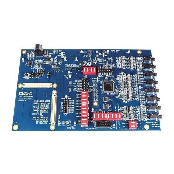
EVALUATION BOARD OVERVIEW
This user guide details the design and setup of the evaluation
board for the ADAU1962/ADAU1966. Because the
is a 12-channel device and the
device, the DAC 13 through DAC 16 outputs do not function
on the
ADAU1962
evaluation board. The evaluation board must
be connected to an external 12 V dc power supply and ground; the
board draws approximately 150 mA.
INTERFACE
PLEASE SEE THE LAST PAGE FOR AN IMPORTANT
WARNING AND LEGAL TERMS AND CONDITIONS.
ADAU1962/ADAU1966
Low Power, Multibit Sigma-Delta DACs
ADAU1962
ADAU1966
is a 16-channel
EVALUATION BOARD DIAGRAM
S/PDIF
INTERFACE
CLOCK
AND
DATA
ROUTING
DSP
Evaluation Board User Guide
High Performance,
On-board regulators derive 9 V, 5 V, and 3.3 V supplies for the
ADAU1962/ADAU1966
ADAU1966
can be controlled through either an I
interface. A small external interface board, EVAL-ADUSB2EBZ,
also called an USBi, connects to a PC USB port and provides
either I
2
C or SPI access to the evaluation board through a ribbon
cable. A graphical user interface (GUI) program, the Automated
Register Window Builder, is provided for easy programming of
the chip in a Microsoft® Windows® PC environment. The
evaluation board allows demonstration and performance testing
of most
ADAU1962/ADAU1966
performance digital-to-analog converter (DAC) operation.
The board has an S/PDIF receiver with RCA and optical
connectors, as well as a discrete serial audio interface that is
available on the Analog Devices, Inc. system development
platform (SDP) interface. Analog outputs are accessible with two
D-sub, 25-pin connectors using the professional audio standard. A
single D-sub, 25-pin to XLR male cable is included with the board
for connecting individual DAC channels to an audio system.
POWER SUPPLY
ADAU1966/
ADAU1962
CONTROL
INTERFACE
Figure 1.
Rev. A | Page 1 of 28
UG-416
and peripherals. The ADAU1962/
2
C or SPI
features, including high
DAC 9 TO
DAC 16
DAC 1 TO
DAC 8
Advertisement
Table of Contents

Related Manuals for Analog Devices ADAU1962


Summary of Contents for Analog Devices ADAU1962
-
Page 1: Package Contents
12-channel device and the ADAU1966 is a 16-channel available on the Analog Devices, Inc. system development device, the DAC 13 through DAC 16 outputs do not function platform (SDP) interface. Analog outputs are accessible with two on the ADAU1962 evaluation board. -
Page 2: Table Of Contents
Digital Audio Connections and Routing ........7 Standalone Mode ................3 Connecting Analog Audio Cables ..........8 C and SPI Control ..............4 Using the ADAU1962/ADAU1966 ..........8 Automated Register Window Builder Software Installation .. 4 Schematics and Artwork ..............9 Hardware Setup—USBi ............... 4 REVISION HISTORY 1/14—Rev. -
Page 3: Setting Up The Evaluation Board
Figure 2. Pin 42 is pulled high (1) and Pin 43 to Pin 45 are JP21, as shown in Figure 2, pulls SA_MODE (Pin 46) high, pulled low (0). According to Table 1, this puts the ADAU1962/ enabling the standalone mode in the ADAU1962/ADAU1966. -
Page 4: I 2 C And Spi Control
AUTOMATED REGISTER WINDOW BUILDER SOFTWARE INSTALLATION The evaluation board can be configured for live control over the registers in the ADAU1962/ADAU1966. When the The Automated Register Window Builder is a program that Automated Register Window Builder software is installed launches a graphical interface for direct, live control of the... -
Page 5: Powering The Board
RESET FOR THE EVALUATION BOARD ADAU1962/ADAU1966 evaluation board has provision for resetting and powering down the ADAU1962/ADAU1966. S2 on the evaluation board, shown in Figure 9, is a momentary reset switch that pulls the master reset ( MR ) line low; this line controls the reset generator U10. -
Page 6: Setting Up The Master Clock (Mclk)
MCLKO pin of the ADAU1962/ADAU1966. To route MCLK from the SDP interface to the ADAU1962/ ADAU1966, apply a shorting jumper across JP6 (MCLK_SEL), as shown in Figure 12; this sets the direction of the level... -
Page 7: Pll Selection
Figure 17. S/PDIF Data and Clock Routing The SDP interface, J6 and J8, make up a standard interconnect within Analog Devices. They provide for transfer of digital audio, clocks, and control between boards. For additional information, see the pinout included in the schematic in Figure 28. -
Page 8: Connecting Analog Audio Cables
CONNECTING ANALOG AUDIO CABLES If the ADAU1962/ADAU1966 are not powered up in There are two forms of the analog outputs of the ADAU1962/ standalone mode, the USBi must be connected to set the ADAU1966 evaluation board: differential outputs and single- appropriate registers to make the part operational. -
Page 9: Schematics And Artwork
Evaluation Board User Guide UG-416 SCHEMATICS AND ARTWORK Figure 21. ADAU1962/ADAU1966 Evaluation Board Block Diagram Schematic, Page 1 Rev. A | Page 9 of 28... - Page 10 UG-416 Evaluation Board User Guide Figure 22. ADAU1962/ADAU1966 Evaluation Board, PLL LF Selection and Internal Regulator Schematic, Page 2 Rev. A | Page 10 of 28...
- Page 11 Evaluation Board User Guide UG-416 Figure 23. ADAU1962/ADAU1966 Evaluation Board, DAC Outputs, CH1 and CH2 Active Buffer and CH1 to CH4 Passive Filters Schematic, Page 3 Rev. A | Page 11 of 28...
- Page 12 UG-416 Evaluation Board User Guide Figure 24. ADAU1962/ADAU1966 Evaluation Board, RC Output Filters and D-Sub 25-Pin Connectors Schematic, Page 4 Rev. A | Page 12 of 28...
- Page 13 Evaluation Board User Guide UG-416 Figure 25. ADAU1962/ADAU1966 Evaluation Board, BCLK, LRCLK, and SDATA Jumpers and Routing Schematic, Page 5 Rev. A | Page 13 of 28...
- Page 14 UG-416 Evaluation Board User Guide Figure 26. ADAU1962/ADAU1966 Evaluation Board, MCLK Source, USBi Interface, CLKOUT Feed, and Reset Generator Schematic, Page 6 Rev. A | Page 14 of 28...
- Page 15 Evaluation Board User Guide UG-416 Figure 27. ADAU1962/ADAU1966 Evaluation Board, Level Shift and Clock Direction Control Schematic, Page 7 Rev. A | Page 15 of 28...
- Page 16 UG-416 Evaluation Board User Guide Figure 28. ADAU1962/ADAU1966 Evaluation Board, SDP Interface Connectors Schematic, Page 8 Rev. A | Page 16 of 28...
- Page 17 Evaluation Board User Guide UG-416 Figure 29. ADAU1962/ADAU1966 Evaluation Board, S/PDIF Receiver Schematic, Page 9 Rev. A | Page 17 of 28...
- Page 18 UG-416 Evaluation Board User Guide Figure 30. ADAU1962/ADAU1966 Evaluation Board, Power Supply Schematic, Page 10 Rev. A | Page 18 of 28...
- Page 19 Evaluation Board User Guide UG-416 Figure 31. ADAU1962/ADAU1966 Evaluation Board, Top Assembly Rev. A | Page 19 of 28...
- Page 20 UG-416 Evaluation Board User Guide Figure 32. ADAU1962/ADAU1966 Evaluation Board, Top Layer Copper Rev. A | Page 20 of 28...
- Page 21 Evaluation Board User Guide UG-416 Figure 33. ADAU1962/ADAU1966 Evaluation Board, L2 Ground Rev. A | Page 21 of 28...
- Page 22 UG-416 Evaluation Board User Guide Figure 34. ADAU1962/ADAU1966 Evaluation Board, L3 Power Rev. A | Page 22 of 28...
- Page 23 Evaluation Board User Guide UG-416 Figure 35. ADAU1962/ADAU1966 Evaluation Board, Bottom Copper Rev. A | Page 23 of 28...
- Page 24 UG-416 Evaluation Board User Guide Figure 36. ADAU1962/ADAU1966 Evaluation Board, Bottom Assembly Rev. A | Page 24 of 28...
- Page 25 Evaluation Board User Guide UG-416 NOTES Rev. A | Page 25 of 28...
- Page 26 UG-416 Evaluation Board User Guide NOTES Rev. A | Page 26 of 28...
- Page 27 Evaluation Board User Guide UG-416 NOTES Rev. A | Page 27 of 28...
- Page 28 By using the evaluation board discussed herein (together with any tools, components documentation or support materials, the “Evaluation Board”), you are agreeing to be bound by the terms and conditions set forth below (“Agreement”) unless you have purchased the Evaluation Board, in which case the Analog Devices Standard Terms and Conditions of Sale shall govern. Do not use the Evaluation Board until you have read and agreed to the Agreement.
Need help?
Do you have a question about the ADAU1962 and is the answer not in the manual?
Questions and answers