Table of Contents
Advertisement
Quick Links
One Technology Way • P.O. Box 9106 • Norwood, MA 02062-9106, U.S.A. • Tel: 781.329.4700 • Fax: 781.461.3113 • www.analog.com
Evaluating the ADAU1772 using the EVAL-ADAU1772Z
EVAL-ADAU1772Z PACKAGE CONTENTS
ADAU1772 evaluation board
EVAL-ADUSB2EBZ (USBi) communications adapter
USB cable with Mini-B plug
Evaluation board/software quick-start guide
DOCUMENTS NEEDED
ADAU1772
data sheet
AN-1006
Applications Note, Using the EVAL-ADUSB2EBZ
GENERAL DESCRIPTION
This user guide explains the design and setup of the ADAU1772
evaluation board.
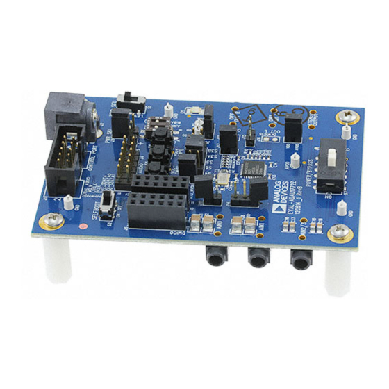
Figure 1. Evaluation Board Top Side
PLEASE SEE THE LAST PAGE FOR AN IMPORTANT
WARNING AND LEGAL TERMS AND CONDITIONS.
EVALUATION BOARD TOP SIDE AND BOTTOM SIDE
Rev. 0 | Page 1 of 27
Evaluation Board User Guide
This evaluation board provides full access to all analog and digital
I/Os on the ADAU1772. The ADAU1772 core is controlled by
Analog Devices, Inc., SigmaStudio™ software, which interfaces to
the board via a USB connection. This evaluation board can be
powered by a single AAA battery, by the USB bus, or by a single
3.8 V to 6 V supply; any of these are regulated to the voltages
required on the board. The PC board is a 4-layer design, with a
single ground plane and a single power plane on the inner layers.
The board contains connectors for external microphones and
speakers. The master clock can be provided externally or by the
on-board 12.288 MHz passive crystal.
Figure 2. Evaluation Board Bottom Side
UG-XXX
Advertisement
Table of Contents

Related Manuals for Analog Devices ADAU1772


Summary of Contents for Analog Devices ADAU1772
-
Page 1: Eval-Adau1772Z Package Contents
The master clock can be provided externally or by the GENERAL DESCRIPTION on-board 12.288 MHz passive crystal. This user guide explains the design and setup of the ADAU1772 evaluation board. EVALUATION BOARD TOP SIDE AND BOTTOM SIDE Figure 2. Evaluation Board Bottom Side Figure 1. -
Page 2: Table Of Contents
Evaluation Board User Guide UG-XXX One Technology Way • P.O. Box 9106 • Norwood, MA 02062-9106, U.S.A. • Tel: 781.329.4700 • Fax: 781.461.3113 • www.analog.com Evaluating the ADAU1772 using the EVAL-ADAU1772Z TABLE OF CONTENTS EVAL-ADAU1772Z Package Contents .......... 1 Power ....................9... -
Page 3: Evaluation Board Block Diagrams
POWER / SUPPLY COMMUNICATIONS BYPASS REGULATION HEADER SWITCH SELFBOOT EEPROM MP PINS ANALOG MIC INPUTS STEREO LINE ADAU1772 INPUT DIFFERENTIAL STEREO OUTPUT DIGITAL MIC INPUTS SINGLE-ENDED SERIAL AUDIO STEREO OUTPUT CONNECTOR MASTER CLOCK XTAL OSCILLATOR Figure 3. Functional Block Diagram... - Page 4 UG-177 Evaluation Board User Guide Figure 5. Default Jumper and Switch Settings (A Solid Black Rectangle Indicates a Switch or Jumper Position) Rev. 0 | Page 4 of 27...
-
Page 5: Setting Up The Evaluation Board
Evaluation Board User Guide UG-177 SETTING UP THE EVALUATION BOARD INSTALLING THE SigmaStudio SOFTWARE Click Search for the best driver in these locations, select Include this location in the search, and click Browse to find Users can download the latest version of SigmaStudio by the SigmaStudio 3.7.x\USB drivers directory (see Figure 8). -
Page 6: Default Switch And Jumper Settings
For normal operation the switch should be slid Figure 12. USBi Not Detected by SigmaStudio to the left. S1 selects whether the ADAU1772 is to be powered If SigmaStudio detects the USBi on the USB port of the computer, from 3.3 V or 1.8 V, the default is 3.3 V. -
Page 7: Creating A Basic Signal Flow
Evaluation Board User Guide UG-177 CREATING A BASIC SIGNAL FLOW To access the Schematic tab, where a signal processing flow can be created, click the Schematic tab at the top of the screen (see Figure 16). Figure 16. Schematic Tab The left side of the schematic view includes the Toolbox, which contains all of the algorithms that can run in the SigmaDSP. -
Page 8: Downloading The Program To The Dsp
Figure 26. Pin/Pad Control tab Navigate to the Hardware Configuration. In the bottom left Your schematic is ready to be compiled and downloaded to the corner you will see the IC 1 – ADAU1772 Register Control tab evaluation board. (see Figure 24). -
Page 9: Using The Evaluation Board
S1, for the on-board circuitry. LED D1 lights up Microphone Bias when power is supplied to the board. To connect power to the ADAU1772, connect the J8, J10, J12, and J17 jumpers (see To add MICBIAS0 to AIN0, connect a jumper to header J11. Figure 30). - Page 10 UG-177 Evaluation Board User Guide Figure 34. Clock Output Enabled/Divided Now, set the input of the ADAU1772 to be the digital microphones instead of the ADCs by toggling the appropriate Figure 32. Mic Bias Enable and Gain Decimator Source settings. Navigate to the PGA/ADC tab to Stereo Line Input find and set the following switches (See Figure 35).
-
Page 11: Mp Pins
MP PINS The MP PIN JUMPERS header J9 provides access to MP pins MP0, MP1, MP2, MP3, and MP6 of the ADAU1772, as well as facilitates the use of the push buttons on the EVAL- ADAU1772Z board. See Figure 46 for the pin-out of the header. -
Page 12: Power-Down
Compilation to E2PROM” (see Figure 41). of the board, provides access to the power-down pin on the ADAU1772. Put a jumper on the header to power down all analog and digital circuits. Before enabling /PD be sure to mute the outputs to avoid any pops or clicks when the IC is powered down. -
Page 13: Hardware Description
MP Pin Jumpers Jumpers used to connect pushbuttons on the board to MP Pins on the ADAU1772. IOVDD VDD Jumper connects IOVDD on the ADAU1772 to VDD (3.3 V board supply) on the evaluation board. J11, J14 Microphone Bias Jumpers used to add a mic bias to the analog mic inputs AIN0 and AIN1. -
Page 14: Evaluation Board Schematics And Artwork
UG-177 Evaluation Board User Guide EVALUATION BOARD SCHEMATICS AND ARTWORK Figure 43. Evaluation Board Schematic—Digital and Analog I/O, Master Clock Generation Rev. 0 | Page 14 of 27... - Page 15 Evaluation Board User Guide UG-177 PDM Digital Microphone Inputs IOVDD DMIC_0_1 10k0 ADC_SDATA1/CLKOUT/MP6 10k0 POLARIZINGPLUG POLARIZINGPLUG 100R SOCKET_12WAY_UNSHROUD IOVDD DMIC_2_3 10k0 10k0 ADC_SDATA1/CLKOUT/MP6 POLARIZINGPLUG POLARIZINGPLUG 100R SOCKET_12WAY_UNSHROUD Figure 44. Evaluation Board Schematic—PDM Digital Microphone Interface Serial Audio Interface HEADER_12WAY_UNSHROUD EXT_MCLK LRCLK/MP3 49R9 BCLK/MP2...
- Page 16 UG-177 Evaluation Board User Guide USB_5V 2.2uH IOVDD PWR SEL ADP1713AUJZ-1.5-R7 USB/EXT ADP1607ACPZ-R7 EXT_5V VOUT BATT RAPC722X 10k0 VDD SEL 162k 0.10uF 0.10uF 100R 10nF BRD_RESET 10uF 137k 10uF SPDT 0.10uF 0.10uF 0.10uF 0.10uF 10uF Green Diffused 0.10uF 374k Battery Input 1.5 V Maximum Plane Decoupling Figure 47.
- Page 17 Evaluation Board User Guide UG-177 Figure 49. Evaluation Board Layout—Top Assembly Rev. 0 | Page 17 of 27...
- Page 18 UG-177 Evaluation Board User Guide Figure 50. Evaluation Board Layout—Top Copper Rev. 0 | Page 18 of 27...
- Page 19 Evaluation Board User Guide UG-177 Figure 51. Evaluation Board Layout—Power Plane Rev. 0 | Page 19 of 27...
- Page 20 UG-177 Evaluation Board User Guide Figure 52. Evaluation Board Layout—Ground Plane Rev. 0 | Page 20 of 27...
- Page 21 Evaluation Board User Guide UG-177 Figure 53. Evaluation Board Layout—Bottom Copper Rev. 0 | Page 21 of 27...
- Page 22 UG-177 Evaluation Board User Guide Figure 54. Evaluation Board Layout—Bottom Assembly Rev. 0 | Page 22 of 27...
-
Page 23: Ordering Information
CRYSTAL 12.288 MHZ SMT 18PF ABM3B-12.288MHZ-10- Abracon Corp 1-U-T ADAU1772 4 ADC 2 DAC ANC Codec ADAU1772 Analog Devices ADP1607ACPZ- Synchronous Boost DC/DC Converter ADP1607ACPZ-R7 Analog Devices Inc ADP1713AUJZ- Fixed Low-Dropout Voltage Inc. ADP1713AUJZ-1.5-R7 Rev. 0 | Page 23 of 27... -
Page 24: Related Links
Tact Switch Long Stroke (normally B3M-6009 Omron Electronics open) TP1-7 5002 Mini Test Point White .1" OD 5002 Keystone Electronics RELATED LINKS Resource Description ADAU1772 Product Page, 4 ADC, 2 DAC Low-Power Codec with Audio Processor Rev. 0 | Page 24 of 27... - Page 25 Evaluation Board User Guide UG-177 NOTES Rev. 0 | Page 25 of 27...
- Page 26 By using the evaluation board discussed herein (together with any tools, components documentation or support materials, the “Evaluation Board”), you are agreeing to be bound by the terms and conditions set forth below (“Agreement”) unless you have purchased the Evaluation Board, in which case the Analog Devices Standard Terms and Conditions of Sale shall govern. Do not use the Evaluation Board until you have read and agreed to the Agreement.
- Page 27 Evaluation Board User Guide UG-177 Rev. 0 | Page 27 of 27...
Need help?
Do you have a question about the ADAU1772 and is the answer not in the manual?
Questions and answers