Table of Contents
Advertisement
Quick Links
One Technology Way • P.O. Box 9106 • Norwood, MA 02062-9106, U.S.A. • Tel: 781.329.4700 • Fax: 781.461.3113 • www.analog.com
FEATURES
Ready SPI interface for setup and control
Easy connection to test equipment
EVALUATION KIT CONTENTS
ADA8282CP-EBZ
6 V, 2 A switching power source
EQUIPMENT NEEDED
PC running Windows®
USB 2.0 port
SDP-B
SOFTWARE NEEDED
Analysis control evaluation (ACE) software
PLEASE SEE THE LAST PAGE FOR AN IMPORTANT
WARNING AND LEGAL TERMS AND CONDITIONS.
Arrow.com.
Downloaded from
Evaluating the
evaluation board
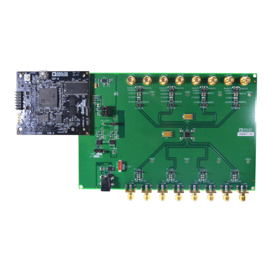
DIGITAL PICTURE OF THE BOARD
ADA8282CP-EBZ User Guide
ADA8282
Radar Receive Path AFE
GENERAL DESCRIPTION
The
ADA8282CP-EBZ
the
ADA8282
board connects to the system demonstration platform (SDP) for
easy configuration of registers through a serial peripheral
interface (SPI) using the ACE evaluation software. The board
provides headers to allow configuration using other platforms.
It also includes on-board options to provide manual reset
capability to the part.
This user guide provides quick start instructions for working
with the board.
Full specifications for the
data sheet, which should be consulted in conjunction with this
user guide when using the evaluation board.
Figure 1.
Rev. 0 | Page 1 of 16
is designed to aid in the evaluation of
radar receive path analog front-end (AFE). The
ADA8282
are available in the product
UG-846
Advertisement
Table of Contents

Subscribe to Our Youtube Channel
Related Manuals for Analog Devices ADA8282CP-EBZ


Summary of Contents for Analog Devices ADA8282CP-EBZ
-
Page 1: Features
ADA8282CP-EBZ User Guide UG-846 One Technology Way • P.O. Box 9106 • Norwood, MA 02062-9106, U.S.A. • Tel: 781.329.4700 • Fax: 781.461.3113 • www.analog.com Evaluating the ADA8282 Radar Receive Path AFE FEATURES GENERAL DESCRIPTION ADA8282CP-EBZ is designed to aid in the evaluation of... -
Page 2: Table Of Contents
UG-846 ADA8282CP-EBZ User Guide TABLE OF CONTENTS Features ....................1 Jumper Configurations ..............3 Evaluation Kit Contents ..............1 Evaluation Board Software Quick Start Procedures .....4 Equipment Needed ................1 Evaluation Board Software ............4 Software Needed ................1 Quick Start Procedures ..............4 General Description ................. -
Page 3: Evaluation Board Hardware
ADA8282CP-EBZ User Guide UG-846 EVALUATION BOARD HARDWARE POWER SUPPLY The inputs of the ADA8282 are intended to be driven by a differential signal source. The output signal swing is reduced by ADA8282CP-EBZ comes with a wall-mountable switching a factor of 2 when driven by a single-ended source. -
Page 4: Evaluation Board Software Quick Start Procedures
QUICK START PROCEDURES Figure 6 shows the typical evaluation board setup for the Figure 4. ADA8282 ACE Board View ADA8282CP-EBZ. Complete the following steps to enable functionality testing of the part: Double-click the ADA8282 component on the board to navigate to the chip view (see Figure 5). Click the tabs to Configure the jumpers as shown in Figure 2. -
Page 5: Configuring The Ada8282 Through Ace
ADA8282CP-EBZ User Guide UG-846 To read from the device, complete the following steps: CONFIGURING THE ADA8282 THROUGH ACE Select the address from the Address drop-down menu, The ACE software provides several views or interfaces for Click Read (see Figure 9). -
Page 6: Using The Ace Memory Map
UG-846 ADA8282CP-EBZ User Guide To manipulate the gain of a channel, type in the desired gain on USING THE ACE MEMORY MAP the corresponding channel that should be changed in the PGA The memory map for the ADA8282 can be accessed by clicking section. -
Page 7: Ada8282 Register Summary
ADA8282CP-EBZ User Guide UG-846 ADA8282 REGISTER SUMMARY The register settings for the ADA8282 are given in the register section of the ADA8282 data sheet. An abbreviated register summary is shown in Table 2. Table 2. ADA8282 Register Summary Register Address... -
Page 8: Evaluation Board Schematics And Artwork
UG-846 ADA8282CP-EBZ User Guide EVALUATION BOARD SCHEMATICS AND ARTWORK +JINA AGND C1INA +INA P1INA 0.1µF C2INA –INA –JINA 0.1µF AGND AGND +JINB C1INB AGND +INB P1INB 0.1µF C2INB –INB –JINB 0.1µF AGND AGND +JINC AGND C1INC +INC P1INC 0.1µF C2INC –INC... - Page 9 ADA8282CP-EBZ User Guide UG-846 C2OUTA +JOUTA R1OUTA +OUTA P2OUTA 0.1µF P1OUTA C3OUTA –JOUTA R2OUTA –OUTA 0.1µF AGND AGND AGND AGND C2OUTB +JOUTB R1OUTB +OUTB P2OUTB 0.1µF P1OUTB C3OUTB –JOUTB R2OUTB –OUTB 0.1µF AGND AGND AGND AGND C2OUTC +JOUTC R1OUTC +OUTC...
- Page 10 UG-846 ADA8282CP-EBZ User Guide 0.1µF 0.1µF 0.1µF AGND +INA +OUTA +INA +OUTA –INA OUTA –INA –OUTA +INB +OUTB +INB +OUTB –INB OUTB –INB –OUTB +INC +OUTC +INC +OUTC –INC OUTC –INC –OUTC +IND +OUTD +IND +OUTD –IND OUTD –IND –OUTD...
- Page 11 ADA8282CP-EBZ User Guide UG-846 Figure 18. Power Section Schematic Rev. 0 | Page 11 of 16 Arrow.com. Arrow.com. Arrow.com. Arrow.com. Arrow.com. Arrow.com. Arrow.com. Arrow.com. Arrow.com. Arrow.com. Arrow.com. Downloaded from Downloaded from Downloaded from Downloaded from Downloaded from Downloaded from Downloaded from...
- Page 12 UG-846 ADA8282CP-EBZ User Guide THE SDP CONNECTOR IMPLEMENTS THE E13 CONNECTOR SPECIFICATIONS STANDARD. THIS IS A STANDARD FOR USE ACROSS ADI AND CANNOT BE MODIFIED 3.3V 0.1µF 10µF 100kΩ 100kΩ R0603 DGND R0603 24LC32A-I/ST TOL=1 TSSOP8 RESET_IN_N BMODE1 DGND UART_RX UART_TX 100kΩ...
- Page 13 ADA8282CP-EBZ User Guide UG-846 Figure 20. Evaluation Board Layout, Layer 1 Figure 21. Evaluation Board Layout, Layer 2 Rev. 0 | Page 13 of 16 Arrow.com. Arrow.com. Arrow.com. Arrow.com. Arrow.com. Arrow.com. Arrow.com. Arrow.com. Arrow.com. Arrow.com. Arrow.com. Arrow.com. Arrow.com. Downloaded from...
- Page 14 UG-846 ADA8282CP-EBZ User Guide Figure 22. Evaluation Board Layout, Layer 3 Figure 23. Evaluation Board Layout, Layer 4 Rev. 0 | Page 14 of 16 Arrow.com. Arrow.com. Arrow.com. Arrow.com. Arrow.com. Arrow.com. Arrow.com. Arrow.com. Arrow.com. Arrow.com. Arrow.com. Arrow.com. Arrow.com. Arrow.com. Downloaded from...
-
Page 15: Ordering Information
ADA8282CP-EBZ User Guide UG-846 ORDERING INFORMATION BILL OF MATERIALS Table 3. Item Reference Designator Description Manufacturer Part Number IC 32 kB serial EEPROM Microchip Technology 24LC32A-I/ST 500 mA, low noise regulator Analog Devices, Inc. ADP7105ARDZ-5.0 Low noise linear regulator Analog Devices, Inc. - Page 16 By using the evaluation board discussed herein (together with any tools, components documentation or support materials, the “Evaluation Board”), you are agreeing to be bound by the terms and conditions set forth below (“Agreement”) unless you have purchased the Evaluation Board, in which case the Analog Devices Standard Terms and Conditions of Sale shall govern. Do not use the Evaluation Board until you have read and agreed to the Agreement.
Need help?
Do you have a question about the ADA8282CP-EBZ and is the answer not in the manual?
Questions and answers