Table of Contents
Advertisement
Quick Links
One Technology Way • P.O. Box 9106 • Norwood, MA 02062-9106, U.S.A. • Tel: 781.329.4700 • Fax: 781.461.3113 • www.analog.com
Evaluating the
AD5758
FEATURES
Full featured evaluation board for the
On-board 2.5 V
ADR4525
reference
SPI
ACE
software for control
EVALUATION KIT CONTENTS
EVAL-AD5758SDZ evaluation board
EVAL-SDP-CS1Z
EQUIPMENT NEEDED
EVAL-SDP-CS1Z
Bench top power supply and connector cables
DOCUMENTS NEEDED
AD5758
data sheet
EVAL-AD5758SDZ evaluation board user guide
ACE User Manual
SOFTWARE NEEDED
ACE
software for control
PLEASE SEE THE LAST PAGE FOR AN IMPORTANT
WARNING AND LEGAL TERMS AND CONDITIONS.
Single-Channel, 16-Bit Current and Voltage Output DAC with
Dynamic Power Control and HART Connectivity
AD5758
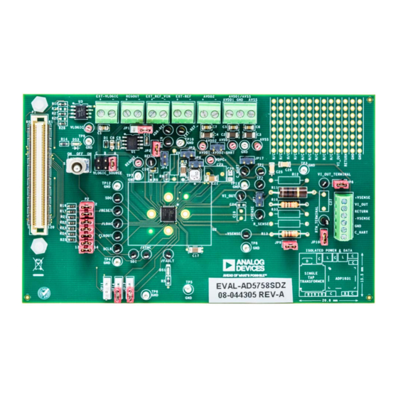
EVALUATION BOARD PHOTOGRAPH
EVAL-AD5758
GENERAL DESCRIPTION
This user guide describes the evaluation board for the AD5758,
a functional safety certified, single-channel, voltage and current
output, digital-to-analog converter (DAC) with on-chip dynamic
power control (DPC) that minimizes package power dissipation.
For full details on the AD5758, refer to the
Consult the data sheet when using the EVAL-AD5758SDZ. The
configuration of the various link options is explained in the
Evaluation Board Hardware section. The installation of the
companion software is discussed in the Software Quick Start
Procedures section.
The EVAL-AD5758SDZ, shown in Figure 1, requires the
SDP-CS1Z
board. The EVAL-AD5758SDZ interfaces to the USB
port of the PC via the
allows the user to easily program the AD5758, namely the
Analysis|Control|Evaluation (ACE)
the EVAL-AD5758SDZ.
Figure 1.
Rev. 0 | Page 1 of 20
User Guide
AD5758
EVAL-SDP-CS1Z
board. Software that
software, is available with
UG-1268
data sheet.
EVAL-
Advertisement
Table of Contents

Related Manuals for Analog Devices AD5758


Summary of Contents for Analog Devices AD5758
-
Page 1: Features
Dynamic Power Control and HART Connectivity FEATURES GENERAL DESCRIPTION Full featured evaluation board for the AD5758 This user guide describes the evaluation board for the AD5758, On-board 2.5 V ADR4525 reference a functional safety certified, single-channel, voltage and current output, digital-to-analog converter (DAC) with on-chip dynamic software for control power control (DPC) that minimizes package power dissipation. -
Page 2: Table Of Contents
Serial Communication ..............3 Events Tool .................. 12 AD5758 Device Under Test (DUT) Address Pins ......3 Evaluation Board Schematics and Artwork ........ 13 Software Quick Start Procedures ............ 5 Ordering Information ..............19 ... -
Page 3: Evaluation Board Hardware
LOGIC be selected from 3.3V_SDP, V , or EXT-VLOGIC through the monitors the FAULT pin of the AD5758. VLOGIC_SOURCE link. See Table 1 for more link options. See The EVAL-AD5758SDZ evaluation board has the option to Table 3 for the default link positions. - Page 4 UG-1268 EVAL-AD5758 User Guide Table 2. Link Options for Link P2 Pin No. Position Function 1, 2 Inserted Connects the FAULT signal from the SDP-S to the FAULT pin on the AD5758 Not inserted Disconnects the FAULT signal from the...
-
Page 5: Software Quick Start Procedures
To set up the EVAL-AD5758SDZ, take the following steps: PLUG-INS Connect a USB cable to the PC and then to the EVAL-SDP- The EVAL-AD5758SDZ software uses the Analog Devices, Inc., CS1Z (SDP-S). software. For instructions on how to install and use the... - Page 6 A new window appears as shown in Figure 5. Find the Double-click EVAL-AD5758SDZ to open the AD5758 Board.AD5758 plug-in and click the Install Selected button. block diagram (see Figure 7). The INITIAL CONFIG- The EVAL-AD5758SDZ plug-in is now installed and is URATION menu appears on the left.
-
Page 7: Ad5758 Block Diagram And Functions
EVAL-AD5758 User Guide UG-1268 AD5758 BLOCK DIAGRAM AND FUNCTIONS AD5758 ACE plug-in is organized so that it appears similar A full description of each block and register setting is available to the block diagram shown in the AD5758 data sheet. In this... - Page 8 GUI access on several registers. Pop-ups, drop-down menus, and hexadecimal textboxes are available in the GUI to configure several registers of the AD5758. To write the changes to the device, the Apply Changes button (Label A) must be clicked. The functions within the GUI that control various registers (Label L1 through Label L15) are described in Table 5.
-
Page 9: Initial Configuration
EVAL-AD5758 User Guide UG-1268 Figure 9. AD5758 Memory Map in the Software INITIAL CONFIGURATION An initial configuration wizard is available when opening the AD5758 plug-in. The initial configuration wizard allows quick configuration of the AD5758 and provides configuration of the clock output in the general-purpose configuration register, the dc-to-dc settings, DAC configuration, and the DAC input register. -
Page 10: Setting The Dac Output
UG-1268 EVAL-AD5758 User Guide SETTING THE DAC OUTPUT WRITING TO THE ADC CONFIGURATION REGISTER To configure the DAC output, use the pop-up menu for the DAC The procedure to set up and configure the ADC sequencer is configuration register (see Figure 11), available in the GUI. Click... -
Page 11: Example Sequences
To return to the main There are several example sequences available. Click the Example window, click the Back to the AD5758 button. Sequences button and the window shown in Figure 15 appears. To enable any of the sequences, click on the relevant sequence Figure 15. -
Page 12: Ace Tool Views
UG-1268 EVAL-AD5758 User Guide TOOL VIEWS software provides additional functionality to the main REGISTER DEBUGGER TOOL view described in this user guide Open these views from the view Use the register debugger tool to perform raw writes to and menu item on the application toolbar. -
Page 13: Evaluation Board Schematics And Artwork
EVAL-AD5758 User Guide UG-1268 EVALUATION BOARD SCHEMATICS AND ARTWORK TESTPOINTS: REGOUT 1727010 RED = POWER WHITE = GROUND BLACK = SIGNAL USE FOOTPRINT THAT CAN ACCOMMODATE 120/0805/0603 ON C21 OPTION TO DRIVE VDPC+ WITH AVDD1 (BYPASS POSITIVE DC-DC) 69157-102 REGOUT_ VDPC+ 0.1UF... - Page 14 0.1UF 1727010 C0805H53 VLOGIC EXT-VLOGIC EXT-VLOGIC 0.1UF 1727010 C0805H53 VLOGIC SOURCE OPTIONS VLOGIC_SOURCE 3.3V_SDP VLDO VLOGIC EXT-VLOGIC 2213S-06G AD5758 REFIN OPTIONS ADR-REF ADR-REF REFIN 69157-102 EXT-REF_ REFGND REFIN EXT-REF 69157-102 REFOUT REFOUT 69157-102 AVDD2 ADR-REF VIN = 3V - 15V...
- Page 15 EVAL-AD5758 User Guide UG-1268 3.3V_SDP 100K 3.3V_SDP 100K RESET_IN_N BMODE1 UART_RX UART_TX 100K RESET_OUT_N SLEEP_N 24LC32A/SN EEPROM_A0 WAKE_N SDP DEBUG LED CLKOUT TMR_C TMR_D TMR_A TMR_B GPIO6 GPIO7 GPIO4 GPIO5 /FAULT_SDP GPIO2 GPIO3 GPIO0 GPIO1 /LDAC_SDP /RESET_SDP SCL_1 SCL_0 SDA_1...
- Page 16 UG-1268 EVAL-AD5758 User Guide VIOUT_INT +VSENSE THROUGH-HOLE COMPONENTS USED FOR SERIES RESIS TORS +VSENSE VI_OUT VI_OUT_TERMINAL +VSENSE VI_OUT_TERMINAL VI_OUT VI_OUT RTN_TERMINAL RETURN -VSENSE 10000PF PLACEHOLDER TO EXPERIMENT WITH SETTLING TIME C_HART 1725698 RTN_TERMINAL THROUGH-HOLE LOAD RESISOR OPTION IN GOLD PINS...
- Page 17 EVAL-AD5758 User Guide UG-1268 Figure 21. Silkscreen Figure 22. Layer 1 Rev. 0 | Page 17 of 20...
- Page 18 UG-1268 EVAL-AD5758 User Guide Figure 23. Ground and Power Plane, Layer 2 and Layer 3 Figure 24. Layer 4 (Secondary) Rev. 0 | Page 18 of 20...
-
Page 19: Ordering Information
EVAL-AD5758 User Guide UG-1268 ORDERING INFORMATION BILL OF MATERIALS Table 6. Bill of Materials Reference Designator Description Manufacturer Part Number +VSENSE, −VSENSE, /FAULT, /LDAC, /RESET, Black test points Components Corporation TP-104-01-00 /SYNC, ADR-REF, CLKOUT,CHART,EXT-REF, REFIN, REFOUT, RTN_TERMINAL, SCLK, SDI, SDO, TP1, TP2, VIOUT, VI_OUT_TERMINAL... - Page 20 By using the evaluation board discussed herein (together with any tools, components documentation or support materials, the “Evaluation Board”), you are agreeing to be bound by the terms and conditions set forth below (“Agreement”) unless you have purchased the Evaluation Board, in which case the Analog Devices Standard Terms and Conditions of Sale shall govern. Do not use the Evaluation Board until you have read and agreed to the Agreement.
Need help?
Do you have a question about the AD5758 and is the answer not in the manual?
Questions and answers