Table of Contents
Advertisement
Quick Links
One Technology Way • P.O. Box 9106 • Norwood, MA 02062-9106, U.S.A. • Tel: 781.329.4700 • Fax: 781.461.3113 • www.analog.com
Evaluation Board for the
EVALUATION BOARD FEATURES
Easy to use evaluation board
Simple, in-phase (I) and quadrature (Q) demodulation in a
single channel
Differential or single-ended input/output
USB powered
On-board oscillator
EEPROM programmable option
Synchronization signals available for external devices
GENERAL DESCRIPTION
This user guide describes the evaluation board that contains the
Analog Devices, Inc.,
ADA2200
demodulator. The circuit configurations available through the
ADA2200-EVALZ
enable the user to exercise its full set of features.
The
ADA2200-EVALZ
simplifies signal connections to standard
test equipment. Inputs, outputs, supplies, and other circuit test
PLEASE SEE THE LAST PAGE FOR AN IMPORTANT
WARNING AND LEGAL TERMS AND CONDITIONS.
ADA2200
sampled analog, synchronous
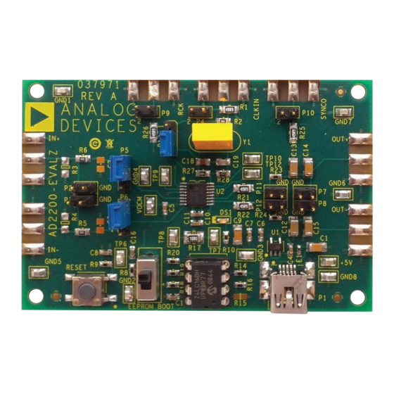
EVALUATION BOARD PHOTOGRAPH
ADA2200-EVALZ User Guide
Synchronous Demodulator
points can be easily accessed via test clips, differential probes, or
standard SMA cables. In addition, the board can be easily powered
from any USB port through the included USB cable.
The
ADA2200-EVALZ
measurements on the signals applied to its inputs. The selection
between I and Q components is accomplished with a simple
toggle switch.
The recommended configuration for initial evaluation is shown
in Figure 2. See the Quick Start and Setup Procedure section for
more details.
Complete specifications for the
ADA2200
data sheet, which must be consulted in conjunction with
this user guide when using the evaluation board. The data sheet
and user guide are available to download from the
the
ADA2200-EVALZ
Figure 1.
Rev. 0 | Page 1 of 10
performs amplitude and phase
ADA2200
are available in the
ADA2200
product pages at www.analog.com.
UG-702
and
Advertisement
Table of Contents

Subscribe to Our Youtube Channel
Related Manuals for Analog Devices ADA2200-EVALZ


Summary of Contents for Analog Devices ADA2200-EVALZ
-
Page 1: Evaluation Board Features
ADA2200-EVALZ User Guide UG-702 One Technology Way • P.O. Box 9106 • Norwood, MA 02062-9106, U.S.A. • Tel: 781.329.4700 • Fax: 781.461.3113 • www.analog.com Evaluation Board for the ADA2200 Synchronous Demodulator EVALUATION BOARD FEATURES points can be easily accessed via test clips, differential probes, or standard SMA cables. -
Page 2: Table Of Contents
UG-702 ADA2200-EVALZ User Guide TABLE OF CONTENTS Evaluation Board Features ............... 1 Output Signal Synchronization ...........5 General Description ................. 1 Programming the ADA2200 ............5 Evaluation Board Photograph ............1 Selecting Between I and Q Demodulation Components ..5 Revision History ................2 Default Filter Configuration ............5... -
Page 3: Quick Start And Setup Procedure
ADA2200-EVALZ User Guide UG-702 QUICK START AND SETUP PROCEDURE The recommended configuration for initial evaluation is shown Synchronize the signal generator and the board by in Figure 2. The signal inputs can handle voltages from 0 V to connecting the reference clock output signal (available 3.3 V. -
Page 4: Detailed Board Description
UG-702 ADA2200-EVALZ User Guide DETAILED BOARD DESCRIPTION ADA2200-EVALZ consists of the ADA2200 synchronous synchronization, refer to the Input Signal Synchronization demodulator, powered by the ADP151 3.3 V low dropout section and Output Signal Synchronization section. A summary (LDO) regulator. Power is applied through the mini-B USB jack of the signals available on the board is shown on Table 2. -
Page 5: Synchronous Demodulation Using The Ada2200
ADA2200-EVALZ User Guide UG-702 SYNCHRONOUS DEMODULATION USING THE ADA2200 INPUT SIGNAL SYNCHRONIZATION PROGRAMMING THE ADA2200 By default, ADA2200 filters and demodulates signals located ADA2200 has many programmable features, such as exactly at 1/64 of its clock frequency. For example, when using... -
Page 6: Signal Measurements
UG-702 ADA2200-EVALZ User Guide The center frequency of the filter is located at 1/64 of the clock ADA2200-EVALZ includes a 10 Hz low-pass filter, which frequency. As shown in Table 3, this is equivalent to 1/4 of the converts the demodulated signal to a dc voltage level. This Nyquist frequency of the output rate. - Page 7 If the signal amplitude and phase are relatively constant for the duration of the measurement, it is possible to switch the ADA2200 to return the I and Q components. On the ADA2200-EVALZ, Rev. 0 | Page 7 of 10...
-
Page 8: Evaluation Board Schematic
UG-702 ADA2200-EVALZ User Guide EVALUATION BOARD SCHEMATIC ADP151AUJZ-3.3-R7 NC001 VOUT NC002 600OHM 0.1µF 1µF 10µF 10µF 1µF GND8 KELVIN PINS CONNECTION SML-310MTT86 10Ω OUT+ 0.1µF 1µF 49.9Ω 1.58kΩ FC=10HZ 5 4 3 2 10µF 10µF OUTP OUTN VOCM LAYOUT AS... -
Page 9: Ordering Information
ADA2200-EVALZ User Guide UG-702 ORDERING INFORMATION BILL OF MATERIALS Table 4. Qty. Designator Description Manufacturer Part No. +5 V, TP6 to TP10, GND1 Conn, printed circuit board (PCB) SMT test points Keystone Electronics 5015 to GND8, TP12, VOCM Corp. C1, C9, C12 to C15... - Page 10 By using the evaluation board discussed herein (together with any tools, components documentation or support materials, the “Evaluation Board”), you are agreeing to be bound by the terms and conditions set forth below (“Agreement”) unless you have purchased the Evaluation Board, in which case the Analog Devices Standard Terms and Conditions of Sale shall govern. Do not use the Evaluation Board until you have read and agreed to the Agreement.
Need help?
Do you have a question about the ADA2200-EVALZ and is the answer not in the manual?
Questions and answers