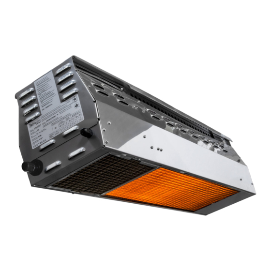
Schwank bistroSchwank Series Installation & Owner's Manual

Schwank bistroSchwank Series Installation & Owner's Manual

Advertisement

Quick Links

bistroSchwank Series
Models: 2135; 2150; 2152*
All models constructed with Marine Grade Stainless Steel Cabinet
* Two-stage Model 2152 / IO-152 is natural gas only
Approval: Patio Heater for Outdoor Commercial / Residential Application
And / or: Gas-Fired High Intensity Infrared Heater for Commercial /Industrial
INSTALLATION / OWNER'S MANUAL
WARNING
SAFETY ALERT:
This heater must be installed and serviced only by a trained gas service technician. Failure to
comply could result in personal injury, death, fire and/or property damage.
Do not store or use gasoline or other flammable vapors and liquids in the
vicinity of this or any other gas fired appliance.
Indoor Applications: The heater cannot be used indoors in a residence.
IF YOU SMELL GAS:
FIELD CONVERTIBILITY:
This appliance is field convertible to
LP gas [except 2152/IO-152: NG only].
Only use kit available from manufacturer.
Follow kit instructions and all local and
national codes.
Non-Residential Indoor Spaces
Improper installation, adjustment, alteration, service or
maintenance can cause property damage, injury or death.
Read the installation and operating and maintenance instruc-
tions thoroughly before installing or servicing this equipment.
Extinguish any open flame
Do not attempt to light this or any other appliance
Don't touch any electrical switch, or telephone
Immediately leave the area and call your gas supplier from a neighbor's phone
Follow any and all instruction from your gas supplier
If your gas supplier is not available, call the fire department
Series Models:
IO-135; IO-150; IO-152*
INSTALLER: PRESENT THIS MANUAL
TO THE END USER.
Keep this manual in a secure place.
Record for future reference:
Model #:
Serial #:
[located on heater rating label]
2100 / IO-100 Manual
IM110107
RD: AUG 2021
R.L. 11A

Advertisement

Table of Contents
loading

Summary of Contents for Schwank bistroSchwank Series

  • Page 1 Series Series Models: Models: 2135; 2150; 2152* IO-135; IO-150; IO-152* All models constructed with Marine Grade Stainless Steel Cabinet * Two-stage Model 2152 / IO-152 is natural gas only Approval: Patio Heater for Outdoor Commercial / Residential Application And / or: Gas-Fired High Intensity Infrared Heater for Commercial /Industrial Non-Residential Indoor Spaces INSTALLATION / OWNER’S MANUAL...
  • Page 2 This publication, or parts thereof, may not be reproduced in any form, without prior written consent from the manufacturer Unauthorized use or distribution of this publication is strictly prohibited. Schwank Group 2 Schwank Way Waynesboro, Georgia, USA 30830 5285 Bradco Boulevard...
  • Page 3: Table Of Contents

    Models: 2135; 2150; 2152 / IO-135; IO-150; IO-152 Patio Heater for Outdoor Commercial/Residential Application and Gas-Fired Luminous [High Intensity] Infrared Heater for Commercial / Industrial Non-Residential Indoor Spaces This heater model is approved to two different heater standards: • A “Patio Heater” for Outdoor Use in Residential and Commercial/Industrial Applications •...
  • Page 4: Important Information - Read First Important Warnings

    WARNING Improper installation, adjustment, alteration, service or maintenance can cause property damage, injury or death. Read and understand this installation and op- eration manual thoroughly prior to assembly, installation, operation or service to this appliance. This heater must be installed and serviced only by a trained gas service techni- cian.
  • Page 5: Heater Expansion

    WARNING Heater Expansion It is a normal condition that during heat-up and cool-down a radiant heater will expand and contract. Allowances for heater expansion must be made in the gas connection and heater suspension. Improp- er installation, alteration, or adjustment can result in property dam- age, injury or death.
  • Page 6: Outdoor' Definition

    INSTALLATION AS AN OUTDOOR PATIO HEATER What is “Outdoor”?: An appliance approved for “outdoor use” may be installed with shelter no more inclusive than: With walls on all sides, but with no overhead cover, [overhead permanently open] or • Within a partial enclosure which includes an overhead cover and no more than two side •...
  • Page 7: Outdoor

    Figure 1: OUTDOOR - MOUNTING CLEARANCES [Indoor Clearances Page 10] NOTE: MAXIMUM HEATER ANGLE IS 30° TO AVOID DAMAGE Note: Ensure mounting height in any location is sufficient to prevent patrons from coming in contact with heater, and clearance to combustible material is maintained. Table 1: OUTDOOR - MINIMUM MOUNTING &...
  • Page 8 If in doubt, please contact your Schwank / InfraSave distributor. Ensure mounting height in any location is sufficient to prevent patio patrons from coming in contact...
  • Page 9 WHEN INSTALLED INDOORS FOR COMFORT OR SPACE HEAT Also refer to “Outdoor” definition and requirements on page 16 • And refer to Indoor Ventilation Requirements Section 14 • WARNING Clearance to Combustibles Location of flammable or explosive objects, liquids or vapors close to the heater may cause fire or explosion and result in property damage, injury or death.
  • Page 10: Indoor

    Figure 3: INDOOR - MOUNTING CLEARANCES [Outdoor Clearances Page 7] NOTE: MAXIMUM HEATER ANGLE IS 30° TO AVOID DAMAGE Table 3: INDOOR - MINIMUM MOUNTING & CLEARANCES TO COMBUSTIBLES Ends Under HORIZONTAL UP TO MAXIMUM 30° ANGLE MODEL NO 2135 / IO-135 -N\L 14”...
  • Page 11: Dimensions & Configuration

    HEATER DIMENSIONS & CONFIGURATIONS Table 3: CAPACITIES & CONFIGURATIONS Voltage Current Total Weight Length MODEL* Btu/hr input amps lbs. [kg] Inches [mm] 2135 / IO-135 40 VA** 35,000 53 [24] 44” 2150 / IO 150 40 VA** 50,000 57 [26] 44”...
  • Page 12: Mounting Kit Options

    Figure 4: MOUNTING KIT OPTIONS NOTE: MOUNT HEATER AT MAXIMUM 30° ANGLE TO AVOID DAMAGE ITEM 1: UNIVERSAL MOUNTING ITEM 3: ARM WALL MOUNTING KIT JP-2300-MK JP-2100-CB-K Also see next page ITEM 4: POST MOUNTING KIT ITEM 2: WALL MOUNTING KIT JP-2300-PK JP-2100-MB Figure 5: MOUNTING OPTIONS...
  • Page 13 JP-2100-CB-K: Universal Mounting Kit for Patio Heaters Component Quantities and Material Specifications each Kit: 2 x Ceiling/Wall Bracket - 12 ga. [0.102”] 316 S/S 2 x 24” [610 MM] Channel Leg - 12 ga. [0.102”] 316 S/S 2 x Heater Attachment Bracket - 12 ga. [0.102”] 316 S/S 12 x ¼”...
  • Page 14 Figure 7: WALL MOUNT BRACKET JP-2100-MB 2100 / IO-100 Manual IM110107 RD: AUG 2021 R.L. 11A...
  • Page 15 Figure 8: HEATER INSTALLATION: JP-2100-MB WALL MOUNTING KIT NOTE: MOUNT AT MAXIMUM 30° ANGLE TO AVOID DAMAGING HEATER USE BRACKET AS TEMPLATE FOR HOLES/BOLTS TO THE STRUCTURE. FASTEN WALL BRACKET TO FASTEN TO STRUCTURAL MEMBER[S] STRUCTURE USING FIELD SUP- OR DEVISE STRUCTURAL SUPPORT TO PLIED FASTENING HARDWARE.
  • Page 16 JP-2300-MK ARM WALL MOUNTING KIT NOTE: MOUNT HEATER AT MAXIMUM 30° ANGLE Using pairs of holes in the heater bracket allows heater orientation: Horizontal • Angled at 30° • [MAXIMUM angle mount] Assemble Mounting Bracket to Mounting Arm using bolts and nuts supplied: Align the anchor holes in •...
  • Page 17 JP-2300-PK POLE MOUNTING KIT USE CARE NOT TO DAMAGE OR SCRATCH HEATER DURING INSTALLATION FASTEN THE TWO POLE CLAMPS TO STRUCTURE USING FIELD SUPPLIED FASTENING HARDWARE.ENSURE SUFFICIENT STRENGTH AND INTEGRITY TO CARRYY WEIGHT OF HEATER AND WIND/SNOW LOADS FASTEN HEATER BRACKET TO STUDS ON TOP OF HEATER INSTALL THE TWO POLE CLAMPS ON TO WALL BRACKET USING BOLTS...
  • Page 18: Application

    This heater is certified for use on outdoor patio’s in accordance with ANSI Z83.26 / CSA 2.37 . Schwank warrants that the heater will operate as designed in mild wind conditions up to 10 MPH. Note this unit is not designed to operate in adverse weather conditions including higher wind speeds exceeding the certification requirement of 10 MPH.
  • Page 19: Aircraft Hangars

    INSTALLATION IN COMMERCIAL AIRCRAFT HANGARS Luminous [high intensity] radiant tube heaters are suitable for use in aircraft hangars when in- stalled in accordance with the latest edition of the Standard for Aircraft Hangars, ANSI/NFPA No 409 in the USA, or the Canadian Natural Gas and Propane Installation Code, B149.1. A.
  • Page 20: Installation Requirements

    Use only non-combustible mounting hardware and maintain at least the minimum clear- ances to combustibles. Also see Pages 11 to 17 and Figures 4 & 5 on Page 12 that illustrate typical suspension hardware that may be used. Mounting kits can be provided by Schwank as an optional component.
  • Page 21: Gas Supply Piping

    For outdoor installation the connector must be in compliance with ANSI Z21.75 / CSA 6.27. A 3/8” x 24” black finish flexible gas connector [JL-0771-OD - ap- proved Indoor/Outdoor] is available as an option from Schwank / InfraSave. A drip-pocket must be provided at the inlet connection •...
  • Page 22: Layout, Comfort & Control

    PROPER WIRING POLARITY MUST BE MAINTAINED, particularly when grouping the heat- ers in a zone. Total wiring distances of up to 200' must use minimum 16 gauge electrical wire, and wiring distances of over 200' must use minimum 14 gauge electrical wire. The heater must be electrically grounded in accordance with local and national electrical codes.
  • Page 23: Installation Procedures

    Heater/Zone Control Options : Locate controls in a secure staff area. Single-Stage Models: 2135 / 2150; IO-135 / IO-150 On/Off power switch • patioControl Panel: Manual control by staff; JM-0204-NT up to 4 heater zones; • JM-0208-NT up to 8 heater zones; JM-0212-NT up to 12 heater zones Wireless remote control: refer to section 15 page 23 •...
  • Page 24: Lighting Instructions

    11. LIGHTING INSTRUCTIONS 1. Ensure the correct voltage is supplied, gas supply lines have been properly purged, and gas valve is switched to the ON position. 2. Turn on power to heater [high or low rate for 2-stage heater], set thermostat [if applicable] to above ambient temperature, the heater will light.
  • Page 25: Servicing Guide

    13. SERVICING GUIDE [Also refer to Troubleshooting Guide on page 38] Servicing of heater is essential for continued efficient operation. Servicing should be carried out annually by a qualified gas service technician as follows: Clean the ceramic tiles with compressed air. Avoid directing air stream at gasket material •...
  • Page 26: Ventilation For Indoor App's

    The exhauster should be as centrally located as practicable in the zone of heaters. Schwank recommends a maximum 6:1 ratio of the horizontal distance be- tween the exhauster and the furthest heater in a zone, to the height the heaters are mounted above the floor .
  • Page 27: Remote Control Options

    fan should be located no more than 120 ft from the furthest heater in the zone. Sufficient air supply must be provided. Exhauster Capacity: USA: Natural or mechanical means shall be provided to supply and exhaust at least /min/1000Btuh [0.38m /min/kW] Natural Gas input of installed heaters [4.5ft min/1000Btuh [0..43m /min/kW] Propane input].
  • Page 28: Remote Control Quick Setup

    [Single-Stage Models ONLY] 2100 / IO-100 Manual IM110107 RD: AUG 2021 R.L. 11A...
  • Page 29 Single-Stage Models only 2100 / IO-100 Manual IM110107 RD: AUG 2021 R.L. 11A...
  • Page 30 Single-Stage Models only 2100 / IO-100 Manual IM110107 RD: AUG 2021 R.L. 11A...
  • Page 31 Single-Stage Models only 2100 / IO-100 Manual IM110107 RD: AUG 2021 R.L. 11A...
  • Page 32 Single-Stage Models only 2100 / IO-100 Manual IM110107 RD: AUG 2021 R.L. 11A...
  • Page 33: Sequence Of Operation-Fenwal 35-60 Dsi

    16. SEQUENCE OF OPERATION FOR FENWAL 35-60 DSI CONTROL Start up - Heat Mode: On a call for heat the Fenwal 35-60 control will reset, perform a self check routine, flash the diagnostic LED for up to four seconds. The gas valve and spark are energized commencing the trial for ignition period.
  • Page 34: Spark Ignition Circuit

    Cautions: 1. The ceramic insulator of the igniter assembly should not be in or close to the flame. 2. The electrode assembly should not be disassembled and care must be used in making mi- nor gap adjustment. The spark electrode should have a gap spacing of 1/8”- 3/16” [3.12±...
  • Page 35: 18-A Wiring Diagram - Single-Stage

    18-A. WIRING DIAGRAM: 2100 / IO-100 Single-Stage: Fenwal 35-60 DSI If installing remote control kit JP-1235-RK refer to wiring diagram in the remote control manual Fenwal Control Terminal Designation Error Mode LED Indication Internal Control Failure Steady on Thermostat / 24V Supply Input System Ground Flame with No Call for 2 flashes...
  • Page 36: 18-B Wiring Diagram - Two-Stage

    18-B. WIRING DIAGRAM: 2152 / IO-152 Two-Stage: Fenwal 35-60 DSI - see control switch wiring next page 2100 / IO-100 Manual IM110107 RD: AUG 2021 R.L. 11A...
  • Page 37: 18-C Wiring - 2-Stage Switch Control

    18-C. WIRING DIAGRAM: Two-Stage Switch Control Further information on 2-Stage Control Switches - Page 41 2100 / IO-100 Manual IM110107 RD: AUG 2021 R.L. 11A...
  • Page 38: Troubleshooting Guide

    19. TROUBLESHOOTING GUIDE *CHECK 120 V AT PRIMARY TRANSFORMER TURN HEATER ON *CHECK VOLTAGE OUT AT SECONDARY. *IF THERE IS NOT 24V TO SECONDARY...REPLACE THE TRANSFORMER *CHECK 24V WIRING FROM TRANSFORMER 24 VOLTS ±10% TO DSI CONTROL TO IGNITION CONTROL / AND CHECK IF CORRECT GAUGE OF WIRE FOR DISTANCE.
  • Page 39 MAIN BURNER LIGHTS CHECK FOR CORRECT MANIFOLD GAS PRESSURE *CHECK FOR OBSTRUCTION IN GAS SUPPLY OR OR- IFICE [INSECTS, SPIDERS COCOONS ETC.] CHECK FLAME SIGNAL WITH METER FOR 0.7µA. IF READING IS LOW CHECK GAS PRESSURE, IF OK SPARK STOPS WHEN BURNER LIT.
  • Page 40: Commissioning Report

    20. COMMISSIONING REPORT This heater has been factory fired and tested prior to shipment. However, it is not a ’Plug-in’ appliance. Commissioning and field adjustment to correct settings is required. COMPLETE THIS COMMISSIONING REPORT AND FILE THIS MANUAL AT SITE FOR FUTURE REFERENCE INSTRUCT THE END USER THAT THIS MANUAL MUST BE KEPT SECURE A QUALIFIED SERVICE TECHNICIAN CALLING FOR TECHNICAL SUPPORT MUST PROVIDE THE INFORMATION FROM THE...
  • Page 41 HEATER COMMISSIONING TECHNICAL REPORT TYPE OF GAS HEATER IS EXPOSED TO CHENICAL OR CORROSIVE ATMOSPHERE OPEN COMBUSTION IS COMPATIBLE WITH THE INSTALLED LOCATION MINIMUM CLEARANCES CONFORM TO REQUIREMENTS OF THIS MANUAL WHAT IS THE ALTITUDE OF THIS PROJECT LOCATION ABOVE SEA LEVEL FEET IS ALTITUDE ADJUSTMENT REQUIRED? [See Section 21 next page] ...
  • Page 42: High Altitude Deration

    21. HIGH ALTITUDE INSTALLATION / DERATION This heater not to be installed at altitude above 6,800 feet. USA: The factory installed orifice for this appliance is approved for altitudes zero to 2000 feet above sea level. When installed above 2000 feet, refer to information below. Canada: The factory installed orifice for this appliance is approved for altitudes zero to 4500 feet above sea level.
  • Page 43: Accessories: Control & Mounting

    22. CONTROL ACCESSORIES Two-Stage Illuminated Switch Gang Assemblies [24Vac capacity] • One or a combination of these switch gangs is required to control 2-stage heaters • Illuminated switches marked one indicate low stage or two indicate high stage oper- ation at a glance •...
  • Page 44 Heater Mounting Hardware Options - Refer to pages 11 to 17 for details NOTE: MOUNT HEATER AT MAXIMUM 30° ANGLE TO AVOID DAMAGE JP-2100-CB-K UNIVERSAL MOUNTING KIT Mounts directly to top of the heater.  Allows rotation of the channel arm up to ...
  • Page 45: Replacement Parts List

    23. Replacement Parts List Note: HI VOLTAGE WIRE - SPARK 2100 - JX-0228-XX LEAD WIRE 15" - SENSOR FLAME - JA-0569-LW 2135 / IO-135 2150, 2152 / IO-150, -152 REPLACEMENT PARTS LIST ORDER QUANTITY PART NAME PART # PART # CONTROL SIDE DIVIDER 2100 JP-2100-IG-A JP-2100-IG-A...
  • Page 46 2150, 2152 / 2135 / IO-135 REPLACEMENT PARTS LIST ORDER IO-150, IO-152 QUANTITY PART NAME PART # PART # INTERIOR REFLECTOR/HEAT SHIELD 2100 Each JP-2100-RS JP-2100-RS [ONE EACH SIDE] LIQUID TIGHT FITTING PGB9 JP-2036-XX JP-2036-XX HORIZONTAL SPACER PLATE 2100 JP-2135-HP INTERIOR BURNER END PLATE 2100 JP-2100-IE JP-2100-IE...
  • Page 47 2150, 2152 / STANDARD BLACK FINISH - ENCLOSURE PARTS 2135 / IO-135 ORDER IO-150, IO-152 QUANTITY PART NAME PART # PART # HANGING SUPPORT BRACKET 2100 [316 SS] JP-2100-HS-SP JP-2100-HS-SP PAINTED LEFT EXTERIOR PANEL 2100 [316 SS] PAINT- JP-2100-RP-LSP JP-2100-RP-LSP BURNER END PLATE 2100 [316 SS] PAINTED JP-2100-EP-SP JP-2100-EP-SP...
  • Page 48: Limited Warranty

    This warranty gives you specific legal rights. You may also have other rights which vary by jurisdiction. SCHWANK & INFRASAVE 2 SCHWANK WAY, WAYNESBORO, GEORGIA. 30830 5285 BRADCO BLVD. MISSISSAUGA, ON,...

This manual is also suitable for:

Infrasave series213521502152Io-135Io-150

Table of Contents