Table of Contents
Advertisement
Quick Links
SET - SETU Series
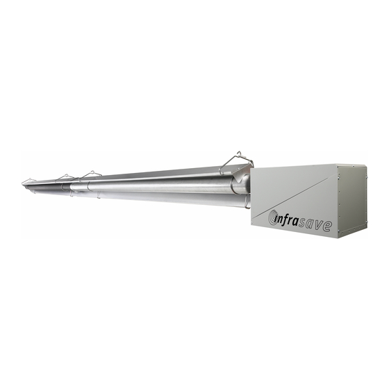
TWO-STAGE LOW INTENSITY TUBE TYPE INFRARED HEATERS
INSTALLATION / OWNER'S MANUAL
SAFETY ALERT:
This heater must be installed and serviced only by a trained gas service techni-
cian. Failure to comply could result in personal injury, death, fire and/or property
damage.
Do not store or use gasoline or other flammable vapours and liquids in the
vicinity of this or any other gas fired appliance.
IF YOU SMELL GAS:
◼
◼
◼
◼
◼
◼
FIELD CONVERTIBILITY:
This appliance is field con-
vertible to Propane.
For Indoor Use
Improper installation, adjustment, alteration, service or
WARNING
maintenance can cause property damage, injury or death.
Read the installation and operating and maintenance instruc-
tions thoroughly before installing or servicing this equipment.
Extinguish any open flame
Do not attempt to light this or any other appliance
Don't touch any electrical switch, or telephone
Immediately call your gas supplier from a neighbor's phone
Follow any and all instruction from your gas supplier
If your gas supplier is not available, call the fire department
Keep this manual in a secure place .
Record for future reference:
Model #:
Serial #:
ITT - ITTU Series
&
(located on heater rating label)
SET(U) / ITT(U) Manual
IM091221
RD: APR 2019
RL: 13C
Advertisement
Table of Contents
Troubleshooting

Related Manuals for Schwank infrasave SET Series


Summary of Contents for Schwank infrasave SET Series
- Page 1 SET - SETU Series ITT - ITTU Series & TWO-STAGE LOW INTENSITY TUBE TYPE INFRARED HEATERS For Indoor Use INSTALLATION / OWNER’S MANUAL Improper installation, adjustment, alteration, service or WARNING maintenance can cause property damage, injury or death. Read the installation and operating and maintenance instruc- tions thoroughly before installing or servicing this equipment.
- Page 2 The Manufacturer. Unauthorized use or distribution of this publication is strictly prohibited. Schwank Group Schwank and InfraSave brands 5285 Bradco Boulevard Mississauga, Ontario,L4W 2A6 PO Box 988, 2 Schwank Way Waynesboro, Georgia 30830 Customer & Technical Services Phone: 877-446-3727 Fax: 866-361-0523 e-mail: csr@schwankgroup.com www.schwankgroup.com...
-
Page 3: Table Of Contents
SET / SETU and ITT / ITTU SERIES GAS FIRED INFRARED LOW INTENSITY TUBE TYPE TABLE OF CONTENTS TOPIC ..PAGE TOPIC ……...PAGE 14. ELECTRICAL AND THERMOSTAT ....32 IMPORTANT INFORMATION - READ FIRST 15. HIGH ALTITUDE INSTALLATION ....32 APPLICATION .......... -
Page 4: Application
WARNING Improper installation, adjustment, alteration, service or mainte- nance can cause property damage, injury or death. Read and understand this installation and operation manual thoroughly prior to assembly, installation, operation or service to this appliance. This heater must be installed and serviced only by a trained gas service techni- cian. -
Page 5: Heater Expansion
WARNING Heater Expansion It is a normal condition that during heat-up and cool-down a tube heater will expand and contract. Allowances for heater expansion must be made in the gas connection, venting and combustion air ducting. Improper installation, alteration, or adjustment can result in property damage, injury or death. -
Page 6: Tube 'Glow
WARNING Tube “GLOW” It is a normal condition that the combustion tube (1st tube) can appear to “glow red”. For inputs up to 150,000 Btuh, the top surface of the tube can appear red where heat is trapped between the reflector and the tube. The stainless steel tube used for inputs 175,000 and greater can ap- pear to entirely glow red. -
Page 7: Clearances Figure & Table
FIGURE 1 MINIMUM CLEARANCES TO COMBUSTIBLES* - refer to Table 1 for values NOTE: A ‘PEEL & STICK’ SIGN IS SUPPLIED: USE AN INDELIBLE MARKER TO ENTER VALUES ‘H’, ‘S’, ‘F’, & ‘B’ ON . POST THE SIGN ADJACENT TO THE HEATER THERMOSTAT OR IN A See next page for details. -
Page 8: Stacking Height Sign
tolerance which may degrade at lower temperatures are protected to prevent degrada- tion. Examples of low heat tolerance materials include vinyl siding, fabrics, some plas- tics, filmy materials, etc. VENT END CLEARANCE: Clearances from the vent pipe are determined by local or national installation codes, but must not be less than 6 inches (15 cm). -
Page 9: Labor Requirements
1. LABOR REQUIRMENTS Two persons are required to safely install this equipment. Wear gloves and other required safe- ty protection. INSTALLATION IN COMMERCIAL AIRCRAFT HANGARS Low intensity radiant tube heaters are suitable for use in aircraft hangars when installed in ac- cordance with the latest edition of the Standard for Aircraft Hangars, ANSI/NFPA No 409 in the USA, or the Canadian Natural Gas and Propane Installation Code, B149.1. -
Page 10: Pre-Installation Survey
WARNING Improper installation, adjustment, alteration, service or maintenance can cause property damage, injury or death. Read and understand this installation and operation manual thoroughly prior to assembly, installation, operation or service to this appliance. This heater must be installed and serviced only by a trained gas service technician. Do not store or use gasoline or other flammable vapours and liquids in the vicinity of this or any other gas fired appliance. -
Page 11: Mounting Clearances
6. MOUNTING CLEARANCES This heater must be mounted with at least the minimum clearances between the heater and combustibles as shown in FIG.1, TABLE 1. It is the installer’s responsibility to ensure that building materials with a low heat tolerance which may degrade at lower temperatures are pro- tected to prevent degradation. -
Page 12: Heater Placement Guidelines
TABLE 2: GUIDELINES FOR HEATER PLACEMENT DISTANCE – OUTSIDE WALL MAXIMUM TO HEATER LONG AXIS MODEL GUIDELINE DISTANCE (PARALLEL TO WALL) IN “FEET” MOUNTING BETWEEN “Straight” or HEIGHT HEATERS HORIZONTAL “U-Tube” ft (m) ANGLE ft (m) ft (m) 18 – 25 (6 - 8) 50 (15) 17 –... -
Page 13: Elbow Kit Dimensions
IMPORTANT: Elbow Location / Input: A minimum run of straight radiant tube must be connected to the burner before any elbow as follows: Inputs 200 (60 kW) and 175 Mbh (50 kW) = 25 ft (7.6 m); Input 155 Mbh (45 kW) = 20 ft (6 m); Inputs 130 Mbh (38 kW) and 110 Mbh (32 Kw) = 15 ft (4.6 m);... -
Page 14: Suspending The System
8. SUSPENDING THE SYSTEM - GENERAL Inadequate or improper suspension of the tube heater can result in collapse of the system, property damage, and personal injury or death. It is the installer’s responsibility to ensure that the hardware and structural sup- ports from which the heater is suspended are sound and of adequate strength to support the weight and expansion forces of the heater. -
Page 15: Straight Tube System
9 INSTALLATION OF HANGERS, TUBES AND BURNER TURBULATOR NOTES: See Section 26, pages 45-46 for details on turbulator sizes and location in system Prior to Installation: 80 / 60 x 30 ft: Remove and discard 60” turbulator from the second tube ... - Page 16 FIGURE 8A: INSTALL FLAME RECTIFIER IN TUBE , THEN INSTALL IGNITER All input rates: EXCEPT 80/60 does not require a flame rectifier. Flame Rectifier is shipped inside the Burner box. Igniter is shipped taped inside the Burner box. 1 Remove & retain sight glass 3 Feet of the flame rectifier seat 4 Reinstall sight glass against the tube flange and...
-
Page 17: U' Tube System
SETU / ITTU ‘U’-TUBE SYSTEM ~ BURNER AND TUBE INSTALLATION TURBULATOR NOTES: Refer to Section 26, pages 45-46 for details on turbulator sizes and location in system Prior to Installation: 200 / 140 x 30 ft-U : Remove and discard 40” turbulator from the upstream end of last ... - Page 18 FIGURE 11 ‘U’-TUBE TYPICAL HANGER & SUPPORT SPACING SUSPEND FIRST TUBES BY TWO (2) HANGERS, THEN SUBSEQUENT SECTIONS BY ONE HANGER LOCATE HANGERTS BETWEEN 6” to 18” FROM EACH TUBE COUPLER. INSTALL FIRST AND SECOND TUBES (FROM BURNER END) WITH WELDED SEAM FACING DOWNWARD. 1 - END CAP 4B - JS-0532-VC 4”...
-
Page 19: Special Coupling - 175 & 200 Mbh
9.3 SPECIAL COUPLING: 175,000 & 200,000 Btuh NOTE: The joint of 1ST & 2ND tubes of 175,000 & 200,000 heaters experience strong forces of expansion. Follow instructions below for special coupling of the tubes. SPECIAL COUPLER INSTALLATION Note the 2 holes opposite each other at the swaged end of the first tube (flanged) Install the first tube with 2 holes (swaged end) at the 3 and 9 o’clock position, with the welded seam located in the lower half of tube, facing downward Slide the loosened tube coupler on to the first tube, past the swage... -
Page 20: Reflector Installation
10. REFLECTOR INSTALLATION NOTE: Ensure that you are installing a single reflector - reflectors can ‘stick together’ in packaging - take care to separate them. SET / ITT - STRAIGHT TUBE : After burner and tubes have been installed, slide the re- flectors one at a time into the wire hangers. - Page 21 FIGURE 15 REFLECTOR EXTENSIONS (OPTIONAL - IF REQUIRED ) Reflector Extension Kit JS-0509-KT Includes: • Qty 1 x 10 ft long x 10 inch deep reflector extension • Qty 3 x “S” Hooks Reflector extensions may be installed one or both sides 1.
-
Page 22: Flue Venting
11. FLUE VENTING - RADIANT TUBE HEATER Effective January 1, 2019: Changes to the ANSI/CSA standard that gov- IMPORTANT erns Radiant Tube Heaters specify the following appliance CATEGORIES and VENTING: Vertical Vent Through Roof (Category I): For vertical vent, this tube heater series operates ◼... - Page 23 appliance Category, and specifications below. ◼ All venting must meet requirements of Local Codes or, in the absence of local codes, with the ◼ National Fuel Gas Code, ANSI Z223.1/NFPA 54; or the Natural Gas and Propane Installation Code CSA B149.1. A vent connector shall comply with local codes and be firmly attached to the flue collar by 3 x ◼...
- Page 24 TABLE 3 COMBINED SYSTEM LENGTH: TUBE + AIR DUCT + VENT Installations up to 4500 ft - Higher altitudes refer to Section 27 Max. Air Duct Do Not Exceed Example Max. Vent Max. Combined Length* Length* SET / ITT System Length* (by Duct Diameter) 155/110 Model: Individual: 4”...
- Page 25 Vertical vent through the roof (Category I): It is the sole responsibility of the installer to adhere to all current local codes and/or ANSI Z223.1 / CSA.B149.1 latest editions for all venting requirements, and practices. Also adhere to instructions below, and the instructions of the vent manufacturer. Use vent materials certified for Category I. All models of this series heater are certified Category I for vertical venting.
- Page 26 Horizontal vent through the sidewall (Category III): All vent must be installed in accordance with local codes or, in the absence of local codes, with the National Fuel Gas Code in the USA, ANSI Z223.1/NFPA 54; or the Natural Gas and Propane Instal- lation Code CSA B149.1 in Canada.
- Page 27 USA specific horizontal vent requirements: The vent terminal of an appliance with an input up to 50,000 Btu/hr (14.7kW) shall be in- ◼ stalled with a 9 inch [230mm] vent termination clearance from any air opening into a building, and an appliance with an input over 50,000 Btu/hr (14.7kW) shall have at least a 12 inch [305 mm] vent termination clearance.
-
Page 28: Combustion Air Duct
12. COMBUSTION AIR DUCTING Do not install filters on the combustion air intake. Ensure adequate clearance around the air intake to allow sufficient combustion air supply to the heater. An opening is located on the top surface of the burner housing for combustion air . Ensure ad- equate clearance around this opening to allow sufficient combustion air supply to the heater. -
Page 29: Gas Supply
GAS SUPPLY - HEATER EXPANSION - FLEXIBLE GAS CONNECTION The gas supply must be installed to the heater using: USA: an approved Stainless Steel Flexible Gas Connector certified for use on an infrared • radiant tube heater (ANSI Z21.24 CSA 6.10); CANADA: an approved Type 1 Hose Gas Connector (CAN/CGA 8.1). -
Page 30: Heater Expansion
NOTE: Access to the manifold pressure test port is on the top of the valve. A 3/16" Allen Wrench is necessary to check this. When checking or setting the manifold pressure, a water manometer should be used. Gauges which measure in ounces per square inch or pounds per square inch are not accurate enough to properly measure or set the pressure. -
Page 31: Flexible Gas Connection
FIGURE 20 ORIENTATION OF FLEXIBLE GAS CONNECTOR The flexible gas connector MUST be installed in the orientation shown below as required by national installation codes and by the certification standard of this heater. This orientation protects the flexible gas connector from damage due to movement during heater expansion. -
Page 32: Electrical And Thermostat
145VA. The heater includes a 24V/120V relay switch and is to be controlled by a Honeywell FocusPRO 5000 Series TH5220D1037 (or equivalent) 24V Digital Thermostat - Schwank/ InfraSave P/N JS-0569-DT. Maximum power flow for internal 24V burner components is 21VA. -
Page 33: Wiring Diagram Fenwal Dsi
18. WIRING DIAGRAM FENWAL DSI 24 VOLT TWO STAGE GAS VALVE – USING 24V TWO STAGE THERMOSTAT (FOR MULTIPLE HEATERS PER THERMOSTAT SEE NEXT PAGE) SET(U) / ITT(U) Manual IM091221 RD: APR 2019 RL: 13C... -
Page 34: Wiring Diagram Multiple Heaters Per 2-Stage Thermostat
19. WIRING DIAGRAM - MULTIPLE 2-STAGE HEATERS PER 2-STAGE THERMOSTAT (FOR SINGLE HEATER PER THERMOSTAT SEE PREVIOUS PAGE) NOTE: Total Relays Required Thermostat: 2 Relays Each Heater: 2 Relays Example: Quantity 4 two-stage heaters requires: 2 + (4 x 2) = 10 Relays (previous page) Maximum Power Flow = 21VA SET(U) / ITT(U) Manual... -
Page 35: Fenwal Dsi: Sequence Of Operation
20. FENWAL DSI: SEQUENCE OF OPERATION / FLAME RECOVERY / SAFETY LOCKOUT Power Up / Stand By Upon applying 24 volts power to 24VAC, the control will reset, perform a self check routine, initi- ate full time flame sensing, flash the diagnostic LED for up to four seconds, and enter the ther- mostat scan state. - Page 36 Flame Fault If at any time the main valve fails to close completely and maintains a flame, the full time flame sense circuit will detect it and energize the combustion blower. Should the main valve later close completely removing the flame signal, the combustion blower will power off following the optional post purge period.
-
Page 37: Spark Igniter Adjustment
SPARK IGNITER ADJUSTMENT Use the following diagram to check the Igniter gap. If the gap is incorrect all adjustments should be made to the GROUND PRONG/PIN ONLY! DO NOT BEND THE IGNITER PRONG!!!! USE THE BLACK BARS BELOW AS A GUIDE FOR AD- JUSTMENT. -
Page 38: Troubleshooting Guide: Fenwal Dsi
21. TROUBLESHOOTING GUIDE - FENWAL DSI (also see Heater Troubleshooting next page) SYMPTOM RECOMMENDED ACTION(S) A. Miswired - check electrical supply (120Vac ± 5%) B. Transformer bad (24Vac ± 10%) 1. Dead C. Fuse/Circuit breaker bad D. Bad control (check LED for steady on) A. -
Page 39: Troubleshooting Guide: Heater
22. TROUBLESHOOTING GUIDE - HEATER OPERATION WARNING Improper adjustment, alteration, service or maintenance can cause property damage, injury or death. This heater must be SEQUENCE OF EVENTS (also see DSI Troubleshooting previous page) APPLY 120 VOLTS • REMEDY 120 VOLTS SUPPLY FAULT SET THERMOSTAT TO CALL FOR HEAT •... - Page 40 MAIN BURNER LIGHTS • CHECK FOR STRONG SPARK AT IGNITER..• (SEE PREVIOUS PAGE). • CHECK FOR 24 VAC ACROSS GAS VALVE. • CHECK OUTPUT VOLTAGE FROM CONTROL TER- MINALS TO GAS VALVE..IF NO VOLTAGE RE- PLACE CONTROL. • CHECK ELECTRICAL WIRING, AND VOLTAGE BE- TWEEN IGNITION CONTROL AND GAS VALVE.
-
Page 41: Start- Up / Commissioning Sheet
23. START-UP / COMMISSIONING SHEET THIS EQUIPMENT HAS BEEN FACTORY FIRED AND TESTED PRIOR TO SHIPMENT. HOWEVER, THIS APPLIANCE IS NOT “PLUG & PLAY”. IT RE- QUIRES COMMISSIONING AND FIELD ADJUSTMENT / SPECIFICATIONS CONFIRMATION TO ENSURE SAFE AND EFFICIENT OPERATION. COMMISSIONING REPORT AS PER I&O MANUAL AND LOCAL/NATIONAL CODES CONTRACTOR:... - Page 42 QUALIFIED INSTALLER TO COMPLETE THIS TUBE HEATER COMMISSIONING REPORT 1-877-446-3727 REFER TO THIS COMPLETED REPORT WHEN CALLING TECHNICAL SERVICES: TYPE OF GAS HAS A MANUFACTURER’S GAS CONVERSION KIT BEEN INSTALLED DOES BUILDING HAVE A ‘NEGATIVE AIR’ CONDITION IS HEATER EXPOSED TO CHEMICAL OR CORROSIVE ATMOSPHERE IS ‘OUTSIDE COMBUSTION AIR’...
- Page 43 24. MODEL BTUH INPUT RATINGS AND CORRESPONDING DIMENSIONS NOMINAL OVERALL APPROX HIGH-FIRE LOW-FIRE SET / ITT SET / ITT TUBE HEATER INPUT INPUT MODEL MODEL LENGTH LENGTH * WEIGHT ** (BTUH) (BTUH (FT) (FT) (LBS) 200/140 195,000 140,000 200/140 50’ 4” 175/125 162,000 115,000...
- Page 44 FIGURE 21 BURNER DIMENSIONS FIGURE 22 HANGER SPACING / LENGTH - AIR INTAKE TO VENT END • POSITION BURNER END HANGER 4 INCHES (10 CM) FROM BURNER • LOCATE SYSTEM HANGERS NO LESS THAN 6 INCHES (15 CM) AND NO MORE THAN 24 INCH- ES (61 CM) FROM TUBE COUPLING * ANGLE BURNER SUPPORT CHAIN BACK OVER BURNER - ALLOWS TUBE SYSTEM EXPANSION Tube...
-
Page 45: Installation Dimensions 25. Burner / Tube Kit Assembly Chart Straight Tube System
25A. BURNER & TUBE KIT ASSEMBLY CHART MODELS SET / ITT MODELS SET & ITT are approved for indoor commercial / industrial non-residential applica- tions. For outdoor, wet and harsh environment applications refer to models SPW-JZ / IWP (powder coated burner box) and/or STW-JZ / IW (stainless steel burner box). BEFORE INSTALLING: ENSURE you have the CORRECT TUBE KIT(s) for the BURNER INPUT 'SET / ITT' TUBE KIT PART # &... -
Page 46: U' Tube System
25B. BURNER & TUBE KIT ASSEMBLY CHART MODELS SETU / ITTU MODELS SETU & ITTU are approved for indoor commercial / industrial non-residential appli- cations. For outdoor, wet and harsh environment applications refer to models SPW-JZ / IWP (powder coated burner box) and/or STW-JZ / IW (stainless steel burner box). BEFORE INSTALLING: ENSURE you have the CORRECT TUBE KIT(s) for the BURNER INPUT SETU / ITTU TUBE KIT PART # &... -
Page 47: Turbulators
TURBULATORS: NOTE: Improper location of a turbulator can cause malfunction of the heater, property damage, and will void the heater warranty. Tube Heaters are supplied with all required turbulator(s) factory installed into the tube(s) and are clearly labeled for identification. Refer to tables below, and illustration next page for turbulator lengths and locations in system. -
Page 48: Turbulator Illustration
TURBULATOR LENGTH & LOCATION IN SYSTEM: 130/90x 30’ NG ONLY 130/90x 15’U NG ONLY SET(U) / ITT(U) Manual IM091221 RD: APR 2019 RL: 13C... -
Page 49: High Altitude & Orifice Chart
4500 feet above sea level. When installed above 4500 feet, refer to the Local Provincial Authority having jurisdiction. Also refer to ‘Total System Length Restrictions’ for altitudes above 4500 ft on next page. SCHWANK/INFRASAVE RECOMMENDED ORIFICE CHART - ALTITUDE CONVERSION FOR USE AT ALTITUDES GREATER THAN (FEET) Gas Orifice Drill Size / Part#... - Page 50 27.HIGH ALTITUDE INSTALLATION - Total System Length Restrictions NOTE: Installations above 4,500 ft: Restrict the Total Combined System Length as indi- cated in the TOTAL SYSTEM LENGTH RESTRICTIONS Table below. MINIMUM VENT LENGTH: (Vented or Unvented [indirect mechanical ventilation]) Minimum vent length of 3 ft (91 cm) is required (NOTE: 200,000 : Minimum 8 ft (244 •...
-
Page 51: Optional Accessories
28. OPTIONAL ACCESSORIES JL-0800-XX #2 Lion Chain (115 lb work load) - 200 ft roll ‘S’ Hooks - 1 7/8” - package of 25 JL-0798-SH Flue Vent Terminal 4” wall horizontal JA-0528-XX 6” wall horizontal JA-0529-XX Torctite Coupler Sufficient quantity supplied with heater JA-0516-SW Use for connection of vent tee, or... - Page 52 Fresh Air Intake Adapter JS-0532-SE Fresh Air Intake Cap—Wall JS-0532-VC Fresh Air Intake Cap—Roof 4” roof cap JA-0530-XX JA-0531-XX 6” roof cap 2-Stage Low Voltage Digital Thermostat (24 Volts - °F or °C selectable) JS-0569-DT Not for use in corrosive or wet environments Required For MULTIPLE HEATERS per Thermostat: 24 RELAY...
-
Page 53: Burner Parts List
JS-0508-SM 90 degree Aluminized Steel Elbow (Kit includes: aluminized steel elbow, coupler, and two reflector end caps) For 180° elbow use two x JS-0508-SM, or use Model SETU / ITTU that includes 180° Turn Box Side Reflector Extension Kit- l0” deep, l0 ft long Each JS-0509-KT Includes 3 ‘S’... - Page 54 29. REPLACEMENT PARTS SET / ITT Series Burner Burner Parts: Models SET, SET-F, SET-X; ITT, ITT-F, ITT-X Note the Model # & Dash # on the rating plate for correct part(s) Model Dash # / Nominal High Input / Gas Type PART DESCRIPTION PART All Models...
- Page 55 … continued from previous page Burner Parts: Models SET, SET-F, SET-X; ITT, ITT-F, ITT-X Note the Model # on the rating plate for correct part(s) Model Dash # / Nominal High Input / Gas Type PART # PART DESCRIPTION 5 SET/ITT & -F Model: 130 Propane Gas orifice low intensity HTR 29 DMS JS-0729-DM SET/ITT &...
- Page 56 … continued from previous page Burner Parts: Models SET, SET-F, SET-X; ITT, ITT-F, ITT-X Note the Model # on the rating plate for correct part(s) PART # Model Dash # / Nominal High Input / Gas Type PART DESCRIPTION 18 SET/ITT & -F Model: 80 & 110 NG & Pro- Air proving switch 0.65"...
-
Page 57: Tube System Parts List
SET / ITT & SETU / ITTU TUBE SYSTEM PARTS Tube System Parts: Models SET & SETU, ITT & ITTU & -F, -X Models Note the Model # & Dash # on the Burner rating plate for correct part Model / Nominal High Input PART DESCRIPTION PART # -X Models only: 110, 130 &... - Page 58 Warranty is only applicable to Schwank components, other parts are limited to their own Manufacturers warranty period of one year (1 year).
Need help?
Do you have a question about the infrasave SET Series and is the answer not in the manual?
Questions and answers