Table of Contents
Advertisement
Quick Links
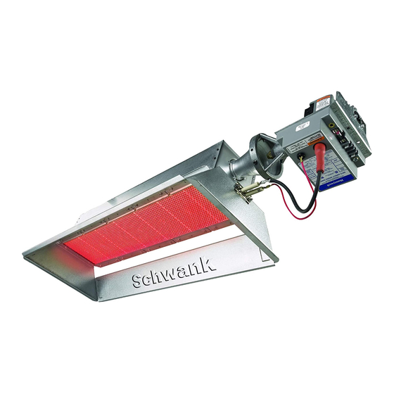
ecoSchwank-X
36, 52
Gas-Fired Luminous (High Intensity) Infrared Heaters
INSTALLATION / OWNER'S MANUAL
SAFETY ALERT:
This heater must be installed and serviced only by a trained gas service techni-
cian. Failure to comply could result in personal injury, death, fire and/or property
damage.
Do not store or use gasoline or other flammable vapours and liquids in the
vicinity of this or any other gas fired appliance.
IF YOU SMELL GAS:
FIELD CONVERTIBILITY:
This appliance is field con-
vertible to LP gas. Use kit
available from manufacturer.
See page 14. Follow all lo-
cal and national codes.
Improper installation, adjustment, alteration, service or
WARNING
maintenance can cause property damage, injury or death.
Read the installation and operating and maintenance instruc-
tions thoroughly before installing or servicing this equipment.
Not approved for use in any residential application.
Extinguish any open flame
Do not attempt to light this or any other appliance
Don't touch any electrical switch, or telephone
Immediately leave the area and call your gas supplier from a neighbor's
phone
Follow any and all instruction from your gas supplier
If your gas supplier is not available, call the fire department
INSTALLER: PRESENT THIS MANUAL
Keep this manual in a secure place .
Record for future reference:
Model #:
Serial #:
IL-X 150, 200
TO THE END USER.
(located on heater rating label)
SP-MECX-EX-5A
ECO-X 36-52 / IL-X 150-200 Manual
RD: MAY 2009
RL: 05A - BA
Advertisement
Table of Contents

Related Manuals for Schwank ecoSchwank-X 36


Summary of Contents for Schwank ecoSchwank-X 36
- Page 1 ecoSchwank-X IL-X 150, 200 36, 52 Gas-Fired Luminous (High Intensity) Infrared Heaters INSTALLATION / OWNER’S MANUAL Improper installation, adjustment, alteration, service or WARNING maintenance can cause property damage, injury or death. Read the installation and operating and maintenance instruc- tions thoroughly before installing or servicing this equipment. Not approved for use in any residential application.
- Page 2 The Manufacturer. Unauthorized use or distribution of this publication is strictly prohibited. Schwank Group Schwank and InfraSave brands 5285 Bradco Boulevard Mississauga, Ontario,L4W 2A6 PO Box 988, 2 Schwank Way Waynesboro, Georgia 30830 Customer & Technical Services Phone: 877-446-3727 Fax: 866-361-0523 e-mail: csr@schwankgroup.com www.schwankgroup.com...
-
Page 3: Table Of Contents
36, 52 & IL-X 150, 200 GAS FIRED LUMINOUS INFRA-RED HEATERS TABLE OF CONTENTS TOPIC ..PAGE TOPIC ……...PAGE 9. GAS SUPPLY & PIPING ....... ..14 IMPORTANT INFORMATION - READ FIRST GAS CONVERSION ........14 APPLICATION..........4 HEATER EXPANSION .........5 10 ELECTRICAL &... -
Page 4: Application
IMPORTANT Installer: Present this manual to the end user. Acquaint the end user with Important Information: Cover & pages 4 to 8. END USER: In particular you must be aware of ‘Clearances to Combustible’ re- quirements and the limitations of stacking or placing material near the heaters. Make your safety personnel and staff aware of this information. -
Page 5: Heater Expansion
WARNING Heater Expansion It is a normal condition that during heat-up and cool-down a radiant heater will expand and contract. Allowances for heater expansion must be made in the gas connection and heater suspension. Im- proper installation, alteration, or adjustment can result in property damage, injury or death. -
Page 6: Clearance To Combustibles
WARNING Clearance to Combustibles Location of flammable or explosive objects, liquids or vapors close to the heater may cause fire or explosion and result in property damage, injury or death. Do not use, store or locate flamma- ble or explosive objects, liquids or vapors in proximity of the heater. The clearance to combustible material represents the minimum dis- tance that must be maintained between the outer heater surface and a nearby surface. -
Page 7: Clearances Figure & Table
< C > < S > < A > < E > Inches [cm] Inches [cm] Inches [cm] Inches [cm] ecoSchwank-X 36 - IL-X 150 121" [307] 55” [140] 52" [132] 39" [99] ecoSchwank-X 52 - IL-X 200 121" [307] 55” [140] 52"... -
Page 8: Stacking Height Sign New
The clearance to combustible materials represents the minimum distance that must be main- tained between the heater and a nearby surface. The stated clearance to combustibles represents a surface temperature of 90F° (50C°) above room temperature. It is the installer’s responsibility to ensure that building materials with a low heat toler- ance which may degrade at lower temperatures are protected to prevent degradation. -
Page 9: General Application
In case of discrepancy, the latest codes, standards, and installation manual will take pri- ority over prior releases. Models ecoSchwank-X 36, 52 and IL-X 150, 200 may be installed for heating of com- mercial / industrial non-residential indoor spaces. -
Page 10: Installation In Commercial Garages
INSTALLATION IN COMMERCIAL GARAGES AND PARKING STRUCTURES Luminous (high intensity) radiant heaters are suitable for use in commercial garages when in- stalled in accordance with the latest edition of the Standard for Parking Structures, ANSI/NFPA 88A, or the Standard for Repair Garages, ANSI/NFPA No. 88B, or the Canadian Natural Gas and Propane Installation Code, B149.1. -
Page 11: Mounting Clearances
6. MOUNTING CLEARANCES This heater must be mounted with at least the minimum clearances between the heater and combustibles as shown in FIG-1, TABLE 1, Page 7. The clearances to combustible material represent a surface temperature of 90 F° (50 C°) above ambient. It is the installer’s responsibil- ity to ensure that building materials with a low heat tolerance which may degrade at lower tem- peratures are protected to prevent degradation. -
Page 12: Sp-Mecx-Ex-5A
MODEL FLOOR HEATERS ROWS < X > < Y > < Z > ecoSchwank-X 36 - IL-X 150 28’ (850 cm) 45' (1375 cm) 85' (2600 cm) ecoSchwank-X 52 - IL-X 200 30' (915 cm) 50' (1525 cm) 90' (2750 cm) SUSPENDED AT AN ANGLE 30°... -
Page 13: Ventilation
The exhauster should be as centrally located as practicable in the zone of heaters. Schwank recommends a maximum 6:1 ratio of the horizontal distance be- tween the exhauster and the furthest heater in a zone, to the height the heaters are mounted above the floor . -
Page 14: Gas Supply Piping
C. It is recommended to install an approved flexible connector between the heater and gas piping - available as option from Schwank or from your local supplier. D. A drip-leg prior to the inlet connection to the heater must be provided in the gas line. -
Page 15: Electrical & Thermostat
GAS SUPPLY PRESSURE: The maximum supply pressure must be limited to 14 inches w.c. (0.51 psi). If the line pressure is above 14 inches w.c. then a separate pressure reducing regu- lator must be used - follow all codes. The minimum pressure at the inlet to the heater regulator must be equal to or greater than 6.0 inches w.c. -
Page 16: Installation
11. INSTALLATION 11.1 GAS VALVE ASSEMBLY TO VENTURI 1. Remove valve and heater from carton. Remove the three screws from each venturi collector bell located on one end of the heater. 2. Slide valve onto collector bells and insert two vertical screws. Then install remaining four screws. -
Page 17: Heater Suspension
11.2 HEATER SUSPENSION A. Properly size and install ventilation as per Section 8, gas supply as outlined in Section 9, previous page, and electrical supply as per Section 10 above. B. Ensure adequate clearance around air openings into the combustion chamber C. -
Page 18: Sp-Mecx-Ex-5A
(available as option from Schwank or your local supplier) . The flexible gas connector must be formed into a smooth ‘C’ shape from the gas supply to the heater inlet. -
Page 19: Dimensions & Capacities
FIGURE 7: DIMENSIONS: ecoSchwank-X & IL 14.5” (36.8 cm) 4.75” (12.1 cm) 20” (50.8 cm) TABLE 4: DIMENSIONS / WEIGHT / CAPACITY WEIGHT INPUT MODEL Inches Inches Inches TYPE Btuh [kW] [cm] [cm] [cm] [kg] ecoSchwank-X 18 / IL-X 75 39.75"... -
Page 20: Lighting Instructions
C. Combustion is taking place inside the C. Faulty sealing of the ceramic tile to the burner body. burner body, caused by breakdown of gas- ket material = contact your Schwank dis- tributor. 13. SHUT DOWN INSTRUCTIONS A. Turn off electrical circuit for temporary shutdown. -
Page 21: Wiring Diagram - 24V Thermostat
14. ELECTRICAL WIRING DIAGRAM - 24V CONTROL H1 ….. SP-MECX-EX-5A ECO-X 36-52 / IL-X 150-200 Manual RD: MAY 2009 RL: 05A - BA... -
Page 22: Wiring Diagram - 120V Thermostat
15. ELECTRICAL WIRING DIAGRAM - LINE VOLTAGE (120V) CONTROL H1 ….. SP-MECX-EX-5A ECO-X 36-52 / IL-X 150-200 Manual RD: MAY 2009 RL: 05A - BA... -
Page 23: Service Guide
16. SERVICE GUIDE Conduct a maintenance inspection of a luminous heater at least annually, prior to the heating season. Improper adjustment, alteration, service or maintenance can cause WARNING property damage, injury or death. This heater must be installed and serviced only by a trained gas service technician. Procedure: 1. -
Page 24: Troubleshooting Guide
17. TROUBLESHOOTING GUIDE SET THERMOSTAT TO CALL FOR HEAT IS THE HEATER BURNING? THE SYSTEM IS WORKING PROPERLY. STOP. →CHECK FOR DARK SPOTS OR LINES ON THE TILE SURFACE →’DARK’ AREAS REPRESENT CRACKS OR BLOCKAGE OF THE TILE →SEE ’SERVICE’ SECTION 15 →CHECK CIRCUIT BREAKERS OR FUSE IS THERE LINE VOLTAGE (120V) OR →CHECK ON/OFF SWITCH... -
Page 25: Sp-Mecx-Ex-5A
→CHECK ELECTRICAL CONNECTION FROM TRANSFORMER TO IGNITION CONTROL MODULE. IS THERE VOLTAGE (24V) TO IG- →CHECK PROPER DISTRIBUTION WIRE GAUGE NITION CONTROL MODULE FROM →ENSURE LOW VOLTAGE WIRES ARE TRANSFORMER ? PROPERLY INSTALLED, WIRING POLARITY IS CRITICAL →CHECK VA RATING ON THE TRANSFORMER. 40 VA FOR 1ST HEATER + 20 VA FOR EACH ADDITIONAL HEATER IN THE ZONE. -
Page 26: Sp-Mecx-Ex-5A
→IF SIGNAL IS LOW REPLACE SENSOR AND WIRE →REPEAT THE ABOVE TROUBLE SHOOTING STILL HAVING TROUBLE PROCEDURES OPERATING THE HEATER? →IF THE PROBLEM PERSISTS, CONTACT YOUR SCHWANK DISTRIBUTOR. TROUBLESHOOTING COMPLETE SP-MECX-EX-5A ECO-X 36-52 / IL-X 150-200 Manual RD: MAY 2009 RL: 05A - BA... -
Page 27: High Altitude Installation
- ensure you search the correct model. Check with your local utility regarding the gas supply and the de-rating of this appliance. NOTE: ecoSchwank-X 36, 52 & IL-X 150, 200 EACH HEATER REQUIRES TWO ORIFICES OF THE SIZE LIST BELOW... -
Page 28: Sequence Of Operation
19. SEQUENCE OF OPERATION FOR FENWAL DSI CONTROL OPERATION Upon applying power (24VAC) to 24V terminal, the control will reset, perform a self check rou- tine, initiate full time flame sensing, flash the diagnostic LED for up to four seconds, and enter the thermostat scan state. -
Page 29: Start- Up / Commissioning Sheet
20. START UP SHEET COMMISSIONING REPORT AS PER I&O MANUAL AND LOCAL CODES CONTRACTOR NAME: ................DATE........ ADDRESS:............................................................CITY:..................PHONE:................... CELL: ..................JOB SITE......................CITY........ HEATER MODEL NUMBER:................. HEATER SERIAL NUMBER: ................THIS EQUIPMENT HAS BEEN FACTORY FIRED AND TESTED BEFORE DELIVERY, NEVERTHELESS IT IS NOT A PLUG IN APPLIANCE..IT DOES REQUIRE COMMISSIONING AND FIELD ADJUSTMENTS TO ENSURE THAT SITE CONDITIONS ARE COMPATIBLE WITH THIS HEATER, AND TO ALLEVIATE NUISANCE CALL BACKS FOR THE CONTRACTOR, THE FOLLOWING... -
Page 30: Sp-Mecx-Ex-5A
TO BE COMPLETED BY THE LICENSED INSTALLER: HIGH INTENSITY COMMISSIONING REPORT LUMINOUS HEATER COMMISSIONING REPORT TYPE OF GAS: DOES BUILDING HAVE A NEGATIVE CONDITION: WILL HEATER BE EXPOSED TO WELDING FUMES: IS HEATER EXPOSED TO CHEMICAL OR CORROSIVE ATMOSPHERE: IS AN OPEN FLAME COMPATIBLE WITH THE INSTALLED LOCATION: MINIMUM CLEARANCES CONFORM AS PER I&O MANUAL: Feet IF THIS IS A HIGH ALTITUDE AREA WHAT IS THE ALTITUDE ABOVE SEA LEVEL... -
Page 31: Optional Accessories
21. OPTIONAL ACCESSORIES GAS CONVERSION KITS: These kits MUST be used for field conversion PART # of heaters from one fuel to the other JX-0253-XC-A ecoSchwank 36 / IL 150 NG to LP JX-0252-XC-A LP to NG JX-0253-XD-A ecoSchwank 52 / IL 200 NG to LP JX-0252-XD-A LP to NG... -
Page 32: Sp-Mecx-Ex-5A
Flexible Gas connector 1/2” x 24” JL-0771-XX Pressure Equalizer Venturi Cover JO-0368-XX For drafty locations (near overhead doors, etc) Control Center / Transformer Relay JM-0300-XX AT72D-40VA Transformer for single JL-0776-XX heater Transformer Size Heaters Serviced 100 VA Transformer up to 4 JL-0778-XX 150VA Transformer up to 6... -
Page 33: Parts List
22. PARTS LIST NOTE: ECO 36 / IL 150 IS AN ASSEMBLY OF TWO ECO 18 / IL 75 BURNERS ECO 52 / IL 200 IS AN ASSEMBLY OF TWO ECO 26 / IL 100 BURNERS SP-MECX-EX-5A ECO-X 36-52 / IL-X 150-200 Manual RD: MAY 2009 RL: 05A - BA... -
Page 34: Eco-X 36-52 / Il-X 150-200 Manual Rd: May
22. PARTS LIST ecoSchwank-X / IL-X MODELS ITEM PART NUMBER PART DESCRIPTION BURNER BODY ~ INCLUDES TILES MOUNTED IN BODY & ALL REFLECTORS JX-X025-BR ECO-X 6 / IL-X 25: BODY + Mounted TILES + REFLECTORS JX-X037-BR ECO-X 10 / IL-X 37: BODY + Mounted TILES + REFLECTORS JX-X050-BR ECO-X 13 / IL-X 50: BODY + Mounted TILES + REFLECTORS JX-X075-BR... -
Page 35: Sp-Mecx-Ex-5A
LOW VOLTAGE WIRE - VALVE JX-0229-GR LOW VOLTAGE WIRE - GROUND JX-0201-WH WIRE HARNESS - FENWALL - ECO-X 36&52, IL-X 150&200 GAS CONVERSION KITS - SEE CURRENT SCHWANK PRICE LIST SP-MECX-EX-5A ECO-X 36-52 / IL-X 150-200 Manual RD: MAY 2009... -
Page 36: Sp-Mecx-Ex-5A
Warranty is only applicable to Schwank components, other parts are limited to their own Manufacturers warranty. (1 year)
Need help?
Do you have a question about the ecoSchwank-X 36 and is the answer not in the manual?
Questions and answers