Advertisement
Quick Links
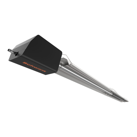
SST SERIES
superTube Heaters
LOW INTENSITY TUBE TYPE INFRARED HEATER
WITH HIGH EFFICIENCY 24VDC ECM BLOWER
Gas-fired tubular low-intensity infrared heaters
SINGLE STAGE — SUPPLEMENTARY MANUAL
A GENERAL INFORMATION MANUAL IS INCLUDED IN THE BURNER KIT
WARNING
SAFETY ALERT:
Do not store or use gasoline or other flammable vapours and liquids in the
vicinity of this or any other gas fired appliance.
IF YOU SMELL GAS
Extinguish any open flame
◼
Do not attempt to light this or any other appliance
◼
Don't touch any electrical switch, or telephone
◼
Immediately call your gas supplier from a neighbor's phone
◼
Follow any and all instruction from your gas supplier
◼
FIELD CONVERTIBILITY:
This appliance is field convertible to LP gas.
Only use a kit available from manufacturer.
Follow instructions provided in the kit and
all local and national codes.
ANSI Z83.20-2016 • CSA 2.34-2016
Improper installation, adjustment, alteration, service or
maintenance can cause property damage, injury or death.
Read the installation, operating and maintenance instruc-
tions thoroughly before installing or servicing this heater.
:
IST SERIES
Keep this manual in a secure place .
Record for future reference:
Model #:
Serial #:
SST / IST SINGLE-STAGE I&O Manual
RD: JAN 2020
RL: 2A
Advertisement


Need help?
Do you have a question about the InfraSave and is the answer not in the manual?
Questions and answers