
Related Manuals for F&F LE-01MR v2


Summary of Contents for F&F LE-01MR v2
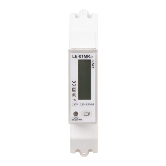
- Page 1 ul. Konstantynowska 79/81 95-200 Pabianice phone/fax 42-2152383, 2270971 e-mail: biuro@fif.com.pl 1-phase energy consumption meter LE-01MR v.2 User manual v. 1.0.0...
- Page 2 domestic and industrial automation Safety information regarding the use of the controller is indicated by the following symbols. All infor- mation and recommendations bearing these symbols must be strictly observed. Danger of electric shock. Potentially dangerous situation that could endanger operating personnel or dam- age the unit.
-
Page 3: Table Of Contents
domestic and industrial automation Table of contents Part 1. Purpose .............................. 4 Part 2. Operation ............................4 Part 3. Installation ............................5 Security measures ............................5 Mounting ..............................5 Sealing ................................ 7 Part 3. Usage ..............................8 Measurements displayed on the LCD screen..................... 8 Preview of the meter settings ........................ -
Page 4: Part 1. Purpose
Part 1. Purpose The LE-01MR v2 is an electronic, legalized (MID declaration) AC electricity meter designed for direct cur- rent measurement in 2-wire system. The meter provides 4-quadrant energy and power measurement as well as monitoring of many additional network parameters such as voltage, current, active power, reactive power, apparent power, frequency, power factor. -
Page 5: Part 3. Installation
domestic and industrial automation Part 3. Installation Security measures Installation of the device should be carried out by a qualified installers with knowledge and experience in the field of electrical installations. Please read the operating instruc- tions before installation. All installation work must be carried out with the supply voltage switched off. Ensure that the wires are carefully tightened –... - Page 6 domestic and industrial automation Functions of the meter terminals Meter current input – connection of the phase wire of the power supply line. High current cable Current output - phase wire output to supply power to the receiver. High current cable Neutral wire input.
-
Page 7: Sealing
domestic and industrial automation Sealing After connecting the meter, access to its terminals can be secured with seals connecting the meter body to the terminal covers. Security seals are not provided with the meter. LE-01MR v.2 – User manual v.1.0.0... -
Page 8: Part 3. Usage
domestic and industrial automation Part 3. Usage Direct reading of the measured values and configuration of the meter can be accessed via the controls on the front panel of the display. Reading field – LCD digital indicator displaying the value of the measured parameter. Button –... - Page 9 domestic and industrial automation reset / 8 Resettable auxiliary reactive energy meter 00000.00 (5+2) kvarh 9 Voltage 000.00 (3+2) 10 Current 000.00 (3+2) 11 Active power 00000 (5+0) 12 Reactive power 00000 (5+0) 13 Apparent power 00000 (5+0) 14 Power factor 0.00 (1+2) 15 Frequency 00.00 (2+2)
-
Page 10: Preview Of The Meter Settings
domestic and industrial automation Preview of the meter settings By pressing the button on the front panel of the meter for three seconds, a menu will be displayed that allows you to read the current meter settings. In order to switch the view to the next parameter, short press the button on the meter panel. -
Page 11: Meter Configuration
domestic and industrial automation The default value is 3. 9 The period of calculating power de- Length of time interval (in minutes) from which the value of mand power demand will be calculated. The parameter is set in the range from 1 to 30 minutes, the default value is 15 minutes. - Page 12 domestic and industrial automation • after passing the PIN verification, the first of the available configuration parameters - Id address of the meter in the RS-485 network - is displayed; • the transition between the parameters is made by short pressing the button, long pressing takes you to the edition of the selected parameter;...
- Page 13 domestic and industrial automation Resetting the maximum active The registered value of the maximum active power demand power consumption indicator appears on the display as P xxxxxx + Press and hold down the button on the front of the meter to reset the indication.
-
Page 14: Part 4. Rs-485 Communication
domestic and industrial automation Part 4. RS-485 communication The meter is equipped with a RS-485 communication interface that supports the Modbus RTU protocol. Default communication settings No. Parameter Default value: 3 Meter address in the RS-485 network 1 4 Baud rate 9600 bps None 5 Parity... - Page 15 domestic and industrial automation 4 Apparent power 0x106 INT32 5 Reactive power 0x108 INT32 6 Frequency 0x10A INT16 7 Power factor 0x10B INT16 0.001 8 Total consumed (imported) active energy 0x10E INT32 0.01 9 Total returned (exported) active energy 0x118 INT32 0.01 10 Total active energy...
-
Page 16: List Of The Configuration Registers
domestic and industrial automation Consumed (imported) reactive power de- 0x180 INT32 mand Maximum consumed (imported) reactive 0x182 INT32 power demand Returned (exported) reactive power de- 0x184 INT32 mand Maximum returned (exported) reactive 0x186 INT32 power demand List of the configuration registers To write configuration data to the LE-01MR v.2 meter you can use commands with codes: •... - Page 17 domestic and industrial automation 3 Software version 0x1004 4100 Values indicate the version of the 4 Electronics version 0x1005 4101 meter and control software. 5 CRC checksum 0x1006 4102 Time encoded in seconds. Setting range 0 - 99 seconds, a value of 0 6 Parameter display time 0x100B 4107...
- Page 18 domestic and industrial automation Energy returned (ex- port) Import + Export Import- Export Value Operation Power demand is cal- culated on the basis of successive, full time in- Calculating power de- tervals 0x1010 4112 mand Power demand calcu- lated on the basis of the moving average over a given period of time...
- Page 19 domestic and industrial automation meter configuration through the panel on the front of the meter. Value Operation Active energy meter re- 0x2000 Auxiliary energy meter 0x2002 8194 Reactive energy meter reset 0x4000 reset Active and reactive en- 0x6000 ergy meter reset To reset the selected power de- mand value, enter one of the fol- lowing values into the register...
-
Page 20: Part 8. Technical Data
domestic and industrial automation Part 8. Technical data Installation 2-wire Rated voltage 230 V AC minimum 0.02 A Current base maximum 100 A Voltage measurement range 100 – 289 V AC Accuracy of measurement (EN50470-1) Class B Rated frequency 50 Hz Insulation protection class Class II Housing... - Page 21 domestic and industrial automation Terminal 100 A current circuits (terminals 1, 3) 25 mm screw terminals neutral wire (terminals N) 1 mm screw terminals communication (terminals 23, 24, 25) 1 mm screw terminals Dimensions 1 module (18 mm) Installation on TH-35 rail Ingress protection IP40 (*) Factory setting...
-
Page 22: Part 9. History Of Changes
domestic and industrial automation Part 9. History of changes Date Version Description 2022.09.12 1.0.0 First version of the manual LE-01MR v.2 – User manual v.1.0.0... -
Page 23: Part 10. Warranty
domestic and industrial automation Part 10. WARRANTY 1. The meter is covered by a 24-month warranty. The warranty period is measured from the moment of the purchasing of the device. 2. The warranty is valid only with proof of purchase. 3. -
Page 24: Part 11. Ce Declaration
domestic and industrial automation Part 11. CE declaration F&F Filipowski sp. j. declares that the XXX device is in conformity with the essential requirements of The Low Voltage Directive (LVD) 2014/35/EU and the Electromagnetic Compatibility (EMC) Directive 2014/30/UE. The MID and CE Declaration of Conformity, along with the references to the standards in relation to which conformity is declared, can be found at www.fif.com.pl on the product page.
Need help?
Do you have a question about the LE-01MR v2 and is the answer not in the manual?
Questions and answers